Language selection

Search

Patent 2125354 Summary

Third-party information liability

Some of the information on this Web page has been provided by external sources. The Government of Canada is not responsible for the accuracy, reliability or currency of the information supplied by external sources. Users wishing to rely upon this information should consult directly with the source of the information. Content provided by external sources is not subject to official languages, privacy and accessibility requirements.

Claims and Abstract availability

Any discrepancies in the text and image of the Claims and Abstract are due to differing posting times. Text of the Claims and Abstract are posted:

  • At the time the application is open to public inspection;
  • At the time of issue of the patent (grant).
(12) Patent: (11) CA 2125354
(54) English Title: GUARD DEVICE
(54) French Title: DISPOSITIF DE PROTECTION
Status: Term Expired - Post Grant Beyond Limit
Bibliographic Data
(51) International Patent Classification (IPC):
  • E21B 17/10 (2006.01)
(72) Inventors :
  • FARRARA, ROBERT N. (United States of America)
(73) Owners :
  • CAMPBELL MANUFACTURING, LLC
(71) Applicants :
  • CAMPBELL MANUFACTURING, LLC (United States of America)
(74) Agent: MACRAE & CO.
(74) Associate agent:
(45) Issued: 1998-01-20
(22) Filed Date: 1994-06-07
(41) Open to Public Inspection: 1995-09-19
Examination requested: 1994-07-18
Availability of licence: N/A
Dedicated to the Public: N/A
(25) Language of filing: English

Patent Cooperation Treaty (PCT): No

(30) Application Priority Data:
Application No. Country/Territory Date
214,546 (United States of America) 1994-03-18

Abstracts

English Abstract


A guard device for use with a drop pipe in a well
casing includes a pair of similar guard sections each
being formed of a plastic material. Each section
includes inner and outer arcuate members interconnected
by ribs and plates. The inner arcuate member of each
section engages the drop pipe and the outer arcuate
member has tabs which engage the well casing to enter the
drop pipe. A locking member on each section interlocks
with a lock engaging member on the other section.
Vertical passages through the sections accommodate
electrical conductors, safety ropes and similar
components to thereby minimize damage to these
components.


French Abstract

Protecteur utilisé avec une colonne descendante dans le tubage d'un puits comprenant deux sections protectrices similaires fabriquées d'une matière plastique. Chaque section inclut des éléments intérieur et extérieur arrondis reliés par des nervures et des plaques. L'élément arrondi intérieur de chaque section s'engage dans la colonne descendante et l'élément arrondi extérieur comporte des griffes qui s'engage dans le tubage de puits pour entrer dans la colonne descendante. Un mécanisme de blocage sur chaque section s'enclenche dans une partie d'engagement par blocage dans l'autre section. Des passages verticaux dans les sections reçoivent les conducteurs électriques, les câbles de sécurité et les autres pièces semblables pour minimiser ainsi les dommages à ces composants.

Claims

Note: Claims are shown in the official language in which they were submitted.

WHAT IS CLAIMED IS:
1. A plastic guard device for use with a drop pipe
positioned in a well casing having a pump attached to the
lower end of the drop pipe, comprising;
a pair of similar guard sections disposed in opposing
relation and including an inner arcuate pipe engaging
member and an outer arcuate member spaced outwardly of
the inner arcuate member, a plurality of outwardly
extending tabs on the outer arcuate member and a
plurality of ribs interconnecting the inner and outer
arcuate members of each section, means on each section
defining a vertical passage through which electrical
conductors, safety ropes and similar components may pass;
each section including an elongate locking member and
a lock engaging member, each locking member on one
section engaging the lock engaging member on the other
section to releasably interlock said sections together so
that the inner arcuate members engage the drop pipe and
the tabs on the outer arcuate members engage the well
casing to thereby retain the drop pipe, electrical
conductors and safety ropes in spaced relation with
respect to the well casing.
2. The guard device as defined in claim 1 wherein
each section includes a pair of substantially flat plate
elements each interconnecting one end of the inner
arcuate member with an adjacent end of the outer arcuate
member, each plate being disposed in confronting relation
with a plate on the other section when said sections are
interconnected together in engaging relation with a drop
pipe.
-6-

3. The guard device as defined in claim 2 wherein
each locking member is integral with one of said plate
elements and projects outwardly therefrom.
4. The guard device as defined in claim 3 wherein
the other plate element of each section is slotted for
receiving a locking member therethrough, each locking
engaging member located adjacent the slotted plate
element.
5. The guard device as defined in claim 1 wherein
each locking member and each locking engaging member has
serrations thereon, the serrations on each locking member
interlocking with the serrations on the associated lock
engaging member.
6. The guard device as defined in claim 5 wherein
each lock engaging member is of generally L-shaped
configuration including an upstanding actuating handle
and a lock engaging element for engaging a locking member.
7. The guard device as defined in claim 6 wherein
each lock engaging element is relieved to define a hinge
element to facilitate movement of each lock engaging
member into and out of engaging relations with each
locking member.
-7-

Description

Note: Descriptions are shown in the official language in which they were submitted.


~ ' 212535~
.
THE GUARD DEVICE
BACKGROUND OF THE INVENTION
FIELD OF THE INVENTION
This invention relates to a guard device for use with
drop pipes in well casings.
DISCUSSION OF THE PRIOR ART
In conventional wells, the drop pipe is positioned
within a well casing and a pump is attached to the lower
end of the drop pipe. Electrical conductors, a safety
rope, cables are connected to the pipe within the well
casing and extend upwardly therethrough. If the drop
pipe, cables, ropes and electrical conductors are
suspended within the cable from the top, the drop pipe
and these other components may engage the inner wall
surface of the casing may be damaged by abrasive
interaction with the well casing.
Guard devices have been developed for preventing such
damage including U.S. Patent No. 3,933,203 which must be
strung over the end of the drop pipe section during
installation.
U.S. Patent No. 4,403,395 discloses a single piece
hinged guard device which may be releasably applied to a
drop pipe. This patent is owned by the same assignee of
the present application.
SUMMARY OF THE INVENTION
It is an object of this invention to provide a guard
device for wells comprised of a pair of similar sections

S 3 S 4
which are releasably locked together to engage and
position a drop pipe in spaced relation within a well
casing to provide passages for electrical conductors,
safety ropes or cables attached to a pump located at the
bottom of the drop pipe.
The guard device includes a pair of substantially
identical plastic sections each including an inner
arcuate pipe engaging member and an outer arcuate member.
The outer arcuate member for each section has a plurality
of tabs integral therewith which extend outwardly there-
from to engage the inner surface of the well casing.
Each section includes a locking member and a lock engag-
ing member. The locking member on one section engages
the lock engaging member on the other section to
releasably lock the sections together in engaging rela-
tion with the drop pipe to maintain the drop pipe in
spaced relation with respect to the casing. Each section
also has at least one vertically disposed passage therein
between the inner and outer arcuate members for accommo-
dating electrical conductors, safety ropes and similar
components.
BRIEF DESCRIPTION OF THE FIGURES OF THE DRAWING
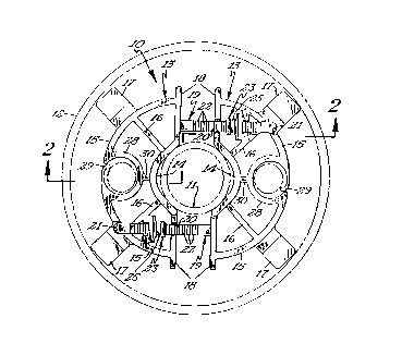
Fig. 1 is a top plan view of the guard device in
engaging relation with a drop pipe and with a well
casing;
Fig. 2 is a side elevational view of the guard device
secured to a drop pipe and engaging the well casing.
Fig 3 is a cross-sectional view illustrating the
locking member on one section and a lock engaging member
on the other.
DESCRIPTION OF THE PREFERRED EMBODIMENT
Referring now to the drawings, it will be seen that

212535~
.
one embodiment of the novel guard device, designated
generally by the reference numeral 10, is thereshown.
The guard device 10 is formed of a molded plastic
material and when used engages a conventional drop pipe
11 positioned within a well casing 12. It is pointed out
that the drop pipe 11 extends vertically downwardly
within the casing 12 and is connected to a pump at its
lower end in the conventional manner. The well casing 12
projects upwardly to the surface while the drop pipe is
connected to a lateral delivery pipe in a well known
manner. Although all of these well features are not
disclosed in the drawings, the features are well
illustrated in U.S. Patent No. 4,483,395 and are
incorporated by reference herein.
The guard device 10 is comprised of a pair of
substantially identical guard device sections 13 each
including an inner arcuate pipe engaging member 14 and an
outer arcuate member 15 interconnected to the inner
arcuate member by suitable ribs 16.
The outer arcuate member 15 for each section 13 has a
pair of outwardly extending tabs 17 integrally formed
therewith and projecting outwardly therefrom. It will be
seen that each tab 17 engages the inner surface of the
well casing when the guard device is applied to a drop
bucket. It will also be seen that each end of the inner
arcuate pipe engaging member 14 is connected to the
adjacent end of the outer arcuate member by one of a pair
of interconnecting plates 18, as best seen in Fig. 2.
The plates 18 rib 16 and outer arcuate member 15 all have
substantially identical vertical or axial dimensions, and
these dimensions are substantially smaller than the
vertical or axial dimension of the inner arcuate pipe
engaging member 14.
One of the interconnecting plates 18 for each section
13 has an elongate substantially straight locking member

2125354
19 integrally formed therewith and projecting outwardly
therefrom. The other interlocking plate 18 of each
section 13 has a notch or slot 20 therein of a size to
accommodate the locking member 19 therethrough. It will
also be noted that the outer arcuate member 15 of each
section has a slot or notch 21 therein and that the
adjacent rib 16 is recessed to accommodate the locking
member 19 from the adjacent section 13. The upper
surface of each locking member has a plurality of
upwardly facing serrations or teeth 22 formed thereon
intermediate the ends thereof.
Each section 13 is also provided with a lock engaging
member 23 which is integral with the recessed rib and
with the outer arcuate member 15. Referring now to Fig. 3,
it will be seen that each lock engaging member 23
includes an elongate upwardly projecting handle or thumb
tab 24 which is connected at its lower end to a lock
engaging lower portion 25 disposed at right angles to
the handle 24. It will be seen that the lock engaging
lower portion 25 has a plurality of downwardly extending
teeth 26 formed along a portion of its lower surface for
engagement with the teeth or serations 22 on one of the
locking members 19. The lock engaging lower portion 25
is also relieved or recessed intermediate its length to
form a hinge 27 to permit vertical flexing movement of
the lock engaging member.
Each section 13 also has a cylindrical element 28
integrally formed with the outer arcuate member 15
intermediate the ends of the latter. Each cylindrical
element 28 has a vertically extending mold-in opening
29 therein and is interconnected with the adjacent inner
arcuate member 14 by a small rib 30. The cylindrical
element 28 also has a vertical dimension corresponding to
the vertical dimension of the outer arcuate member. The
opening 29 in the cylindrical element 28 permits an

2125354
electrical conductor or safety rope to be moved through
the opening and positioned within the cylindrical element.
The enlarged end portion 31 of the cylindrical member
adjacent the opening 29 resists accidental dislodgment
conductor through the opening 29.
In use, the sections 13 will be positioned in opposed
relation with each other and will be urged towards each
other so that the locking members 19 will pass through
the slots 20, 21 on the opposite section the lock
engaging members 23 will be flexed to the open position
to allow movement of the locking members 19 past the lock
engaging members 23. The sections will continue to be
urged towards each other until the inner arcuate pipe
engaging member engages the pipe and with the
interconnecting plates on the respective sections being
disposed in closely spaced confronting relation. The
lock engaging members 23 will be released to lock the
sections 13 together and to the drop pipe 11. When guard
devices are applied to a drop pipe along the length of
the latter, the electrical conductors, ropes and other
elements connected to the pump will be spaced inwardly of
the casing 12 since the tabs 17 will engage the inner
surface of the casing. The pipe 11 will be substantially
centered and will be held against abrasive engagement
with the well casing.
The guard device 10 may be readily applied to drop
pipes 11 of conventional size without requiring any tools
and will retain the drop pipe in centered relation within
the casing while retaining the saftey rope and electrical
conductors within the confines of the guard device.
It will therefore be seen that I have provided a
novel guard device for use with drop pipes located within
well casings which guard device functions to
substantially center the drop pipe while preventing
damage to the drop pipe safety ropes, electrical
conductors and other components by abrasive action with
the well casing.
--5--

Representative Drawing
A single figure which represents the drawing illustrating the invention.
Administrative Status

2024-08-01:As part of the Next Generation Patents (NGP) transition, the Canadian Patents Database (CPD) now contains a more detailed Event History, which replicates the Event Log of our new back-office solution.

Please note that "Inactive:" events refers to events no longer in use in our new back-office solution.

For a clearer understanding of the status of the application/patent presented on this page, the site Disclaimer , as well as the definitions for Patent , Event History , Maintenance Fee  and Payment History  should be consulted.

Event History

Description Date
Inactive: Expired (new Act pat) 2014-06-07
Letter Sent 2009-06-02
Small Entity Declaration Determined Compliant 2008-04-23
Inactive: Office letter 2003-07-14
Inactive: Reversal of will be deemed expired status 2003-07-14
Letter Sent 2003-06-09
Grant by Issuance 1998-01-20
Inactive: Application prosecuted on TS as of Log entry date 1997-11-14
Inactive: Status info is complete as of Log entry date 1997-11-14
Pre-grant 1997-10-03
Notice of Allowance is Issued 1997-04-22
Application Published (Open to Public Inspection) 1995-09-19
All Requirements for Examination Determined Compliant 1994-07-18
Request for Examination Requirements Determined Compliant 1994-07-18

Abandonment History

There is no abandonment history.

Fee History

Fee Type Anniversary Year Due Date Paid Date
Final fee - small 1997-10-03
MF (patent, 4th anniv.) - small 1998-06-08 1998-05-27
MF (patent, 5th anniv.) - small 1999-06-07 1999-06-03
MF (patent, 6th anniv.) - small 2000-06-07 2000-05-24
MF (patent, 7th anniv.) - small 2001-06-07 2001-04-23
MF (patent, 8th anniv.) - small 2002-06-07 2002-05-13
MF (patent, 9th anniv.) - small 2003-06-09 2003-05-28
MF (patent, 10th anniv.) - small 2004-06-07 2004-04-23
MF (patent, 11th anniv.) - small 2005-06-07 2005-04-11
MF (patent, 12th anniv.) - small 2006-06-07 2006-04-24
MF (patent, 13th anniv.) - small 2007-06-07 2007-05-02
MF (patent, 14th anniv.) - small 2008-06-09 2008-04-23
Registration of a document 2008-09-15
MF (patent, 15th anniv.) - standard 2009-06-08 2009-05-27
MF (patent, 16th anniv.) - small 2010-06-07 2010-05-20
MF (patent, 17th anniv.) - small 2011-06-07 2011-05-10
MF (patent, 18th anniv.) - small 2012-06-07 2012-04-23
MF (patent, 19th anniv.) - small 2013-06-07 2013-05-10
Owners on Record

Note: Records showing the ownership history in alphabetical order.

Current Owners on Record
CAMPBELL MANUFACTURING, LLC
Past Owners on Record
ROBERT N. FARRARA
Past Owners that do not appear in the "Owners on Record" listing will appear in other documentation within the application.
Documents

To view selected files, please enter reCAPTCHA code :


To view images, click a link in the Document Description column. To download the documents, select one or more checkboxes in the first column and then click the "Download Selected in PDF format (Zip Archive)" or the "Download Selected as Single PDF" button.

List of published and non-published patent-specific documents on the CPD .

If you have any difficulty accessing content, you can call the Client Service Centre at 1-866-997-1936 or send them an e-mail at CIPO Client Service Centre.


Document
Description 
Date
(yyyy-mm-dd) 
Number of pages   Size of Image (KB) 
Abstract 1995-09-19 1 19
Cover Page 1995-11-01 1 14
Description 1995-09-19 5 214
Claims 1995-09-19 2 67
Drawings 1995-09-19 1 43
Description 1997-04-22 5 211
Cover Page 1998-01-28 1 54
Representative drawing 1998-01-28 1 16
Courtesy - Certificate of registration (related document(s)) 2009-06-02 1 102
Correspondence 2003-07-14 1 14
Correspondence 2008-04-23 1 43
Fees 2009-05-27 1 28
Maintenance fee payment 1997-04-25 1 52
Maintenance fee payment 1996-05-28 1 55
Prosecution correspondence 1994-06-07 4 189
Prosecution correspondence 1995-04-24 5 360
Prosecution correspondence 1994-07-18 1 24
Prosecution correspondence 1997-02-07 1 34
Examiner Requisition 1996-12-06 1 50
Prosecution correspondence 1995-04-24 1 32
Courtesy - Office Letter 1995-01-16 1 64
Maintenance fee correspondence 1997-10-03 1 31