Note: Descriptions are shown in the official language in which they were submitted.
2 1 ~
IMPROVED D~IVE SY5TEM FOR MODULAR LINK CONvEYO~ ~ELTS
TECHNICAL FIELD:
~his invention relates to modular conveyor belts o variable
widths and lengths ormed from pivoted links, preferably plastic,
and more particularly it relates to modular driving belt loops in
surface to surface driving relationship to the conveyor belts as
locomotion means for the modular conveyor belts.
BACKGROUND ART:
Modular link conveyor belts are conventionally formed as
belt loops driven by power driven ~procket wheels located at one
or two ends of the loop. For heavily loaded belts the power drive
~ystem dependent upon a few sprocXet teeth about the sprocket ~ -
wheel in driving contact with the belt modules passing over the
wheel presents a series of problems. With strong sprocket teeth -
and powerful drive forces plastic belts wear and have short life.
Also the drive forces are not usually at the most heavily loaded
portions of the belt and must transmit the drive for~es through a -~
chain of link to pivot rod couplings, thus creating tension in
the belt requiring heavy duty modules. Furthermore the loading at
the pivot joint accelerates wear. This type of drive system is
particularly unacceptable in long belts or belts disposed in
curved paths.
Conveyor belt and chain drive systems that employ a loop
belt in place of a drive sprocket to drive a coDveyor belt system
,-
,
212J~
}l~ve been proposed in the prior art Lor distributing drlving
forces <~ver a longer conveyor belt portion and thus reducing
tension in the conveyor belt. U. S. Patents 1,939,315, Paulson,
Dec. 12, 1933; 1,960,719, Stibbs, May 29, 1934; 2,405,530,
Sullivan, Aug. 6, 1946; 2,86~,356, Haaff, Jan. 13, 1959; and
4,058,204, Arich, Nov. 1~, 1977 represent these prior art drive
systems. These systems, in general, are not compatible with
modular link belts having pivotable plastic links which are
subjected to significant wear and excessive belt tension in the
presence of heavy ~r variable loading.
Also in these prior art drive systems there are many other
deficiencies and limitations, particularly for universal usage
with a large variety of conveyor systems employing belts of
various widths, lengths and travel path configurations where
drive belts require a variety of configurations. One serious
deficiency in custom ~ade complex drive belts adapted to various
conveyor belt conditions is the necessity to produce and stoc~
special drive belt links in relatively small quantities thereby
sigr.ificantly increasing the cost of the driving belt systems.
Conveyor belts that travel about curved paths in particular
present driving problems not solved by the prior art.
A significant problem not addressed by the prior art is the
compatibility of the drive belt with the conveyor belt under
actual working conditions. For example if there are different
dimensional changgs in the modules of the respective belts in
response to temperature or manufacturing tolerances, the two
2 1 ~
~lts will incur incompatibilitY re~ulting in interference, power
loss and increased wear.
It is accordingly an ob~ect of this invention to provide
improved conveyor belt drive systems of the type that engage a~
~odular link conveyor belt in a driving relationship by an
endless loop modular driving belt extending along a significant
portion of the modular link belt length, thereby to relieve
tension, reduce wear and relate driving forces to load bearing
portions of the conveyor belt.
A further object of the invention i~ to provide conveyor
belt drive systems of significantly universal adaptability to
~elts of various lengths, widths, loadings and path
configurations.
Another object of the invention is to provide plastic
~odular link driving belt ~ystems for engaging a pla~tic modular
link conveyor belt with co~patible performance under working
conditions.
DISCLOSURE OF THE INVENTION~
In a preferred embodiment of this invention therefore a
modular plastic link conveyor belt is driven by a ~odular plastic
20 link driving belt loop with identical links employed in each belt ~-~
to compatibly operate in the presence of changing loads and .
temperatures.
: The drive system of this invention is universally adaptable
to various belt configurations without the requirement for -- :
212S'i~l~
s~ocking special modular links. Thus, one or more narraw drive
belt l~ops may drive wlder conveyor belt~ and ~everal drive belt
loop units may be inserted at key load bearing positio~s in the
conveyor belt to bear the loading with less belt tension and
wear, making long belt~ having conveying surface uninterrupted by
transfer gaps feasible. Also the drive belt. loops afford special
advantages in curved conveyor belt path embodiments and in
uninterrupted single-level racetrack configurations.
Other objects, features and advantages of the invention are
set forth throughout the following description, claims and
drawings.
THE DRAWINGS:
Like reference characters are used for sLmilar features
throughout the various views to facilitate comparison. In these
drawings:
Figure 1 is a fragmental side view, partly in section, of a
conveyor drive system embodiment of the invention, - :
Figure 2 is a fragmental side view, partly in section, of a
longer section of the conveyor drive system of Figure 1,
Figure 3 is a plan-view of a horizontal segment of the drive
belt loop shown in Figure 1 with the conveyor belt removed,
Figures 4A and 4B are partial sectional end view sketches of
the top portion of conveyor drive system embodiments afforded by
this invention along cut-line 1-1 of Figure 2, and
2 1 2 ^~
Figure 5 is a plan view sketch c,f an embodiment of the
conveyor belt drive sy~tem for a conveyor having a curved path.
THE PREFERRED EMBODIMENT:
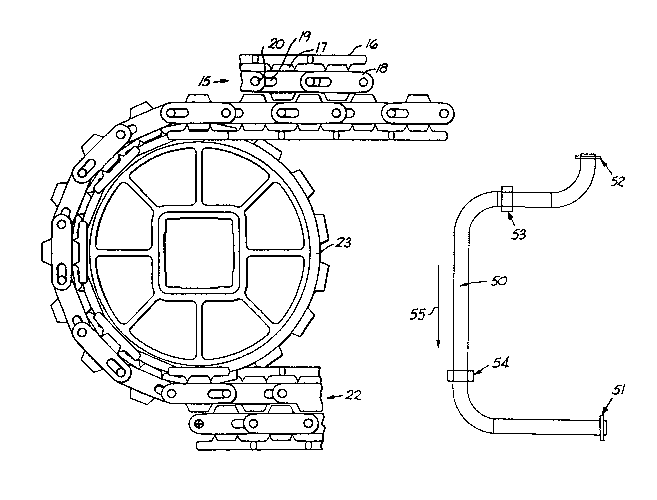
As seen from Figure 1, the fragmental portion of the
conveyor belt 15 carries platform members, or raised ribs 16,
extending above the drive bars 17 that protrude on either side of
the modular links 18. Thèse rai~ed ribs or members 16 convey a
load along the path of the conveyor belt 15. Elongated ~lots 19
on at least one end for journalling pivot rods 20 and the modular
links 18 are of the nature set forth in Lapeyre patent 4,934,517,
June 19, 1990, thereby affording flexibility for the conveyor
belt lS to travel around curved paths, such as shown in Figure 5.
As also shown in ~igure 2, the outermost conveyor-loop 15, only ~ -
partially shown, is driven by an innermost modular plastic link
belt loop 22, which in turn iG driven by one or more sprocket
wheels 23. The drive belt 22 thus serves as an intermediate drive - -~
that distributes the drive forces over more ~odular links than ~
feasible with sprockets, and therefore reduces tensions and wear -. ~.
in the conveyor belt loop 15. To operate long or heavily loaded -
belts without exceeding the belt's rating, the drive belt 22 can
20 engage the driven belt 15 on the return path as well. It is seen .
that the drive bars 17 in the space between the pivot rods 20 in
the respective belts 15, 22 serve as alternating gear teeth
coupled in a drive-driven relationship. In order to achieve this,
S; ~
~ ` 2 1 ~
tlle driving belt 22 i8 turned "inside-out" with the platform
members 16 disposed innermost.
In such a configuration, the modular links in both the
driven conveyor belt and the driving belt are identical. Such a
relationship is particularly advantageous in that it assures
' optimal performance over a large range of operating conditions
and over an extended life period. ~hus, for example, temperature
variations and manufacturing tolerances are similar in ~oth the
driven and driving belt modules. Furthermore specialty drive
links do not have to be manufactured at higher cost and with
special characteristics not present in the mass produced conveyor
belt links.
It is seen therefore that drive belt loops of various
lengths and widths can be easily fashioned to meet the design
crite~ia for different belt load and operating conditions. For
example sprocket wheel 23 at either end of the loop includes one
or more power driven sprockets and one or more idler sprockets
depending upon the power and loading conditions of any
particular belt system. Also the length and width of the driving
belt may be configured to best suit the conveyor system under
consideration. If there is a special loading condition imposed by
a conveyed product or the length of the conveyance path, the
drive belt loop can be made longer, or wider, etc. As seen in
Figures 4A and 4B, which show conveyor belts 15 engaged by drive
belts 22', 22" driven by sprockets 23 on a drive shaft 24, the
conveyor belts 15 can carry lighter loads 25, or heavier loads
2 1 ~
2.. ~ccordingly the d~ive belts may be narrow or wide, and if
more than one acro~s the conveyor belt width they may be placed
at strategic loading positions, such as near the edges of the
driven belt.
~ he top view of the wider drive belt embodiment 22 is ~hown
in Figure 3. The bar drive tooth structure 17 is shown as a
common bar extending across the width of the driving belt. In
this embodiment the modular links 30 are lined up in parallel and
intçgrally affixed to the bars 17. These modules may extend
across the width of the belt or partially across to accommodate
~bricklayering~ patterns. Alternatively, belts may be formed of
side by side elemental links, but they are more costly in
manufacture and assembly. Sprocket teeth fit in the gaps 32
between the links 30 and drive against the rearward drive ~urface
33 of the drive bar 17. The forward drive ~urface 34 of the bar
17 on the opposite side of the belt module 22 drivingly engages
the drive bar of the driven belt for the drive-driven
relationship between the innermost driving loop and the outermost
driven conveyor belt.
Thus this invention affords two adjacent belts, each formed
of plastic link modules into endless belt loop assemblies,
wherein an innermost belt has drive teeth on its outer surface
that intermesh with mating drive teeth on the lower inner surface
of the conveyor belt in a driving-driven relationship. The inner
belt is powered by a sprocket wheel assembly. The modules form
oblong links with parallel upper and lower surfaces disposable
21~S'j~
along the lengtll of the belt and intercon~ected with pivot rods
passing through apertures near each link end. Drive tooth or bar
appendages of generally trapezoidal ~hape extend from the links
on both sides of the belts, and on the conveyor loading side
raised ribs extend beyond the teeth to form a load support
platform. The inner belt is assembled "inside-out" to put the
load support ribs innermost thereby producing a set of
intermeshed gear teeth formed by the drive bars disposed between
the pivot rods of the respective belts.
The drive system is particularly adaptable to curved
conveyor paths, such as illustrated in Figure 5 with the conveyor
belt SO disposed between the drive sprocket 51 and the idler
sprocket 52 in an endless loop driven in the direction of arrow
5S. If the driving forces were all delivered by drive sprocket
51, great tension loads would be introduced along the belt, and
optimum power would not be applied in the loaded portions of the
belt. Thus, if the inner drive belts of this invention are
positioned at 53 and 54, each branch of the belt system has a
powered sprocket type drive pulling the belt around the
respective bends. Other configurations requiring multiple drive
positions, for example at heavier loaded work stations along the
conveyor belt length, will afford advantages with the belts of
this invention. ~
' ~:
. ~
, ~' . ~ ,`.';.`, '
.
It. is accordingly seen that this invention provides
significant improvements in the state of the art, and those
features of novelty setting forth the nature and spirit of the
invention are defined with particularity in the following
claims.