Language selection

Search

Patent 2126454 Summary

Third-party information liability

Some of the information on this Web page has been provided by external sources. The Government of Canada is not responsible for the accuracy, reliability or currency of the information supplied by external sources. Users wishing to rely upon this information should consult directly with the source of the information. Content provided by external sources is not subject to official languages, privacy and accessibility requirements.

Claims and Abstract availability

Any discrepancies in the text and image of the Claims and Abstract are due to differing posting times. Text of the Claims and Abstract are posted:

  • At the time the application is open to public inspection;
  • At the time of issue of the patent (grant).
(12) Patent Application: (11) CA 2126454
(54) English Title: LASER TABLET TREATMENT SYSTEM WITH DUAL ACCESS TO TABLET
(54) French Title: SYSTEME DE TRAITEMENT DE COMPRIMES A LASER AYANT UN DOUBLE ACCES AUX COMPRIMES
Status: Deemed Abandoned and Beyond the Period of Reinstatement - Pending Response to Notice of Disregarded Communication
Bibliographic Data
(51) International Patent Classification (IPC):
  • B23K 26/08 (2014.01)
(72) Inventors :
  • RIDDLE, THOMAS ARMEN (United States of America)
  • GEERKE, JOHAN HENDRICK (United States of America)
  • MINTON, KEITH PERRY (United States of America)
(73) Owners :
  • ALZA CORPORATION
(71) Applicants :
  • ALZA CORPORATION (United States of America)
(74) Agent: SMART & BIGGAR LP
(74) Associate agent:
(45) Issued:
(86) PCT Filing Date: 1993-01-14
(87) Open to Public Inspection: 1993-07-22
Availability of licence: N/A
Dedicated to the Public: N/A
(25) Language of filing: English

Patent Cooperation Treaty (PCT): Yes
(86) PCT Filing Number: PCT/US1993/000345
(87) International Publication Number: US1993000345
(85) National Entry: 1994-06-21

(30) Application Priority Data:
Application No. Country/Territory Date
07/820,704 (United States of America) 1992-01-14

Abstracts

English Abstract

2126454 9313909 PCTABS00024
Tablet treating system (10) treats a series of pharmaceutical
tablets (50T) with pulses of laser energy (24P) within at least one
predetermined treatment site (50S) on each tablet. A tablet
conveyer (12) continuously moves individual tablets along a tablet
path (10P). A laser (14) provides the pulses of laser energy along a
stationary laser path which crosses the tablet path defining a
stationary intersection zone (14Z) common to both paths. The
tablet path has periodic treatment windows (20W) during which the
treatment sites (50S) on the moving tablets pass through the
stationary intersection zone. The operation of the laser has periodic
laser ready windows (24W) during which the laser may be fired. A
controller (16) is responsive to the movement of the tablet conveyer
and to the operation of the laser for activating the laser and
treating the tablets. The controller activates the laser when a
tablet is passing through the intersection zone and the tablet
treatment window coincides with the laser ready window. The
controller does not activate the laser and rejects the tablet when the
tablet treatment window does not coincide with the laser ready
window. An abort mechanism (18) proximate the collection end (10C) of
the tablet path is responsive to the controller for separating
the treated tablets from the rejected tablets.


Claims

Note: Claims are shown in the official language in which they were submitted.


14
CLAIMS:
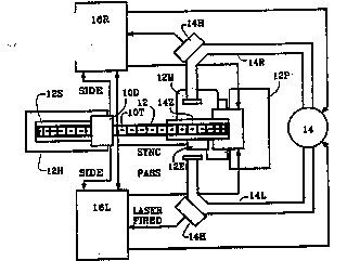
1. A tablet treating system (10) for treating
pharmaceutical tablets (10T, 50T) with pulses of laser energy
within at least one predetermined treatment site (50S) on each
tablet, comprising conveying means (12) for moving a series of
individual tablets (10T,50T) along a tablet path (10P) having a
supply end (10S) for receiving untreated tablets (10T,50T) and
having a collection end (10C);
abort means (18) proximate the tablet path (10P) and
responsive to a controller means (16R,16L) for separating the
treated tablets (10T,50T) from the untreated tablets (10T,50T),
the tablet treating system (10) being characterized by:
laser means (14) for periodically providing the pulses of
laser energy along a stationary laser path (14R,14L) which crosses
the tablet path (10P) defining a stationary intersection zone
(14Z) common to both paths (14R,10P and/or 14L,10P), wherein
during the operation of the laser means (14) the laser means (14)
having laser ready windows (24W) during which the laser means (14)
may be fired;
whereby the tablets (10T, 50T) moving along the tablet path
(10P) cause the treatment sites (50S) to periodically pass through
the stationary intersection zone (14Z) during tablet treatment
windows (20W); and
the controller means (16R, 16L) being responsive to the
movement of the tablet conveyer means (12) and to the operation of
the laser means (14) for activating the laser means (14) and
treating a tablet 10T,50T) when the tablet (10T,50T) is passing
through the intersection zone (14Z) and the tablet treatment
window (20W) occurs during a sufficient portion of the laser ready
window (24W) to apply a pulse of laser energy during that portion
of time, and for not activating the laser means (14) and rejecting
the tablet (10T,

50T) when the tablet treatment window (20W) does not occur during
a sufficient portion of the laser ready window (24W) to apply a
pulse of laser energy during that portion of time.
2. The tablet treating system of claim 1, wherein the
laser means (143 provides the pulses of laser energy along one
laser path (14R,14L) striking one side of the tablet (10T,50T) for
treating that one side.
3. The tablet treating system of claim 1, wherein the
tablet (10T,50T) has a first side and a second side, and the laser
means (14) provides pulses of laser energy along either of two
laser paths (14R,14L), including a first laser path (14R) striking
the first side of the tablet (10T,50T) for treating the first side
as a treatment site (50S) on the first side passes through the
intersection zone (14Z), and a second laser path (14L) striking
the second side of the tablet (10T,50T) for treating the second
side as a treatment site (505) on the second side passes through
the intersection zone (14Z).
4. The tablet treating system of claim 3, wherein the
laser means (14) treats both the first side and the second side of
the tablet (10T,50T) as the treatment sites (50S) thereon pass
through the intersection zone (14Z).
5. The tablet treating system of claim 3, wherein the
laser means (14) treats only one side of the first and second
sides of the tablet (10T,50T) as the treatment sites (50S) on the
only one side pass through the Intersection zone (14Z).
6. The tablet treating system of claim 1, further
comprising:
tablet supply means (12H) proximate the supply end (10S) of
the tablet path (10P) for containing a reserve of tablets (10T,

15a
..:.; ''. ; ,:
50T) which are loaded onto the conveyer means (12) for treatment
with the pulses of laser energy;

16
pass collection means (12P) positioned proximate the abort means
(18,38) at the collection end (10C) of the tablet path (10P) for
collecting the treated tablets (10T,50T); and
reject collection means (12R) positioned proximate the abort
means (18,38) at the collection end (10C) of the tablet path (10P)
for collecting the rejected tablets (10t,50T).
7. The tablet treating system of claim 6, wherein the
tablet moving means (12) further comprises:
endless carrier means (12) extending from the tablet supply
means (12H) through the intersection zone (14Z) to the collection
end (10C) and back to the tablet supply means (12H) for moving the
tablets (10T,50T) along the tablet path (10P) through the
intersection zone (14Z) for treatment;
a supply wheel (12S) mounted proximate the tablet supply
means (12H) for engaging the supply end (10S) of the endless
carrier means (12); and
a collection wheel (12C) mounted proximate the collection
end (10C) of the tablet path (10P) for engaging the collection end
(10C) of the endless carrier means (12).
8. The tablet treating system of claim 7, wherein the
supply wheel (12S) is positioned in the tablet supply means (12H)
for permitting the tablets (10T,50T) to load onto the endless
carrier means (12), and the collection wheel (12C) is positioned
higher than the supply wheel (12S) to create a positive slope in
the tablet path (10P) between the supply wheel (12S) and the
collection wheel (12C) which raises the tablets (10T,50T) out of
the tablet supply means (12H).
9. The tablet treating system of claim 7, wherein the
conveyer means (12) further comprises:

WO 93/13909 PCT/US93/00345
17
drive means (12M) for driving the endless carrier means (12)
around the supply wheel (12S) and the collection wheel (12C) for
moving the tablets (10T,50T) along the tablet path (10P).
10. The tablet treating system of claim 9, wherein the
collection wheel (12C) is a drive wheel and is turned by the drive
means (12M) to move the endless carrier means (12), and the supply
wheel (12S) is an idler wheel.
11. The tablet treating system of claim 9, wherein the
conveyer means (12) further comprises:
a rotary encoder means (12E) responsive to the drive means
(12M) for providing periodic sync counts (22H) to the controller
means (16) for synchronizing the position of the moving tablets
(10T,50T) on the carrier means (12) relative to the stationary
intersection zone (14Z).
12. The tablet treating system of claim 11, wherein the
endless carrier means (12) is a carrier chain formed by carrier
links (52L).
13. The tablet treating system of claim 12, wherein the
encoder means (12E) provides a sync home count (22H) defining a
sync period (22J) as each carrier link (52L) in the endless
carrier chain (12) approaches the intersection zone (14Z).
14. The tablet treating system of claim 13, wherein the
each carrier link (52L) in the endless carrier chain (12) carries
one tablet (10T,50T) to be treated.
15. The tablet treating system of claim 13, wherein the
encoder means (12F) provides a predetermined number of sync
increment counts (22I) between sequential sync home counts (22H).
16. The tablet treating system of claim 15, wherein the
controller means (16) further comprises:

WO 93/13909 PCT/US93/00345
18
lead counter means (46L) responsive to the sync increment
counts (22I) from the encoder (12E) for defining the distance
along the tablet path (10P) between the sync home count (22H) and
the start of the treatment window (20W) corresponding to the
leading edge of the treatment site (50S) on the moving tablet
(10T,50T).
17. The tablet treating system of claim 16, wherein the
controller means (16) further comprises:
window counter means (46W) responsive to the lead counter
means (46L) and to the sync increment counts (22I) for defining
the distance along the tablet path (10P) between the start of the
treatment window (20W) and the end of the treatment window (20W)
corresponding to the trailing edge of the treatment site (50S) on
the moving tablet (10T,50T).
18. The tablet treating system of claim 6, wherein the
abort means (18,38) further comprises:
a reject mode of operation for directing the rejected
tablets (10T,50T) into the reject collection means (12R):
a pass mode of operation for directing the treated tablets
(10T,50T) into the pass collection means (12P); and
actuator means (38A) for changing the mode of the operation
of the abort means (18,38).
19. The tablet treating system of claim 18, wherein the
actuator means (38A) has a default non-actuated condition which
establishes the reject mode of operation, and an actuated
condition which establishes the pass mode of operation.
20. The tablet treating system of claim 19, wherein the
actuator means (38A) is a spring return solenoid (38S) which
maintains the abort means (18,38) in the reject mode when

WO 93/13909 PCT/US93/00345
19
nonactuated, and which advances the abort means (18, 38) to the
pass mode when actuated.
21. The tablet treating system of claim 18, wherein the
abort means (18,38) further comprises:
collection channel means (38C) for receiving the tablets
(10T,50T) from the collection end (10C) of the conveyer means
(12); and
diverter means (38D) responsive to the actuator means (38A)
for directing the collected tablets (10T,50T) into the reject
collection means (12R) and the pass collection means (12P).
22. The tablet treating system of claim 21, wherein the
collection channel means (38C) further comprises:
a generally downward directed reject chute (38C) in
communication with the reject collection means (12R);
a generally downward directed pass chute (38P) in
communication with the pass collection means (12P);
the reject chute (38C) having an entrance leading to the
pass chute (38P); and
the diverter means (38D) blocks the entrance to the pass
chute (38P) during the reject mode of operation, and opens the
entrance to the pass chute (38P) and blocks the reject chute (38C)
during the pass mode of operation.
23. The tablet treating system of claim 18, wherein during
the reject mode of operation, the abort means (18,38) rejects the
tablet (10T,50T) currently at the intersection zone (14Z), and
rejects "A" tablets (10T,50T) ahead of the rejected tablet
(10T,50T) currently at the intersection zone (14Z), and rejects

20
"B" tablets (10T,50T) behind the rejected tablet (10T,50T)
currently at the intersection zone (14Z).
24. The tablet treating system of claim 23, wherein "A"
equals "B".
25. The tablet treating system of claim 18, wherein the
abort means (18,38) has an initial start mode of operation in
which the first "S" tablets (10T,50T) are rejected.
26. The tablet treating system of claim 1, wherein the
conveying means (12) continuously moves the tablets (10T, 50T)
along the tablet path.
27. The system of claim 26, wherein the abort means is
proximate a collection end of the tablet path.
28. A controller (16R, 16L) for a tablet treating system
(10) for treating pharmaceutical tablets (10T, 50T) with pulses of
laser energy within at least one predetermined treatment site
(50S) on each tablet, the tablet treating system (10) including
means (12) for conveying a series of individual tablets (10T, 50T)
along a tablet path (10P), laser means (14) for providing the
pulses of laser energy along a stationary laser path (14R, 14L)
which crosses the tablet path (10P) defining a stationary
intersection zone (14Z) common to both paths (14R, 10P and/or 14L,
10P), periodic treatment windows (20W) during which the treatment
sites (50S) on the moving tablets (10T,50T) pass through the
stationary intersection zone (14Z), and laser ready windows (24W)
in the operation of the laser means (14) during which the laser
means (14) may be fired, the controller (16R, 16L) being
characterized by being responsive to a parameter selected from the
group consisting of (i) the movement of the tablets (10T, 50T),
(ii) the position of the tablets (10T, 50T), (iii) the position of
the tablet conveying means (12), and (iv) the movement of the
tablet conveying means (12), the controller (16R, 16L) also being
responsive to the operation of the laser means (14) for activating

21
the laser means (14) and treating a tablet (10T, 50T) when the
tablet is passing through the intersection zone (14Z) and the
tablet treatment window (20W) coincides with a sufficient portion
of the laser ready window (24W) to accomodate the laser pulse.
29. The controller of claim 28, wherein the controller
(16R, 16L) does not activate the laser means (14) and rejects the
tablet (10T, 50T) when the treatment window (20W) does not
coincide with a sufficient portion of the laser ready window (24W)
to accomodate the laser pulse.
30. The controller of claim 29, wherein the tablet
treating system (10) further includes abort means (18) proximate
the tablet path (10P), the abort means (18) being responsive to
the controller (16R, 16L) for separating the treated tablets from
the rejected tablets.
31. The controller of claim 30, the abort means (18)
further including a reject mode of operation for directing
rejected tablets (10T, 50T) into a reject collection means (12R),
a pass mode of operation for directing treated tablets (10T, 50T)
into a pass collection means (12P),
wherein during the reject mode of operation, the abort means
(18) rejects the tablet currently at the intersection zone (14Z),
and rejects "A" tablets ahead of the rejected tablet currently at
the intersection zone, and rejects "B" tablets behind the rejected
tablet currently at the intersection zone.
32. The controller of claim 31, wherein "A" equals "B".
33. The controller of claim 30, the abort means (18)
further including a reject mode of operation for directing
rejected tablets into a reject collection means (12R), a pass mode
of operation for directing treated tablets into a pass collection
means (12P), wherein the abort means (18) has an initial start
mode of operation in which the first "S" tablets (10T, 50T) are
rejected.

22
34. The controller of claim 287 wherein the conveying
means (12) further includes drive means (12M) for driving an
endless carrier chain (12) formed by carrier links (52L), a rotary
encoder means (12E) responsive to the drive means (12M) for
providing (i) periodic sync counts (22H) to the controller means
for synchronizing the position of the moving tablets (10T, 50T) on
the carrier means (12) relative to the stationary intersection
zone (14Z), (ii) a sync home count (22H) defining a sync period
(22J) as each carrier link (52L) in the endless carrier chain (12)
approaches the intersection zone (14Z), and (iii) a predetermined
number of sync increment counts (22I) between sequential sync home
counts (22H), and wherein the controller (16R, 16L) further
comprises;
lead counter means responsive to the sync increment counts
(22I) from the encoder (12E) for defining the distance along the
tablet path (10P) between the sync home count (22H) and the start
of the treatment window (20W) corresponding to the leading edge of
the treatment site (505) on the moving tablet (10T, 50T).
35. The controller of claim 34, further comprising window
counter means responsive to the lead counter means and to the sync
increment counts (22I) for defining the distance along the tablet
path (10P) between the start of the treatment window (20W) and the
end of the treatment window (20W) corresponding to the trailing
edge of the treatment site (50S) on the moving tablet (10T, 50T).
36. A method for treating pharmaceutical tablets (10T<
50T) with pulses of laser energy within at least one predetermined
treatment site (50S) on each tablet, comprising conveying a series
of individual tablets (10T, 50T) along a tablet path (10P) and
providing laser ready windows (24W) in the operation of the laser
means (14) during which the laser means (14) may be fired, the
method being characterized by:
providing a stationary laser path (14R, 14L) which crosses
the tablet path (10P) defining a stationary intersection zone
(14Z) common to both paths (14R, 10P and/or 14L, 10P);

23
providing periodic treatment windows (20W) during which the
treatment sites (50S) on the moving tablets (10T, 50T) pass
through the stationary intersection zone (14Z);
controlling the operation of the laser means (14) by
activating the laser means (14) and treating a tablet (10T, 50T)
when the tablet is passing through the intersection zone (14Z) and
the tablet treatment window (20W) coincides with a sufficient
portion of the laser ready window (24W) to accomodate the laser
pulse.
37. The method of claim 36, including not activating the
laser means (14) and rejecting the tablet (10T, 50T) when the
tablet treatment window (20W) does not coincide with a sufficient
portion of the laser ready window (24W) to accomodate the laser
pulse.
38. The method of claim 36 or 37, including separating the
treated tablets from the rejected tablets.
39. The method of any of claims 36 to 38, wherein each of
the tablets (10T, 50T) has a first side and a second side, the
method further including providing pulses of laser energy along
either of two laser paths (14R, 14L), including a first laser path
(14R) directed to the first side of each of the tablets passing
through the intersection zone (14Z) and a second laser path (14L)
directed to the second side of each of the tablets passing through
the intersection zone (14Z).
40. The method of claim 39, including treating only one
side of the first and second sides of each tablet (10T, 50T)
passing through the intersection zone (14Z).
41. The method of any of claims 36 to 40, including
directing rejected tablets into a reject collection means (12R)
during a reject mode of operation and directing treated tablets
into a pass collection means (12P) during a pass mode of
operation.

24
42. The method of claim 41, including rejecting the tablet
(10T, 50T) currently at the intersection zone (14Z), rejecting "A"
tablets ahead of the rejected tablet currently at the intersection
zone, and rejecting "B" tablets behind the rejected tablet
currently at the intersection zone, during the reject mode of
operation.
43. The method of claim 42, wherein "A" equals "B".
44. The method of claim 41, including rejecting the first
"S" tablets (10T, 50T) during an initial start mode of operation.
45. The method of any of claims 36 to 44, including
providing periodic sync counts (22H) for synchronizing the
position of the moving tablets (10T, 50T) on the carrier means
(12) relative to the stationary intersection zone (14Z).
46. The method of any of claims 36 to 45, wherein the
tablets (10T, 50T) are conveyed by an endless carrier chain (12)
formed by carrier links (52L), and further including providing a
sync home count (22H) defining a sync period as each carrier link
(52L) in the endless carrier chain (12) approaches the
intersection zone (14Z).
47. The method of claim 46, including providing a
predetermined number of sync increment counts (22I) between
sequential sync home counts (22H).

Description

Note: Descriptions are shown in the official language in which they were submitted.


W 0 93/13909 ~126~5~ PCT/US93/eO345
LASER TABLET TREATMENT SYSTEM WITH DUAL ACCESS TO TABLET ~--
TECHNICAL FIELD
s This invention relates to laser drilling for forming drug
release ports in pharmaceutical tablets, and more particularly to
such drilling in which the tablet may be accessed from either
side.
'.' .:'~ ',
BACKGRO~ND ART
, . ;:.
US 4,063,064 issued on December 13, 1977 to Richard J.
Saunders and Wayne S. Mefferd, and US 4,088,864 issued on May 9,l
1978 to Felix Theeuwes, Richard J. Saunders and Wayne S. Mefferd,
15 disclose a tablet treating machine with a single rotating wheel
for transporting tablets up from a tablet reservoir to a laser
treatment statlon.
.~, .~ . ..
The wheel is inclined and has a set of slots each of which
20 carries a single tablet. The slots have a bottom surface, two ~ ;
side walls, and a back wall formed on the inclined side of the ~-
wheel for cradling the tablet during transport. The laser beam
accesses the tablet on the front exposed side for drilling a drug
release port therein. The tablets may be drilled on one side -~
25 only. The backside of each tablet rests against the back wall of - ;
the slot and is inaccessible to the laser beam. ~ -
The energy of thellaser pulse in these machines requires
about five milliseconds to form the release port in the tablet. A
30 ~ tracking mirror is employed to keep the laser beam trained on the
~ablet~during the laser pulse period. ~Synchronism between the
laser~pulse~and the sequence of tablets is maintained manually by
an operator who monitors the operation of the machine. The shape
and size of the laser beam is controlled by laser optics. ;
~: . .:- ..
" ~ ;~.:';:
: ~ .. '' .

WO 93/13909 ; PCI/US93/00345
212645~ 2
QISCLOSURE OF THE INVENTION
The present invention provides an improved tablet treating
system for treating pharmaceutical tablets with a laser beam. ,
s
This invention further provides such a tablet treating
system which treats both sides of the tablets.
This invention further provides such'~ tablet treating
o system in which the laser beam is stationary and does not track
the moving tablet.
This invention further provides such a tablet treating
system in which the synchronization between the laser operation
and the tablet motion is maintained automatically.
This invention further provides such a tablet treating
system in which the laser operation is adjusted to maintain the
laser-tablet synchronization.
lh~s invent~on further provides such a tablet treating
system in which tablets are aborted unless synchronization is
maintained.
, ~ ~
2s Briefly, the present invention provides a tablet treating
system for treating pharmaeeutical tablets with pulses of laser
energy within at least one predetermined treatment site on each
tablet.~ A conveyer cont(inuously moves a series of i~ndividual
tablets along a tablet path having a supply end for receiving
30 untreated tablets and having a collection end. A laser provides
the pulses of laser energy along a stationary laser path which
; crosses the tablet path defining a stationary intersection zone
common to both paths. The tablet path has periodic treatment
windows during which the treatment sites on the moving tablets
3s pass through the stationary intersection zone. The operation of
the laser has periodic laser ready windows during which the laser
may be fired. A controller responsive to the movement of the

WO 93/13909 PCI/US93/00345
3 2126~15~
tablet conveyer and to the operation of the laser activates the
laser and treats a tablet when the tablet is passing through the
intersection zone and the tablet treatment window coincides with
the laser ready window. The controller does not activate the
s laser and rejects the tablet when the tablet treatment window does
not coincide with the laser ready window. An abort device
positioned proximate the collection end of the tablet path is
responsive to the controller for separating the treated tablets
from the rejected tablets.
, ,
BRIEF DESCRIPTION OF THE DRAWINGS
Further objects and advantages of the present system and the ~:
operation of synchronization and abort mechanism will become ~ :~
apparent from the following detailed description and drawing (not
drawn to scale) in which~
.. . .
FIGURE lA is a side view of a tablet treatment system :-
showing the basic elements of the system;
FIGURE lB is a top view of the tablet treating system of
Figure lA;
'''; "."' '' :''. .
FIGURE 2A is a timing diagram showin~ the tablet window and :.~
2s laser window during normal synchronized operation of the system; :; :
FIGURE 2B is a timing diagram showing the windows during : ;abnormal non-synchronized operation; . -:~:
3 o FIGURE 2C is a timing diagram for a three release port
embodiment with three laser pulses;
FIGURE 3 is a side view of the abort mechanism which : -~n
separates the treated tablets from the rejected tablets; :
FIGURE 4 is a block diagram of a controller for the ~ :
treatment system; : -~
''.' ~ :
.~

WO 93/13909 ' PCI/US93/00345
2 12 6 ~5 ~ 4
FIGURE 5A a fragmentary side view of a link in the carrier
chain showing a tablet cradle; and
FIGURE 5B is taken along lines SR-SB of Figure 5A showing
s the cradle flanges retaining a tablet.
., ~. , , ~,.
The elements of the invention`àre designated by two digit
reference numerals in the above Figures. The first digit
indicates the Figure in which that element is first disclosed or
is primarily described. The second digit indicates related
features and structures throughout the Figures. Some reference
numerals are followed by a letter which indicates a sub-portion or
feature of that element.
s MODES FOR CARRYING OUT THE INYENTION
GENERAL EMBODlMENT - LE~qure lA and lB~
Tablet treating system 10 treats a series of pharmaceutical
tablets 10T with pulses of laser energy within at least one
20 predetermined treatment site on each tablet. A conveyer 12
continuously moves individual tablets along tablet path 10P from a
supply end 10S to collection end 10C. Laser device 14 provides
the pulses o~ laser energy along a stationary laser path which
crosses the tablet path defining a stationary intersection zone ;
25 14Z common to both paths. The tablet path has periodic treatment
windows 20W~(~see Figure 2A) during which the treatment sites on
the moving tablets pass through the stationary intersection zone.
The operation of the laser device has periodic laser ready windows ~;
24W during which the laser de~ice may be fired. A controller
3D device is responsive to the movement of the tablet conveyer and to
the operation of the laser device for activating the laser beam
and treating a tablet. The controller activates the laser beam
when the tablet is passing through the intersection zone and the
tablet treatment window coincides with the laser ready window.
3s The controller does not activate the laser device and does not
treat the tablet when the tablet treatment window does not -~coincide with the laser ready window. Abort mechanism 18
' ~ ~

WO 93/13909 212 6 ~ 5 ~ PCI`/US93/00345 : ~
S
proximate the collection end of the tablet path is responsive to
the controller for separating the treated tablets from the
untreated tablets. The laser device may provide laser energy
along multiple paths for complex treatment of the tablet. The
; embodiment of Figure 1 shows a left laser path 14L and a right
laser path 14R and corresponding controller 16L and 16R for
treating the left and right sides or the tablet. Side detector
10D determines which side of each tablet is to be treated for
example when treating non-symmetric tablets such as push-pull
tablets (see Figure 5~).
: .
,-. ,; ,; .:~,
CONVEYER 12 - (Fiqure IA and IB) ;~;:
A supply hopper 12H is positioned proximate the supply end
of the tablet path for containing a reserve of untreated tablets ~ ~
which are loaded onto the conveyer for treatment with the pulses
of laser energy. A pass collection hopper 12P and a reject
collection hopper 12R are positioned proximate the abort mechanism ~;
20 at the collection end of the tablet path for collecting the
treated (passed) tablets and the untreated (rejected) tablets.
An endless carrier chain 12 formed by carrier links (see Fig
5A) extends from the supply hopper through the intersection zone
25 to the collection end and back to the supply hopper for moving the
tablets along the tablet path through the intersection zone for
treatment. A supply support wheel 12S mounted within the supply
hopper engages the supply end of the carrier chain, permitting the
tablets to load onto the carrier chain. A collection support
30 wheel 12C mounted proximate the collection end of the tablet path ~ ;
engages the collection end of the carrier chain. The collection
wheel is positioned higher than the supply wheel to create a
pGsitive slope along the tablet path which raises the tablets out
of the tablet supply hopper up to the intersection zone.
.--: :
A suitable drive device such as motor 12M moves the endless
carrier chain around the wheels and conveys the tablets along the
:', - ,:
:~ ,

WO 93/13909 PCr/US93/00345
2126~ 6 ~
tablet path. In the embodiment of Figure 1, upper wheel 12C is a
drive wheel connected to the drive motor and lower wheel i2S is a ~.
free turning idler wheel. The upper drive wheel pulls against the
drag of the chain links and the idler wheel to hold the carrier
s chain taut along the inclined carrier path.
TIMING DIAGRAM - (Fiqure 2A 2B and 2C)
- ~
A rotary encoder 12E responsive to the drive motor ~ ';
~o provides periodic sync home count 22H (see Figure 2A3 to the
controller for synchronizing the position of the moving tablets on
the carrier chain with the stationary intersection zone. In the
embodiment of Figure 2, each carrier link in the endless carrier
chain carries one tablet to be treated, and the encoder provides a
sync home count 22H defining the start of a sync period 22J as
each carrier link approaches the intersection zone. The encoder
also provides a predetermined number of smaller sync increment
counts 22I between sequential sync home counts 22H defining the
opening and closing of the treatment windows 20W within each sync
20 period 22J. Initial lead period 20I is a defined number of sync
increment counts (eg, six sync increment counts as shown in Figure
2A) defining the distance along the tablet path between each sync
home count 22H and the start of the treatment window 20W ;
corresponding to the leading edge of the treatment site on the
: 2s moving tablet. The treatment window 20W is also a defined number
of sync increment counts (eg, ten sync increment counts 22I as
~shown in Figure 2A).
~Figure~2A graph;ically depicts normal operation of the tablet ~ -
30 ~treatment system. A continuous sequence of uniformly spaced
treatment windows 20W is maintained by the uniform motion of the
;carrier chain. Each treatment window 20W opens on an increment
count;after the initial lead period 20I has expired, and closes on ~ n panother increment count after the treatment~window 20W has
35 expired. A corresponding sequence of uniformly spaced laser ready
windows 24W is maintained by controlling the operation of the ~ `
~.
.

2126~S~
WO 93/13909 PCI`/US93/0034S
7 ` ~ :
laser device to match the speed of the carrier chain. Pulses or
laser energy 24P are delivered by the laser device for drilling -
the release port in the tablet during the overlap between the
treatment window 20W and the laser ready window 24W.
A suitable beam detection device such as a pyroelectric heat
sensor 14H is positioned near each laser path. The heat sensor - ~ :~
receives a small percentage of the laser energy transmitted
through a reflecting mirror ln the laser path. The heat is -
o converted into electrical current which produces a LASER FIRED
signal to the controller. The lack of a LASER FIRED signal
indicates a laser malfunction and the controller aborts the tablet ~:
currently passing through the intersection zone. ~
.., ~
In the embodiment of Figure 2A, each tablet has one
treatment site, and therefore each sync period 22J contains one
treatment window 20W and one laser ready window 24W. The shorter
ready window 24W is centered within the longer treatment window
20W providing leading and trailing drift regions 20L and 20T. The -~
20 motion of the conveyer and the operation of the laser device may
drift slightly from the sync, and the laser pulse 24P will still
hit within the boundary of the treatment site as defined by the
treatment window 20W. Normal increases and decreases in conveyer ~ ;
motion and laser operation are absorbed by the drift regions 20L
2s and 20T. Initial calibration of the conveyer-laser sync may be
established by mechanically adJusting the position of either the
carrier chain or the timing of the laser device. In addition, the
initial calibration of the treatment.site on the tablet subsequent
to sync home count may be effected by adjusting the number of
;3 o 'incrèment counts 22I in the initial lead period 20I. -~
~ Figure 2B depicts abnormal operation in which the motion of
the conveyer and the operation of the laser have shifted out of
sync, and the laser energy is no longèr within the treatment site. ~
3s The conveyer may temporarily bind or jam causing the carrier chain ~ - ;
to slow down faster than the controller can adjust the operation
of the laser device. Alternatively, the laser operation may
: ' ' :'.:

2 ~2 ~
WO 93/13909- ^ P{~/US93/003~5
8 ?
accelerate, causing the treatment window 20W to lag in time and
drift to the right relative to the advancing laser ready window
24W (as shown in the first window cycle of Figure 2~). The laser
pulse 24P gains on the treatment window 20W and arrives during the
s leading drift region 20L. As long as the overlap between the
treatment window 20W and the laser'ready window 24W is equal to or
greater then the width of the laser pulse 2~P (as shown in the
second window cycle of Figure 2B), the laser strikes within the
treatment site. A critical'abort condition is reached when the
10 window overlap approaches zero and is no longer sufficient to
accommodate the laser pulse 24P (as shown in the third cycle of
Figure 2B). The controller can detect this condition through
information about the pulse position via heat sensor 14H and
information about the window position via rotary encoder 12E. The
15 controller inhibits the PASS command to abort mechanism 18 which
directs the current tablet into the reject collection hopper 12R.
Each tablet may have multiple treatment sites requiring
multiple lasér ready windows each with a laser pulse for drilling
20 multiple release ports. The timing diagram shown in Figure 2C
shows a three pulse embodiment for providing three release ports
in a single tablet. The laser must fire three times during each
treatment window. Thus, three separate laser ready windows must
overlap with a single treatment window.
ABORT MECHANISM (Fiqure 31 ~-
Abort mechanism 38 proximate the collection end of the
conveyer 12 has a reject mode of operation for directing the
30 rejected tablets into the reject collection hopper'12R, and a pass ` '~
mode of operation for directing the treated tablets into the pass
collection hopper 12P. A suitable actuator such as pneumatic,
hydraulic, or electrical devices may be employed for changing the r
mode of operation of the abort mechanism in response to PASS
35 commands from the controllers. The embodiment of Figure 3 shows a
linear electrical solenoid device 38A. The solenoid 38A has a '~
non-actuated default condition which establishes the reject mode
~ . ~

W O 93~13909 ~ 21 2 6 ~ 5 ~ Pl~r/US93~0034~ ;~
of operation, and an actuated condition which establishes the pass -
mode of operation. Spring return 38S retains the abort mechanism
in the reject mode when non-actuated. The retaining force of the - -~
return spring must be overcome by actuating the abort solenoid 38A
s in order to advance the abort mechanism tu the pass mode. The
PASS commands may be slightly longer than the sync period 22J to -~ i
prevent solenoid chatter as each tablet leaves the collection end
of the conveyer 12. `~
;'' '";' ~'''
o Suitable collection channels are formed by common chute 38C
which receives the tablets from the collection end of the
conveyer, and reject chute 38R and pass chute 38P. The reject ;~
rhute is generally downward directed and in communication with the
réject collection hopper 12R. The pass chute 38P is also
I5 generally downward directed and in communication with the pass
collection hopper 12P. The reject chute 38R has a side opening
which defines the entrance into the pass chute 38P. -~
A suitable diverter device such as hinged plate 38D is
20 responsive to the motion of solenoid 38A for directing the ~ ,
collected tablets into the reject collection hopper 12R or into
the pass collection hopper 12P. During the reject mode of
operation, the solenoid 38A is nonactuated and the diverter plate
38D blocks the entrance to the pass chute 38P (as shown in Figure
2s 3 by solid lines). During the pass mode of operation, the
solenoid 38A is actuated causing the plate 38D to open the m
entrance into pass chute 38P and block the reject chute 38R (as
shown in Figure 3 by dashed lines). Positive action is required
to operate the solenoid 38A, causing the abort mechanism to be
30 biased toward the reject default mode. Miscellaneous problems
such as controller glitches and power failure cause the tablets to
be rejected.
In order to enhance the reliability of the abort mechanism
3s 38, the tablets are aborted in lots, not just the current tablet
associated with the abort condition. The abort lot includes "A"
tablets in advance of the current tablet moving aiong the tablet

W 0 93/139~2 ~ ~ S ~ 10 PCTIUS93/00345
path and "B" tablets behind the current tablet. During the reject ;;
mode of operation, the solenoid 38A is non-actuated for a period
sufficient to reject the tablet currently at the intersection
zone, and reject "A" tablets ahead of the tablet currently at the
s intersection zone, and reject "B" tablets behind the tablet
currently at the intersection zone. If desired, the numerical
value of "A" may equal the numerical value of "B". When an abort
condition arises such as loss of sync, the system aborts "A" plus
1 plus "B" tablets. In addition, the abort mechanism may have an
o initial start mode of operation in which the first "S" tablets are
rejected. Controller 46M (see Figure 4) contains the values of -
"A", "B", and "S" in memory for inhibiting the PASS command.
CONTROLLER CIRCUIT (Finure 4)
The controllers are suitable logic and computing devices such as ~-
microprocessor 46M for controlling the status of abort mechanism
38 and the operation of laser device 14. Lead counter 46L
receives the SYNC HOME COUNTS and the SYNC INCREMENT COUNTS from
20 encoder 12E for proYiding WINDOW OPEN timing signal to
microprocessor 46M and to the laser device. The home counts reset
the lead counter at the start of the sync period for each carrier
link. The increment counts advance the lead counter to count off
the initial lead period. The OPEN WINDOW signal occurs at the
25 leading edge of tablet treatment window 20W and indicates that the
lead period has expired and that the treatment window is open.
Window counter 46W responds to the WINDOW OPEN signal to start the
window count~,~and provides WINDOW CLOSED timing signal to the
microprocessor. The WINDOW CLOSED signal occurs at the trailing
30 edge of the tablet treatment window and indicates that the~
treatment window has expired.
The laser device responds to the WINDOW OPEN signal by ~ -~
providing a LASER READY status signal at the start of laser ready
35 window 24W within the treatment window. The microprocessor then
issues a FIR LASER command to the laser device. The laser device
fires, and heat sensors 14H detect the heat generated as the laser

WO 93/13909 2 ~ 2 6 4 5 ~ P~/US93/00345
1 1
':' . ' ~' ' '::
beam reflects off a corner mirror in the laser path. The heat
sensors provide a LASER FIRED event signal to the microprocessor. , ~ ~,
The microprocessor has carrier and tablet position ,''-~
s information thrsugh the WINDOW OPEN and WINDOW CLOSED signals, and
laser operation information through the LASER READY and LASER
FIRED signals. The microprocessor calculates the adjustments in '~
laser speed and phase and issues corresponding Phase+- commands to ', ,
the laser device. The carrier speed is preferably constant at the "' -'
10 maximum tablet rate, and the PHASE+- commands account for speed - ,, ,;
variations within the system. The microprocessor also issues a ,~
PASS command to the abort mechanism if the laser fired within the '
tablet treatment window 20W. The microprocessor assumes that the '
laser will not fire and aborts the current tablet unless a LASER ' , '~'15 FIRED signal is received during the tablet treatment window. ;~
CRADLE ASSE~LY 52C lFiqures 5A and SB)
Carrier chain 12 dips through the tablet reserve in supply ~ ~-
20 hopper 12H and picks up one tablet per carrier link 52L in a ~, ,-' '
suitable tablet retaining structure such as tablet cradle 52C (see
Figure 5A). The tablet 50T sits in shaped pocket 52P formed in ', -~
the upper portion of the cradle. The front and back faces of the~ ' '~;'
pocket are open to permit access to treatment sites 50S on the
25 front and back sidés of the tablet 50T seated therein. Front and ' ;;-
back peripheral flanges 52F and 52B extend around the pocket ~ '
opening for engaging the edge of the tablet 50T (see Figure SB) ,'~
without blocking access to the treatment sites 50S in the center '~
region,of the tablet 50T. Support base 52S formed in the lower
30 portion of the cradle 52C engages link 52L in the carrier ,~
chain 12.
Tablet 50T shown in Figure 5A is a "push-pull" osmotic pump~ ' '
tablet described in US 5,021,053. Tablet 50T is comprised of a
3s bilayer core which is coated with an outer semipermeable membrane. ',',~
The core has two layers: (i) an expandable push layer 50E which h :
absorbs water and expands in situ; and (ii) a drug containing '',~

W0 93/1390~ 2 6, ~ ~ 4 12 P~/US93/Q0345
layer 50D. One or more release ports must be provided through the
outer semipermeable membrane on the side of the tablet 50T which
is adjacent to layer 50D. The drug in layer 50D is delivered
through the release ports at sites 50S in response to the pressure .
s exerted from the expanding layer 50E. These push-pull type
tablets are one example of a class of non-symmetrical tablets
having sides which ~ust be treated differently. The release port
must be on the drug side 50D. Side detector 10D determines which
side of the tablet is the drug side 50D and directs the
o controllers 16L and 16R to drill on the drug side 50D and not on
the expandable push side SOE. The sides are distinguishable,
typically based on color. Side detector 10D provides a SIDE
status signal to controller 46M (see Figure 4) indicating the
orientation of the tablet 50T.
:
INDUSTRIAL APPLICABILITY
The following particulars of tablet treatment system 10 are
given as an illustrative example of the synchronization between
20 the treatment window and the laser ready window. In this example:
chain 12 speed - 20 tablets per second
chain 12 slope - 45 degrees
chain link 52L - 1 inches (2.56 cm)
2s sync period 22J - 50 milli seconds
home count 22H - one per sync period ~;
increment count 22I - 400 per home count -
lead period 20I - 160 counts
treatment window 20W - 80 counts
lead drift region 20L - 32 counts
laser ready window 24W - 16 counts
laser pulse 24P - 25 micro seconds ; ;~
abort lot size - A = B = 3, S = 20
The values and dimensions given above are not intended as
defining the limitations of the invention. Numerous other
applications and configurations are possible.

W O 93/13909 2 1 2 6 4 S ~ P ~ /US93/0034~
. 13 .
It will be apparent to those skilled in the art that various
changes may be made in the structure and embodiments shown herein - -
without departing from the concept of the invention. Further, ~ -
features of the embodiments shown in the various Figures may be
s employed with the embodiments of the other Figures. -
Therefore, the scope of the invention is to be determined by ;-~
the terminology ot the following claims and the legal equivalents
thereof.
'.. '';~ '~ ''~'-' "
" . , "';
. :-
:. -,
. ~
. :. ~.
, . .. .
., ., ~, ~:
'
' ~ , ' ,: ,' ~ '
. ~ ' ' '. ', ', .:
~ " ' :. ' '
. .
:''`,~"':': ,'

Representative Drawing
A single figure which represents the drawing illustrating the invention.
Administrative Status

2024-08-01:As part of the Next Generation Patents (NGP) transition, the Canadian Patents Database (CPD) now contains a more detailed Event History, which replicates the Event Log of our new back-office solution.

Please note that "Inactive:" events refers to events no longer in use in our new back-office solution.

For a clearer understanding of the status of the application/patent presented on this page, the site Disclaimer , as well as the definitions for Patent , Event History , Maintenance Fee  and Payment History  should be consulted.

Event History

Description Date
Inactive: First IPC assigned 2024-06-18
Inactive: IPC assigned 2024-06-18
Inactive: IPC expired 2014-01-01
Inactive: IPC from MCD 2006-03-11
Application Not Reinstated by Deadline 1996-07-14
Time Limit for Reversal Expired 1996-07-14
Inactive: Adhoc Request Documented 1996-01-15
Deemed Abandoned - Failure to Respond to Maintenance Fee Notice 1996-01-15
Application Published (Open to Public Inspection) 1993-07-22

Abandonment History

Abandonment Date Reason Reinstatement Date
1996-01-15
Owners on Record

Note: Records showing the ownership history in alphabetical order.

Current Owners on Record
ALZA CORPORATION
Past Owners on Record
JOHAN HENDRICK GEERKE
KEITH PERRY MINTON
THOMAS ARMEN RIDDLE
Past Owners that do not appear in the "Owners on Record" listing will appear in other documentation within the application.
Documents

To view selected files, please enter reCAPTCHA code :


To view images, click a link in the Document Description column (Temporarily unavailable). To download the documents, select one or more checkboxes in the first column and then click the "Download Selected in PDF format (Zip Archive)" or the "Download Selected as Single PDF" button.

List of published and non-published patent-specific documents on the CPD .

If you have any difficulty accessing content, you can call the Client Service Centre at 1-866-997-1936 or send them an e-mail at CIPO Client Service Centre.

({010=All Documents, 020=As Filed, 030=As Open to Public Inspection, 040=At Issuance, 050=Examination, 060=Incoming Correspondence, 070=Miscellaneous, 080=Outgoing Correspondence, 090=Payment})


Document
Description 
Date
(yyyy-mm-dd) 
Number of pages   Size of Image (KB) 
Abstract 1993-07-21 1 66
Claims 1993-07-21 12 480
Drawings 1993-07-21 4 77
Descriptions 1993-07-21 13 596
Representative drawing 1994-01-20 1 9
Fees 1994-12-21 1 77
International preliminary examination report 1994-06-20 18 544
Prosecution correspondence 1994-06-20 13 474