Note: Descriptions are shown in the official language in which they were submitted.
2 1 26734
SELF-CONTAINER ANTI-THEFT DEVICE
FOR MOTOR VEHICLE
Background of the Invention
This invention relates to the art of anti-theft
devices for motor vehicles and, more particularly, to
an improved self-contained anti-theft device which can
be provided in, directly attached to or otherwise
mounted adjacent the battery of a motor vehicle.
The present invention provides improvements in
connection with self-contained anti-theft devices of
the character disclosed in patents 4,553,127 to Francis
Issa and 5,132,551 to Louis D. Carlo et al, which
patents are owned by the assignee of the present
invention, and the disclosures of which are hereby
incorporated herein by reference.
Each of the foregoing patents discloses a self-
contained anti-theft device adapted to be mounted in or
on a vehicle battery and which is operable to preclude
starting of the vehicle engine when the anti-theft
device is activated such as through the use of a
remotely controlled encoder. More particularly, the
anti-theft device comprises a power switch shiftable
between first and second conditions respectively
operatively connecting and disconnecting the battery to
the starting circuit of the vehicle which includes a
starting motor and an ignition switch. In both
patents, when the anti-theft device is activated, the
power switch is automatically shifted into the second
condition in response to flow of a substantial amount
of current from the battery indicative of an attempt to
start the vehicle through use of the ignition switch or
shorting thereof. In connection with such an attempt
to start the vehicle, the power switch opens for a
X
21 26734
given short period of time and then closes, and repeats
such opening and closing so long as the ignition switch
is actuated or the short thereacross continues. Such
opening and closing of the power switch precludes the
la
JW-8633
~I~6 73~
delivery of sufficient current to the starting motor and
provides a clicking sound which simulates the sound of a
weak battery in the vehicle. This advantageously deters a
would-be thief from further tampering with the vehicle in an
effort t~ steal the same by driving it from its parked loca-
tion. Through the use of the remotely controlled encoder,
the power switch shifting arrangement can be disabled for a
predetermined period of time, whereby the power switch will
remain closed in response to actuation of the ignition
switch to allow starting of the vehicle. Once started, the
anti-theft device will remain in the first condition, where-
by the power switch will remain closed during operation of
the vehicle. In the event of a stall, the shifting arrange-
ment is again disabled for a predetermined time so as to
allow -the vehicle operator to restart the vehicle without
having to again actuate the encoder.
In connection with anti-theft devices operating in the
foregoing manner, it has been noted that the opening and
closing of the power switch in response to an unauthorized
effort to start the vehicle often results in the drop out of
certain pre-set electrical accessories in the vehicle, such
as digital clocks and radios. In this respect, the brief
interruption in the flow of current ~rom the battery to the
accessories is sufficient to cause the drop out, whereby the
vehicle owner may have to reset the devices upon returning
to his vehicle following the efforts of a thief to steal the
same by jumping the ignition switch. While the opening and
closing of the power switch and the resulting chatter simu-
lating a weak bat~ery serve to deter a would-be thief, hav-
ing to reset digital equipment in the vehicle is an unde-
sirable inconvenience to the vehicle owner. While the lat-
ter is apparently avoided in accordance with one embodiment
in the Issa patent wherein the power switch remains open
when the anti-theft device is actuated and a current limiter
in parallel therewith enables continued operation of
JW-8633
2 1 ~ 6 ~ 3 ~
electrical accessories in the vehicle, Issa states that the
current level across the limiter is high enough for various
electrical devices including the vehicle lights and ciga-
rette lighter to function normally. This, the very valuable
effect of the noise simulating a weak battery in response to
an effort to start the vehicle is lost with this embodiment
of Issa, and if a would-be thief turns on the vehicle lights
or operates other power operated accessories such as the
cigarette lighter, power seats or the like, he immediately
becomes aware of the fact that the battery is not the prob-
lem. Thus, the would-be thief is not likely to be deterred
but, rather, will suspect the existence of an anti-theft
device and thus continue to attempt to disconnect or other-
wise bypass ~he latter. This can lead to undesirable damage
to the vehicle beyond that which may occur as a result of
the would-be thief entering the driving compartment of a
locked vehicle and jumping the ignition switch. In this
respect, for example, the thief may pry open the hood of the
vehicle in an effort to locate and disable or bypass the
anti--theft device, and if the thief attempts to disable the
device still further damage may be done.
Summary of the Invention
In accordance with one aspect of the present invention,
an improved anti-theft device of the foregoing character is
provided by which a sound simulating that of a weak battery
is produced in response to actuating the ignition switch or
in attempting to bypass the latter when the anti-theft de-
vice is in the actuated mode in which the power switch dis-
connects the vehicle battery from the starting motor. More
particularly in accordance with this aspect of the inven-
tion, an electrically actuated device capable of making the
desired noise, such as a normally closed bimetal switch de-
vice for example, is connected in parallel with the power
switcll whereby, when the power switch is opened, current
flows througll the bimetal switch in response to actuation of
JW-~633
212673~
the ignition switch or an attempt to jump the latter. In
response to such current flow, the bimetal switch repeatedly
opens and closes thus to produce a chattering sound simulat-
ing that of a weak battery. When the anti-theft device is
deactivated, the power switch closes to enable normal start-
ing of the engine by actuating the ignition switch, whereby
current ~low from the battery through the power switch to
the starting motor bypasses the noise making device.
In accordance with another aspect of the invention,
anti-theft devices as described above, including those dis-
closed in the patents to Carlo et al and Issa, are improved
by providing a resistance in parallel with the power switch,
or the power switch and noise making device, for the purpose
of preventinq dropout of digitized electrical accessories
such as clock and radio displays and volatile memories
while, at the same time, limiting current flow to the acces-
sories such that when the power switch is open accessories
such as headlights will function as if the battery were
weak. In this respect, for example, the headlights would
dim as opposed to being bright when functioning normally.
It will be appreciated, therefore, that the resistance is
such that the magnitude of the current flow thereacross is
insufficient for electrical accessories such as headlights,
cigarette lighters, powered seats, windshield wipers, horns
and the like to function normally when the power switch is
open. Thus, in accordance with one embodiment, activation
of the anti-theft device opens the power switch, provides
for continued operation of electrical pre-sets such as digi-
tal clock and radio displays and volatile memory, precludes
starting of the vehicle engine in response to actuation of
the ignition switch or an effort to bypass the latter and,
in response to the latter actions, produces a noise simulat-
ing tllat of a weak battery and also indicates the latter in
response to an effort to operate the headlights and the
like, thus to dissuade a would-be thief from continuing an
212 6 7 3 ~ JW-~G33
attempted theft. In accordance with another embodiment,
activation of the anti-theft device results in the power
switch pulsing open and closed in response to actuation of
the ignition switch, thus to preclude starting of the vehi-
cle engine and to produce a noise simulating a weak battery
while, at the same time, precluding the dropout of electri-
cal pre-sets while the power switch is open.
It is accordingly an outstanding object of the present
invention to provide an improved self-contained anti-theft
device of the character having a power switch which, when
the device is activated, functions to open the circuit be-
tween the starting motor and ba-ttery, thus to preclude
starting the vehicle engine.
Another object is the provision of an improved anti-
theft device of the foregoing character wherein the power
switch is normally open when the device is activated and a
noise sim~llating that of a wealc battery is produced in re-
sponse to an effort to start the engine when the anti-theft
device is activated.
A further object is the provision of an anti-theft de-
vice of the foregoing character in which the operation of
pre-set electrical devices such as digital displays and vol-
atile memories is maintained when the anti-theft device is
activated and the power switch is opened to disconnect the
startinq motor from the battery of the vehicle.
Still a further object is the provision of an anti-
theft device of the foregoing character wherein the current
to maintain operation of electrical devices is insufficient
for normal operation of other accessories such as lights,
whereby an effort to operate such accessories results in an
effect simulating a weak battery.
Yet another object is the provision of an anti-theft
device of the foregoing character wherein shifting of the
power switch between operable and inoperable modes with
` 212673~ JW-8633
respect to starting of the vehicle engine is achieved
through the use of a remotely operable encoder.
Still another object is the provision of an anti-theft
device of the foregoing character wherein an electric device
is connected in parallel with the power switch and to the
battery through the ignition switch whereby, with the power
switch open, current flow to electrical accessories of the
vehicle is sufficient to maintain accessories having digital
displays, volatile memory and the like but is insufficient
for normal operation of other accessories such as lights,
whereby the latter operate as if the vehicle battery were
weak.
Brief Description of the Drawings
The foregoing objects, and others, will in part be ob-
vious and in part pointed out more fully hereinafter in con-
junction witll the written description of preferred embodi-
ments of the present invention illustrated in the accompany-
ing drawings in which:
FIGURE 1 is an exploded perspective view of a vehicle
battery and an anti-theft device in accordance with the
present invention;
FIGURE 2 is a schematic illustration of an operating
circuit for the anti-theft device;
FIGURE 3 is a flow diagram of the operation of the an-
ti-theft device; and,
FIGURE 4 is a schematic illustration of another operat-
ing circuit for the anti-theft device.
Detailed Description of Preferred Embodiments
Referring now in greater detail to the drawings, where-
in the showings are for the purpose of illustrating pre-
ferred embodiments of the invention, and not for the purpose
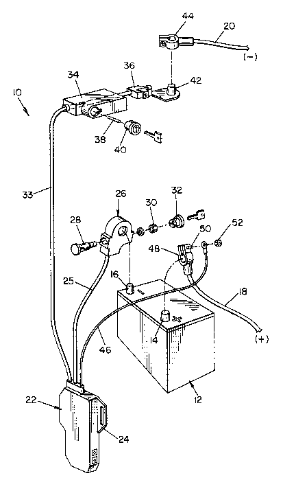
of limiting the invention, FIGURE 1 illustrates the compo-
nent parts of an anti-theft device 10 connectable to a stan-
dard vehicle battery 12 having positive and negative termi-
nals 14 and 16, respectively, for supplying electric current
21 26 73~ JW-~633
through corresponding positive and negative battery cables
18, and 20. Anti-theft device 10 comprises a housing 22
enclosing circuit components to be described hereinafter and
which housing is preferably constructed of suitable plastic
materi.al and provided with one or more mounting tabs 24 by
which the housing can be secured to the vehicle in the en-
gine compartment such as through the use of threaded fasten-
ers or plastic tying straps, not shown.
The anti-theft device is connected to negative battery
terminal 16 by means of a line 25 from housing 22 and ter-
minal clamp 26 which includes a flat headed terminal bolt 28
extending through an opening therefor in clamp 26 to receive
a terminal clamp nut 30 which, when threaded onto bolt 28,
is disposed within clamp 26. The opening through which nut
30 is accessible for mounting and dismounting clamp 26 on
terminal 16 is closed by a key operated plug 32, thus to
preclude unauthor.ized disassembly of the clamp from the bat-
tery terminal. The anti-theft device is connected to the
negative battery cable 20 through a line 33 from housing 22
and a slide lock box 34 to which a box terminal 36 is se-
cured by means of a lock pin 38 and a key operated locking
plug 40. Lock box terminal 36 includes a terminal post 42
adapted to receive clamp 44 on the end of cable 20.
The anti-theft device is connected to the positive ter-
minal of battery 12 by lead 46 from housing 22 which is at-
tached to clamp 48 on the end of battery cable 18 such as by
clamp bolt 50 and clamp nut 52. As will be appreciated from
the description thus far, the anti-theft device can not be
detached from battery 12 by an unauthorized person in that
terminal block 26 requires the use of a key to access the
clamp, bolt and nut assembly. If a would-be thief attempts
to remove terminal block 26 from the battery, battery termi-
nal 16 will be destroyed, thus making it impossible to at-
tach negative battery cable 20 to the terminal. According-
ly, a thief can not disconnect negative battery cable 20
212673~ JW-8633
from terminal 42 and reconnect it to battery terminal 16 so
as to bypass the anti-theft device.
Referring now to FIGURE 2, it will be appreciated that
a vehicle in which anti-theft device 10 is mounted has elec-
trical circuitry including a standard starting circuit com-
prising a starting motor 54, solenoid 56 and an operating or
ignition switch 58. As is well known, when the ignition
switch is closed, solenoid 56 engages starting motor 54 with
the engine flywheel and causes current flow from battery 12
through the s-tarting motor to s~art the vehicle. As is fur-
ther well known, battery 12 drives various electrical compo-
nents schematically illustrated in FIGURE 2 as accessories
60 which include, for example, the vehicle lights, ignition
system, radios, clocks, fans, power equipment, cigarette
lighters and the like, some of which accessories such as
radios and cloclcs include pre-set digital displays and vola-
tile memory which must be continuously energized so as to
avoid having to reset the devices. As is still further well
known, the electrical system in the vehicle includes an al-
ternator 62 for applying current to battery 12 during opera-
tion of the vehicle for purposes of charging the battery.
Anti-theft device 10 is adapted to preclude the unau-
thorized starting of the vehicle in response to closure of
ignition switch 58 and, for this purpose, is provided with a
remotely controllable power switch 64 in housing 22 which,
when open, interrupts current flow from battery 12 to the
starting circuit. More particularly, power switch 64 in-
cludes contacts 66 and 68, respectively on lines 25 and 33
of the anti--theft device, and a jumper bar 70 attached to
plunger 72 of a solenoid 74 by which the jumper bar is dis-
placeable between closed and opened positions relative to
contacts 66 and 68. In the closed, solid line position, of
jumper bar 70 shown in FIGURE 2 the starting circuit is con-
nected across battery 12, and in the open, broken line posi-
tion of the jumper bar the starting circuit is disconnected
JW-8633
~126~3 l
-
from the battery. For the purpose set forth hereinafter, a
resistor 76 and a normally closed bimetal switch device 78
are each connected across lines 25 and 33 in parallel with
power switch 64.
As will be appreciated from FIGURES 2 and 3 of the
drawing, anti-theft device 10 includes a control circuit 80
enclosed within housing 22, and a transmitter 82 for remote-
ly activating control circuit 80 in a manner to achieve
opening and closing of power switch 64. Control circuit 80
includes a receiver-decoder 86 including an antenna 88 for
receiving signals S from antenna 90 of transmitter 82. Con-
trol circuit 80 further includes a reset timer 92 which is
part of a micro-processor, not shown, used in the control
circuit. In accordance with the preferred embodiment,
transmitter 82 provides for passive control of power switch
64 through control circuit 80 and, in this respect, is a
personal identification unit carried by the vehicle owner
and which continuously transmits a series of electromagnetic
coded signals S at short intervals, such as about ten sec-
onds. The coded signals are an arrangement of pulses unique
to the particular transmitter, whereby the latter identifies
an authorized operator of the vehicle. Receiver-decoder 86
of control circuit 80 has a decoding network for recognizing
the unique coded pattern of signals S from transmitter 82,
and the periodic transmission of signals S provides for con-
trol circuit 80 to be activated in accordance with the loca-
tion of transmitter 82 relative to the vehicle. In this
respect, for example, if the operator of the vehicle is
within fifty feet thereof, control circuit 80 will be acti-
vated by signals S whereas, if the operator is beyond fifty
feet, transmitter 82 is outside the range of transmission of
signals S for the purpose of activating control circuit 80.
It will be appreciated of course that the range of transmis-
sion for transmitter 82 can vary in accordance with the
2126734 JW-8633
strength o a battery therein, not shown, by which the
transmitter is powered.
When the operator of the vehicle is within the vicinity
thereof, control circuit 80 is activated to connect solenoid
74 to battery 12 through line 94 to close power switch 64.
At this time, the component parts of the system are in the
solid line positions thereof shown in FIGURE 2 of the draw-
ings. Moreover, control circuit 80 maintains power switch
64 in the closed position so long as the operator remains
within the vicinity of the vehicle. In this respect, sig-
nals S are transmitted to receiver-decoder 86 periodically,
such as every ten seconds, and the decoder, upon recognizing
and acknowledging the unique coded signal from the transmit-
ter, transmits a signal through output 96 to reset timer 92
which has an expiration time greater than the ten second
period between siqnals S and which expiration time is, for
example, thirty seconds. Each time reset timer 92 receives
a signal from output 96, it resets to the full expiration
time thereof. Therefore, if the operator remains in the
vicinity of tlle vehicle, timer 92 continues to reset in re-
sponse to signals S and the component parts remain in the
positions thereof shown in FIGURE 2. When the vehicle oper-
ator leaves the vicinity of the vehicle, signals S are no
longer received by receiver-decoder 86 and, accordingly, the
thirty second expiration time of timer 92 expires without
the timer receiving a reset signal througll output 96. Con-
sequently, timer 92 outputs a signal through line 98 by
which solenoid input line 94 is disconnected from battery
12. Solenoid 74 is therefore de-energized, whereby power
switch G4 moves to the open, broken line position thereof
shown in FIGURE 2 to disconnect battery 12 from the vehicle
starting circuit. When the vehicle owner subsequently moves
back into the vicinity of the vehicle, the first signal S
received by receiver-decoder 86 is outputted through timer
92 via line 98 to again connect solenoid input- line 94 with
-- 10 --
` 2I 2 b~ 7~ ~ JW-8633
battery 12, whereupon the solenoid is energized to close
power switch 64 enabling starting of the vehicle. Subsequent
signals S received by receiver-decoder 86 and outputted
through line 96 to timer 92 operate as described hereinabove
to reset the timer, whereby power switch 64 remains closed
until such time as the operator again leaves the vicinity of
the vehicle.
Preferably, transmitter 82 is provided with a selec-
tively operable pushbutton override 100 to provide for manu-
ally or actively controlling operation of power switch 64
through control circuit 80. In this respect, manual depres-
sion of pushbutton 100 by the vehicle owner provides for
continuous transmission of signals S to receiver-decoder 86
as opposed to the periodic signal transmitted when the
transmitter is operated in the passive mode as described
hereinabove. A continuous signal S from the transmitter,
after decoding and acceptance by receiver-decoder 86, is
outputted by the microprocessor through line 102, bypassing
timer 92, whereby solenoid 74 is directly activated or deac-
tivated. Transmitter 82 can be provided with a switch, for
example, for shifting the transmitter between the active and
passive modes of operation thereof and, when in the active
mode, sequential signals S resulting from sequential depres-
sions of pushbutton 100 are operable through control circuit
80 to sequentially shift the solenoid between the two modes
thereof and, thus, power switch 64 between the open and
closed positions thereof. It will be appreciated, of
course, that transmitter 82 has to be within the transmit-
ting range thereof in the active mode in order for the sig-
nals to be received by receiver-decoder 86. It will be ap-
preciated from the foregoing description that when the vehi-
cle operator is within the transmitting range of transmitter
82 and the component parts of the control circuit are in the
solid line positions thereof shown in FIGUR~ 2, depression
of pushbutton 100 causes power switch 64 to open and move to
212673'1 JW-8633
the broken line position thereof and that the subsequent
depression of pushbutton 100 shifts the power switch back to
its closed position.
With further regard to FIGURES 2 and 3 of the drawing,
when power switch 64 is closed the vehicle can be started by
closing ignition switch 58 in that power switch 64 connects
battery 12 with the starting circuit so as to provide for
the delivery of sufficient current to the starting circuit
to operate starting motor 54. When the engine is started
and running, the control circuit is operable as indicated
by line 104 to maintain solenoid 74 energized and thus power
switcll 64 closed. Should the engine stall, it will be ap-
preciated that power switch 64 will remain closed as the
result of the proximity of transmitter 82 if the latter is
operating in the passive mode, or as a result of the closed
disposition of the switch resulting from the previous de-
pression of pushbutton 100 of the transmitter. Thus, the
vehicle can be restarted when stalled without any action on
the part of the operator other than to restart the engine in
the normal manner through use of the ignition key. However,
if the engine stops and the operator leaves the vehicle,
provision is made to assure opening of power switch 64 in
the event transmitter 82 either fails in the passive mode,
or the operator forgets to depress pushbutton 100 in the
active mode. In this respect, when the engine stops, the
output of alternator 62 also stops, and the control circuit
outputs a signal as indicated by the line 106 indicative of
this condition and which operates through a one-shot timer
108 to output a signal through line 110 to the control cir-
cuit for the purpose of disconnecting solenoid 74 from bat-
tery 12 and thus opening power switch 64 if the engine is
not restarted within a predetermined period of time such as
two minutes determined by timer 108. Thus, if power switch
64 is not opened automatically in response to the movement
of transmitter 82 beyond the transmission range thereof, or
- 12 -
~ 2~2673~ JW-8633
by depression of pushbutton 100 in the active mode of the
transmitter, the switch will be opened through timer 108 so
that the vehicle owner does not leave the vehicle with the
anti-theft device unactivated.
When the vehicle owner leaves the vehicle and activates
anti-theft device 10, thus opening power switch 64, it will
be appreciated -that the vehicle accessories are connected to
battery 12 through resistance 76 which is in parallel with
switch 64. This is important in connection with the acces-
sories that musk continuously operate, such as clocks, and
is extremely important in connection with accessories such
as cloc]cs and radios having pre-set digital displays and
volatile memories which can be lost as the result of inter-
rupting current flow thereto such as would happen with power
switcll 64 open in the absence of resistance 76. To serve
the intended purpose in accordance with the present inven-
tion, resistance 76 provides a current flow sufficient to
maintain the desired pre-sets but which, preferably, is
such that accessories such as the vehicle lights will not
operate normally at the current level thereacross. Thus, in
response to turning the lights on with switch 64 open, the
lights will be dimmer than normal and will lead a would-be
thief to believe that the battery is weak. Importantly too
in accordance with this embodiment of the invention, normal-
ly closed bimetal switch device 7~ which is connected in
parallel with power switch 64, is operable when power switch
64 is open to provide a noise simulating that of a weak bat-
tery upon closure of ignition switch 58 or an effort to by-
pass the latter. In this respect, control circuit 80 re-
sponds to closure of the ignition switch or an effort to
bypass the same by passing current from battery B through
lead 112 across the normally closed bimetal switch 78. In a
well known manner, the latter is heated by such current flow
and thus deflected from the closed to the opened, broken
line position shown in FIGURE 2 and, upon cooling, returns
- 13 -
21 2 6 73 l JW-~633
-
to the closed position whereupon the current flow
thereacross causes the switch to open again. Accordingly,
it will be appreciated that the device operates in the man-
ner of a vehicle turn signal flasher control and that both
the timing of the repetitiveness of opening and closing as
well as the level and tone of the sound produced thereby can
be designed for simulating the chatter which is heard when
an effort is made to start a vehicle having a weak battery.
Thus, a would-be thief not only can not start the vehicle
but also is led to believe that the vehicle battery is weak,
whereby the attempted theft will normally be abandoned.
FIGURE 4 illustrates an embodiment of the anti-theft
device equivalent to those disclosed in the aforementioned
patent to Carlo et al and in particular to the embodiment of
FIGURE 6 in the latter patent. In this respect, anti-theft
device 10' includes a power switch 114 comprising terminals
116 and 118 interposed in battery cable 120, and a jumper
bar 122 which is reciprocated by a relay coil 124 under the
control of a control circuit 126. The control circuit in-
cludes a receiver-decoder 12~ having an antenna 130 which
receives the coded command signals S' from remote transmit-
ter ~2' WhiCIl iS operated in the active mode in this em-
bodiment. ~s described in the Carlo et al patent, power
switch 114 is normally closed and, when the anti-theft de-
vice is activated, opens and closes in response to an effort
to start the engine, thus producing a chattering noise simu-
lating that of a weak battery. The opening of power switch
114 is in response to high current flow through battery ca-
ble 120, and the current in battery cable 120 is measured by
a surrounding inductor coil 132 having leads connected to
control circuit 126. When switch 114 opens, control circuit
126 senses no current flow and this allows switch 114 to
close after a predetermined time and then to reopen when
circuit 126 aqain receives an input signal from coil 132.
- 14 -
212~73~ JW-~633
Thus, an unauthorized person cannot start the vehicle en-
glne .
As will be further appreciated from the Carlo et al
patent, control circuit 126 includes a lockout or override
circuit adapted to be operated by transmitter 82' so as to
preclude opening of power switch 114 in response to high
current flow through battery cable 120, whereby the vehicle
owner can start the vehicle. More particularly, transmitter
~2' transmits signal S' to antenna 130 of receiver-decoder
12~ of control circuit 126 which then operates to maintain
power switch 114 closed for a predetermined period of time
during which the vehicle owner must enter the vehicle and
start the engine. If this time is exceeded, the override
circuit is deactivated and the vehicle owner must again de-
press transmitter button 100' to again activate the override
for another time period. Once the vehicle is started, con-
trol circuit 126 functions to maintain power switch 114
closed. Should the engine stall, control circuit 126 oper-
ates to provide a period of time during which the vehicle
owner can restart the engine without power switch 114 open-
ing and closing in response to such a starting effort. For
example, as described hereinabove in conjunction with the
em~odiment of FIGURES 1-3, the vehicle alternator can be
employed to detect the stall condition and to initiate tim-
ing of a period, such as two minutes, for restarting the
engine .
In accordallce witll one aspect of the present invention,
anti-theft device 10' i5 provided with a resistance 134
across hattery cable 120 in parallel with power switch 114.
Accordingly, when power switch 114 opens and closes in re-
sponse to an effort to start the vehicle engine when the
anti-theft device is activated, resistance 134 maintains
electrical accessories of the vehicle connected to the bat-
tery. Thus, if a would-be thief attempts to start the vehi-
cle by closing the ignition switch or jumping the latter,
JW-8633
212673~
the thief is deterred by the chattering noise of power
switch 114 which leads the thief to believe that the battery
is weak. At the same time, resistance 134 assures that the
pre-sets will not dropout during such a starting effort.
While considerable emphasis has been placed herein on
the preferred embodiment illustrated and described hereina-
bove, it will be appreciated that other embodiments of the
invention can be made and that changes can be made in the
preferred embodiment without departing from the principals
of the present invention. Accordingly, it is to be dis-
tinctly understood that the foregoing descriptive matter is
to be interpreted merely as illustrative of the invention
and not as a limitation.
- 16 -