Language selection

Search

Patent 2126858 Summary

Third-party information liability

Some of the information on this Web page has been provided by external sources. The Government of Canada is not responsible for the accuracy, reliability or currency of the information supplied by external sources. Users wishing to rely upon this information should consult directly with the source of the information. Content provided by external sources is not subject to official languages, privacy and accessibility requirements.

Claims and Abstract availability

Any discrepancies in the text and image of the Claims and Abstract are due to differing posting times. Text of the Claims and Abstract are posted:

  • At the time the application is open to public inspection;
  • At the time of issue of the patent (grant).
(12) Patent: (11) CA 2126858
(54) English Title: ARTICULATED DOCUMENT FEEDER
(54) French Title: DISPOSITIF D'ALIMENTATION EN DOCUMENTS ARTICULE
Status: Expired and beyond the Period of Reversal
Bibliographic Data
(51) International Patent Classification (IPC):
  • B65H 29/60 (2006.01)
  • B65H 5/06 (2006.01)
  • B65H 29/58 (2006.01)
(72) Inventors :
  • DRISCOLL, JAMES N. (United States of America)
  • DRAGO, MICHAEL RICHARD (United States of America)
(73) Owners :
  • BELL AND HOWELL, LLC
(71) Applicants :
  • BELL AND HOWELL, LLC (United States of America)
(74) Agent: KIRBY EADES GALE BAKER
(74) Associate agent:
(45) Issued: 1999-09-14
(86) PCT Filing Date: 1993-02-16
(87) Open to Public Inspection: 1993-08-19
Examination requested: 1995-01-16
Availability of licence: N/A
Dedicated to the Public: N/A
(25) Language of filing: English

Patent Cooperation Treaty (PCT): Yes
(86) PCT Filing Number: PCT/US1993/001395
(87) International Publication Number: WO 1993015987
(85) National Entry: 1994-06-27

(30) Application Priority Data:
Application No. Country/Territory Date
835,412 (United States of America) 1992-02-14

Abstracts

English Abstract


Document diverter assemblies (6, 8) are spaced transversely for altering the
flow of documents through a handling apparatus.
Each of the diverter assemblies have respective housing (16, 18) which can
pivot about axes (B). Each housing supports respective
sets of idle rolls (24, 26, 28, 30) which contact a drive roller (36).
Compliance members, in the form of O-rings are mounted
on the idle rollers.


French Abstract

Des ensembles de déviation (6, 8) de documents sont espacés transversalement pour modifier le cours de documents dans un appareil de manipulation. Chacun des ensembles de déviation comporte un logement respectif (16, 18) pouvant pivoter autour d'axes (B). Chaque logement supporte des ensembles respectifs de rouleaux libres (24, 26, 28, 30) venant au contact d'un cylindre d'entraînement (36). Des éléments conférant de la souplesse, se présentant sous la forme de joints toriques, sont montés sur les rouleaux libres.

Claims

Note: Claims are shown in the official language in which they were submitted.


CLAIMS:
1. In document feeding apparatus including idle rollers
cooperating with drive roller means, said idle rollers spaced along
the axis of rotation of the idle rollers and transversely to the
document feed direction, the improvement comprising:
first housing means for supporting a first set of
transversely spaced idle rollers, and
first means, including a pivot bearing, allowing the first
housing means and the first set of idle rollers supported thereby to
pivot about an axis that is perpendicular to the axis of rotation of
said first set of idle rollers, and
drive roller means cooperating with said first set of idle
rollers whereby each one of said first set of idle rollers retains a
cooperative relationship with the drive roller means despite
unevenness in a contact face between an idle roller and the drive
roller means, and
resilient compliance means on the idle rollers adapted for
maintaining surface contact with the drive roller means.
2. Apparatus according to claim 1, further including a second
set of idle rollers supported by said first housing means and
pivot means for allowing said second set of idle rollers to
pivot between first and second positions around the axis of rotation
of said first set of idle rollers.
3. Apparatus according to claim 2, further including:
second housing means for supporting a third set of
transversely spaced idle rollers; and
second means, including a pivot bearing, allowing the
second housing means and the third set of idle rollers supported
thereby to pivot about an axis that is perpendicular to the axis of
rotation of said second set of the idle rollers, and

idle rollers retains a cooperative relationship with the
drive roller means despite unevenness in the contact face.
4. Apparatus according to claim 2, wherein said pivot
means further include solenoid means which, when actuated,
causes said second set of idle rollers to pivot between
first and second positions.
5. Apparatus according to claim 3 wherein said first
and second housing means are spaced transversely along the
axis of rotation of the idle rollers.
6. Apparatus according to claim 1 wherein said
compliance means comprise resilient O-rings mounted on the
periphery of said first set of transversely spaced idle
rollers.
7. Apparatus according to claim 2 wherein said
compliance means comprise resilient O-rings mounted on the
periphery of said second set of transversely spaced idle
rollers.
8. Apparatus according to claim 7 wherein the O-rings
mounted on the periphery of said first set of transversely
spaced idle rollers have a hardness differing from the
hardness of the resilient O-rings mounted on the periphery
of said second set of transversely spaced idle rollers.
9. Apparatus according to claim 8 wherein the
hardness of the O-rings mounted on the periphery of said
first set of transversely spaced idle rollers is greater
than the hardness of the O-rings mounted on the periphery of
said second set of transversely spaced idle rollers.
-8-

Description

Note: Descriptions are shown in the official language in which they were submitted.


CA 02126858 1999-OS-27
ARTICULATED DOCUMENT FEEDER
Field of the Invention
This invention relates to document feeders; and, more
particularly, the invention relates to a document feeder
which has the capability of both adapting to non-
uniformities of document feeder parts and of altering the
flow path of a document propagated through a document
handling apparatus.
BACRl3ROUND AND OBJECTS OF THE INVENTION
Document feeding mechanisms in document handling
apparatus are generally characterized by at least one,
preferably more, drive rollers which pinch a document
between the drive rollers) and so-called idle rollers. As
the rollers rotate, a document pinched between them will be
propagated. Preferably a plurality of idle rollers
cooperating with at least one drive roller are disposed
transversely to the direction of document propagation. Due
to asymmetries between respectively cooperating drive and
idle rollers, caused either initially by manufacturing
tolerances, or subsequently by uneven wear, irregular,
or asymmetric, feeding of the documents can result with
consequent jams which lead to undesirable down-time of the
document handling apparatus.
Accordingly, it is a primary object of this invention
to minimize the consequences of asymmetries between
cooperating idle, and drive, rollers.
The problems of asymmetry between cooperating idle,
and drive, rollers become more acute when the document feeding
-1-

WO 93/15987 PCT/US93/01z95
apparatus is also asked to perform a second function, in
I; addition to document feeding. When a document feeding mechanism
1
l;is also used to alter, or divert, the flow path of a document to
ii
is different destination within the document handling apparatus, '
,, the repetitive motion resuired to rereatedly alter the direction'
~iof document motion will cause a build-up of wear likely to
n
Ilresult in undesirable asymmetry.
I Accordingly, it is another object of this invention to
I
I~provide a document feeding and diverting device which adapts
1~ Ilitself automatically to uneven wear between respective idle, and
;Idrive, roller assemblies.
i! A common form of diverting apparatus generally adds to
~a first set of idle rollers always in contact with drive
'roller(s) a second set of idle rollers spaced from the first set
along the direction of document propagation. h'hen a divert path
for the document is desirable, the second set of idle rollers is
,also brought into temporary engagement with the periphery of the
drive rollers) by pivoting the second set about an axis that is
the axis of rotation of the first set of idle rollers. Because
such temporary engagements of the second set of idle rollers
with the drive rollers) occurs suddenly and with some rapidity,
it is necessary to allow for some damping or compliance means
between the second set of idle rollers and the drive rollers)
to lessen, or absorb, the shocks created by such rapid
2 ~, engagement .
_2_

WO 93/15987 PCT/US93/01395
.-. ~ II
Accordingly, it is another object of this invention to
provide a document feeding and diverting device which provides
;;for damping the sudden contact when a second set of idle rollers
~iis rapidly brought into contact with a drive roller surface.
SUMMARY OF THE INVENTION
In a preferred embodiment of the invention, the
document feeding and diverting assembly comprises a pair of two
sets of idle rollers spaced transversely to the feeding
direction of a document. A first set of two transversely spaced
10'idle rollers of each of the pairs is always in contact with at
least one drive roller, while a second set of two transversely
spaced idle rollers is pivotable about a first axis into
engagement with the drive roller when a document divert
operation is desired. The first axis is the axis of rotation of
~~the first set of two idle rollers. In addition to being
pivotable about the first axis, each of the two sets of idle
rollers is articulated to be also pivotable about a second axis,
the second axis being perpendicular to the first axis.
As a result of the articulation, a set of idle rollers
~~spaced transversely along the axis of rotation is thus able to
"hug" the contours of the corresponding set of drive rollers,
even if those contours should be asymmetric, i.e. differ along
the periphery of the rollers.
To assure that the idle rollers remain in surface
°25 ~~contact with the drive roller(s), regardless of surface
discontinuities between their contact faces, compliance means
-3-

WO 93/15987 PCT/US93/01 zQ5
are provided. These compliance means preferably comprise
resilient 0-rings mounted across the peripheral surface of the
idle rollers. To account for the variable contact forces
between, respectively, the first and second set of idle rollers '
i~and the drive roller(s), the first set of idle rollers has O-
rings which have a higher hardness than the O-rings mounted on
the periphery of the second set of idle rollers.
While the invention is illustrated in combination with
a preferred embodiment in which the document feeding apparatus
j~also functions as a document diverting apparatus, the invention
is not so limited because the asymmetries to be described in
greater detail will also arise in document feeding apparatus
which has no diverting function.
The foregoing and other objects, features and
j~advantages of the invention will be apparent from the following
more particular description of several preferred embodiments of
the invention, as illustrated in the accompanying drawings.
BRIEF DESCRIPTION OF THE DRAWINGS
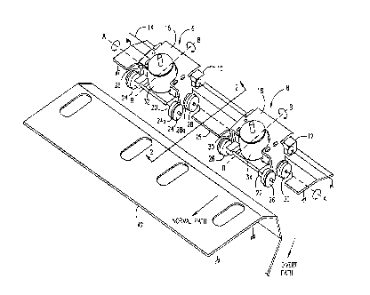
Fig. 1 is a partially isometric, partially schematic,
~~view of two document feeding assemblies, with certain details
omitted for purposes of clarity; and,
Fig. 2 is a view of the apparatus shown in Fig. 1,
along the line 2-2.
Fig. 3 is a simplified schematic view of the operation
of the pivot mechanism with grossly exaggerated surface
irregularities.
-4-

WO 93/15987 ~ ~ PCf/US93/01395
DETAILED DESCRIPTION OF THE INVENTION
With reference to Fig. 1, two diverter assemblies 6, 8
' ~~are spaced transversely along an axis of rotation A-A. Hollow
~~bearing sleeves 10, 12 are supported by a shaft 14, indicated
schematically, which is firmly fixed to the document handling
apparatus (not shown, for purposes of clarity). Each of the
diverter assemblies 6, 8 is comprised of respective housings 16,
18 through which the bearing sleeve 10 projects, as at C (see
Fig. 2) to thereby create a pivot bearing, so that the
respective housings 16 ,18 can pivot about the axes B-B.
Also mounted on the respective housings I6, 18 are
respective idle roller carriages 20, 22 each of which,
respectively, rotatably supports respective sets of idle rollers
24, 26. Each housing 16, 18 also supports respective sets of
idle rollers 28, 30 (of which one is only partially shown
because of the isometric view). However, it is to be
understood, that each housing 16, 18 also has an idle roller
spaced transversely from respective idle rollers 28, 30. Each
of the sets of idle rollers 24, 26, 28 and 30 preferably has
resilient O-rings, such as shown at 24a and 28a, surrounding
their periphery. To account for the different loading of the
respective sets of idle rollers O-rings) 24a are preferably
made of a silicon, or fluorosilicon, compound having a rating of
50 Shore A Durometer, while O-rings) 28a are preferably made of
a cast polyurethane compound having a rating of 70 Shore A
Durometer. The O-rings constitute, and function as, compliance
-5-

means between the contact face of idle and drive rollers and
have a preferable thickness of about 3/32".
Respective solenoids 32, 34 are also supported by the
respective housings 16 and 18 so that, upon actuation thereof,
the respective pairs of idle rollers 24 and 26 are caused to
pivot about axis A-A from a first position, as shown in Fig. 1,
to a second position 24', as shown in Fig. 2, for the purposes
to be hereinafter described.
Not shown in Fig. 1, but shown in Fig. 2, each of the
respective sets rollers 28, 30 (and their partially shown
transverse partners) have paired therewith a cooperating drive
roller 36, as shown in Fig. 2.
With reference to Fig. 2, in which parts
corresponding to Fig. 1 have the identical designation, each
solenoid, such as 32, is comprised of a plunger 38 so that,
when plunger 38 is actuated by solenoid 32, the idle roller
carriage 20, pivotably supported in housing 16, is caused to
pivot from the position shown in solid lines in Fig. 2 to the
position indicated in dotted lines in Fig. 2, i.e. idle rollers
24 pivot about axis A-A to assume the position indicated at
24', to thus divert a document from its normal path along the
surface of support plate 42 to an alternate, divert path.
Upon deenergization of solenoid 32, a return spring
40 returns the idle roller carriage to the position shown in
Figs. 1 and 2 to cause document feeding along the normal path
indicated.
-6-
;~.~.

CA 02126858 1999-OS-27
In operation, and as shown schematically in Fig. 3,
each diverter assembly 6 and 8, having respective idle
rollers 30, has cooperating therewith a drive roller 36.
By virtue of the structure shown and described in Figs. 1
and 2, any wear and tear causing asymmetrical contact faces
between the respective idle rollers 30 and drive roller 36,
is compensated for by allowing the idle rollers 30, to
pivot about the pivot point C and axis B-B to thereby
assure that contact is maintained between at least one~pair
of drive and idle rollers regardless of unevenness between
their contact faces. Thus, if, for example, drive roller
36 has a depression (shown grossly exaggerated in at D Fig.
3) on its periphery, idle roller 30 will be able to track
the depression by the pivotal movement about C of the
housing containing idle rollers 30.
While the preferred embodiment of the invention has
been illustrated as comprising two articulated document
feeders, which preferably also function to divert
documents, the invention is not so limited. Clearly, for
appropriately dimensioned documents, only one assembly,
i.e. 16, may be sufficient to adequately feed a document.
Likewise, if no document diversion is desired, the feature
allowing the pivotal motion of the respective sets of idle
rollers 24 (or 26) may be dispensed with.
While the invention has been particularly shown and
described with reference to a preferred embodiment thereof,
it will be understood by those skilled in the art that. the

WO 93/15987 PCT/US93/0' z95
foregoing and other changes in form and details may be made
therein without departing from the spirit and scope of the
invention, as defined in the claims appended hereto.
_g_

Representative Drawing
A single figure which represents the drawing illustrating the invention.
Administrative Status

2024-08-01:As part of the Next Generation Patents (NGP) transition, the Canadian Patents Database (CPD) now contains a more detailed Event History, which replicates the Event Log of our new back-office solution.

Please note that "Inactive:" events refers to events no longer in use in our new back-office solution.

For a clearer understanding of the status of the application/patent presented on this page, the site Disclaimer , as well as the definitions for Patent , Event History , Maintenance Fee  and Payment History  should be consulted.

Event History

Description Date
Letter Sent 2011-07-27
Inactive: IPC from MCD 2006-03-11
Time Limit for Reversal Expired 2006-02-16
Letter Sent 2005-02-16
Inactive: Late MF processed 2002-05-10
Letter Sent 2002-02-18
Inactive: Late MF processed 2001-03-19
Letter Sent 2001-02-16
Grant by Issuance 1999-09-14
Inactive: Cover page published 1999-09-13
Pre-grant 1999-05-27
Inactive: Final fee received 1999-05-27
Inactive: Received pages at allowance 1999-05-27
Letter Sent 1998-12-01
Notice of Allowance is Issued 1998-12-01
Inactive: Status info is complete as of Log entry date 1998-11-24
Inactive: Application prosecuted on TS as of Log entry date 1998-11-24
Inactive: Approved for allowance (AFA) 1998-11-03
All Requirements for Examination Determined Compliant 1995-01-16
Request for Examination Requirements Determined Compliant 1995-01-16
Application Published (Open to Public Inspection) 1993-08-19

Abandonment History

There is no abandonment history.

Maintenance Fee

The last payment was received on 1999-01-20

Note : If the full payment has not been received on or before the date indicated, a further fee may be required which may be one of the following

  • the reinstatement fee;
  • the late payment fee; or
  • additional fee to reverse deemed expiry.

Please refer to the CIPO Patent Fees web page to see all current fee amounts.

Fee History

Fee Type Anniversary Year Due Date Paid Date
MF (application, 5th anniv.) - standard 05 1998-02-16 1998-02-02
MF (application, 6th anniv.) - standard 06 1999-02-16 1999-01-20
Final fee - standard 1999-05-27
MF (patent, 7th anniv.) - standard 2000-02-16 2000-01-31
Reversal of deemed expiry 2002-02-18 2001-03-19
MF (patent, 8th anniv.) - standard 2001-02-16 2001-03-19
Reversal of deemed expiry 2002-02-18 2002-05-10
MF (patent, 9th anniv.) - standard 2002-02-18 2002-05-10
MF (patent, 10th anniv.) - standard 2003-02-17 2003-01-17
MF (patent, 11th anniv.) - standard 2004-02-16 2004-02-09
Registration of a document 2011-07-08
Owners on Record

Note: Records showing the ownership history in alphabetical order.

Current Owners on Record
BELL AND HOWELL, LLC
Past Owners on Record
JAMES N. DRISCOLL
MICHAEL RICHARD DRAGO
Past Owners that do not appear in the "Owners on Record" listing will appear in other documentation within the application.
Documents

To view selected files, please enter reCAPTCHA code :


To view images, click a link in the Document Description column. To download the documents, select one or more checkboxes in the first column and then click the "Download Selected in PDF format (Zip Archive)" or the "Download Selected as Single PDF" button.

List of published and non-published patent-specific documents on the CPD .

If you have any difficulty accessing content, you can call the Client Service Centre at 1-866-997-1936 or send them an e-mail at CIPO Client Service Centre.


Document
Description 
Date
(yyyy-mm-dd) 
Number of pages   Size of Image (KB) 
Cover Page 1995-09-09 1 19
Claims 1995-09-09 2 97
Abstract 1995-09-09 1 55
Drawings 1995-09-09 2 50
Description 1995-09-09 8 361
Abstract 1998-10-07 1 50
Description 1998-10-07 8 300
Claims 1998-10-07 2 79
Drawings 1998-10-07 2 44
Representative drawing 1999-09-07 1 15
Description 1999-05-27 8 300
Cover Page 1999-09-07 1 46
Commissioner's Notice - Application Found Allowable 1998-12-01 1 163
Maintenance Fee Notice 2001-03-19 1 176
Late Payment Acknowledgement 2001-03-22 1 169
Maintenance Fee Notice 2002-03-18 1 179
Late Payment Acknowledgement 2002-05-24 1 172
Maintenance Fee Notice 2005-04-13 1 172
Correspondence 1999-05-27 3 124
Correspondence 1998-12-01 1 103
Fees 1997-02-14 1 60
Fees 1996-02-15 1 52
Fees 1995-02-13 1 62
International preliminary examination report 1994-06-27 16 451
PCT Correspondence 1995-11-09 1 45
Prosecution correspondence 1995-01-16 1 38
Prosecution correspondence 1998-07-28 2 88
Prosecution correspondence 1995-04-11 1 24
Courtesy - Office Letter 1995-02-10 1 49
Courtesy - Office Letter 1994-12-19 1 58
Courtesy - Office Letter 1995-09-11 1 33
Examiner Requisition 1998-02-06 2 59