Note: Descriptions are shown in the official language in which they were submitted.
r
2127061
1525 (203-583 CIP II)
SELF CONTAINED GAS POWERED SURGICAL APPARATUS
10
HACRGROUND OF THE INVENTION
1. Field of the Invention
This invention relates to surgical stapling
apparatus, and more particularly to surgical apparatus
which are powered by self contained relatively low pressure
gas systems to perform sequential operations such as tissue
clamping, staple forming and/or tissue cutting.
2. Description of Related Art
Surgical stapling apparatus is known wherein
tissue is first grasped or clamped between opposing jaw
structure and then fastened by means of fasteners. In some
instruments a knife is provided to cut tissue which has
been joined. The fasteners are typically in the form of
surgical staples however, two part polymeric type fasteners
are also known.
Instruments for this purpose can comprise two
elongated fingers which are respectively used to capture or
clamp tissue. Typically, one of the fingers carries a
disposable cartridge housing a plurality of staples
arranged in at least two lateral rows while the other
finger comprises an anvil for curling the staple legs into
hook form upon their being driven against the anvil. The
X21 27~~~
-2-
stapling operation is effected by a pusher which travels
longitudinally along the cartridge carrying finger, with
the pusher acting upon the staples to place rows of staples
in body tissue. A knife may optionally be positioned to
operate sequentially immediately behind the pusher and
laterally positioned between the staple rows longitudinally
cut and/or open the stapled tissue between the rows of
staples. Such instruments are disclosed in Bobrov et al.
(U.S. Pat. No. 3,079,606) and Green (U.S. Pat. No.
3,490,675). The instruments disclosed therein comprise
apparatus for simultaneously making a longitudinal incision
and applying a row of staples on both sides of an incision.
A later development disclosed in Green (U. S. Pat.
No. 3,499,591) applies a double row of staples on each side
of the incision. This is accomplished by a cartridge
assembly wherein a cam member moves within a guide path
between two sets of staggered staple carrying grooves.
Staple drive members located within the grooves each have
two staple pusher plates, and sloping surfaces disposed
within the guide path so as to be contacted by the
longitudinally moving cam and be driven along the groove to
effect ejection of two staples.
The cartridge assemblies typically come in a
plurality of sizes, each varying in both length and number
of staples contained therein. Depending on the procedure
to be performed, the surgeon must select the appropriate
cartridge assembly. No provision is currently available to
adjust the firing means of the instrument itself so that a
wide variety of staple driving sequences may be
accomplished using a single staple cartridge assembly.
The instruments described above were all designed
to be used in surgical procedures wherein surgeons have
_2127061
-3-
direct manual access to the operation site. However, in
endoscopic or laparoscopic procedures surgery is performed
through a small incision or through narrow cannulae
inserted through small entrance wounds in the skin. In
order to address the specific needs of endoscopic and/or
laparoscopic surgical procedures, an endoscopic surgical
stapling apparatus such as that shown in Green et al. (U. S.
Pat. No. 5,040,715) has been developed. This apparatus is
well suited for such procedures and incorporates a distal
end having an anvil and staple cartridge assembly and a
manually operated handle assembly interconnected by an
endoscopic portion which permits the instrument to be
inserted into a cannula and be remotely operated by the
surgeon.
The instruments discussed above all require some
degree of manually applied force in order to clamp, fasten
and/or cut tissue. This manual application can prove
awkward or difficult depending upon the orientation of the
instrument relative to the surgeon, the type of tissue
being operated on or the strength of the surgeon.
Furthermore, because of the difficulty and expense of
cleaning and sterilizing surgical instruments between uses,
there is increasing interest in and demand for instruments
which are disposable after use in a single surgical
procedure rather than permanent and reusable. And because
of the greater convenience and ease of using self-powered
instruments as well as the more uniform results typically
produced by self-powered instruments (as compared
especially to manually powered instruments), there is
increasing interest in and demand for instruments which are
self-powered. Accordingly, there is a need for a self
21 270 61
-4-
powered endoscopic surgical apparatus to alleviate these
difficulties.
Self contained gas powered surgical staplers are
known, as shown, for example, in U.S. Pat. Nos. 3,618,842;
3,643,851; 3,662,939; 3,717,294; 3,815,476; and 3,837,555.
Typically, these staplers include a replaceable cylinder
which supplies gas (e.g., carbon dioxide or nitrogen) at
relatively high pressure (e. g., 800 p.s.i.g.) for powering
the instrument. The high pressure gas used in these
staplers requires that the staplers be of relatively heavy
construction in order to safely accommodate the high
pressure involved. Because of their construction, these
instruments are relatively expensive to manufacture and
therefore generally intended to be relatively permanent and
reusable.
Use of a relatively low pressure gas is
advantageous to enable a stapler to be made of lighter
construction and less expensive materials. This is
desirable to lower the cost and make the stapler
economically disposable. The stapler must, however, be
capable of generating the substantial forces required to
form the staples. Typically, the staples are metal wire
which is partially formed prior to use and which must be
further formed (e.g., crimped against an anvil) by the
stapler. To generate the relatively large forces required
to form the staples with low pressure gas would ordinarily
require a relatively large pneumatic actuator. This is
undesirable because a large actuator makes the stapler
bulky and difficult to work with. In addition, a large
actuator unnecessarily consumes a large amount of gas
during the portion of actuator motion when relatively large
forces are not required, i.e., during the first part of the
21 270 61
- 5 -
actuator stroke when the staple is merely being advanced to the
staple forming position. The gas which is thus effectively
wasted substantially reduces the number of stapling operations
which can be performed by the stapler before its gas supply is
exhausted. This substantially shortens the useful life of the
stapler if the gas supply is not replaceable, and even if the
gas supply is replaceable, it undesirably increases the
frequency with which the gas supply must be replaced.
Although it is desirable to perform most of the
functions of the stapling apparatus automatically using the
self-powering elements in the apparatus, it may also be
desirable for the initial function to be at least partly
manual. For example, if the initial function is tissue
clamping, it is preferably initiated manually so that it can
be performed slowly and precisely and the results inspected and
corrected if necessary before the automatic self-powered
portion of the operating sequence begins. See, for example,
U.S. Pat. Nos. 4,349,028 and 4,331,277 to Green.
Accordingly, there is a present need for a self
contained gas powered surgical instrument for driving surgical
fasteners into body tissue which instrument can be made of
lighter materials and can be made disposable after use.
SUMMARY OF THE INVENTION
Because endoscopic procedures are more common than
laparoscopic procedures, the present invention shall be
discussed in terms of endoscopic procedures and apparatus.
However, use herein of terms such as "endoscopic",
"endoscopically" and "endoscopic portion", among others, should
not be construed to limit the present invention to a stapling
~a;:;
21 270 61
- 6 -
and cutting apparatus for use only in conjunction with an
endoscopic tube. To the contrary, it is believed the present
invention may find use in any procedure where access is limited
to a small incision, including but not limited to laparoscopic
procedures. Also, as used herein the terms "fasteners" and
"staples" shall be treated equivalently. Unless otherwise
stated, the term "cartridge assembly" shall include at least
the cartridge itself and staples or fasteners and staple drive
members disposed therein.
In accordance with an embodiment of the present
invention there is provided a cartridge assembly for a surgical
instrument comprising: a) a housing defining a proximal portion
configured for reception in the surgical instrument and a
distal portion configured for receiving a cartridge: b) a
cartridge disposed in the distal portion of the housing and
defining a proximal end, a distal end, a tissue contacting
surface, and a plurality of transverse slots each for
containing a surgical fastener: c) a staple pusher disposed in
each of the slots for ejecting the surgical fasteners d) a
caroming mechanism movable from the proximal end of the
cartridge to the distal end of said cartridge to sequentially
actuate the staple pushers; e) a knife member adapted to move
through the cartridge with the caroming mechanism while a
cutting edge thereof intersects the tissue contacting surface;
and f) means for moving the cutting edge out of intersection
with the tissue contacting surface when the knife member
approaches the distal end of the cartridge to inhibit external
exposure of the cutting edge.
A self contained endoscopic surgical instrument is
disclosed which is at least partially operable by means of a
relatively low pressure pneumatic assembly. Advantageously,
2 ~ 270 61'
the surgical instrument is a surgical stapling apparatus
adapted for placing one or more longitudinal rows of staples.
This apparatus may further include a knife for making an
incision in body tissue between rows of staples. The latter
configuration may find particular use of adjoining two hollow
organs or in removing an organ, such as the appendix, the
gallbladder, etc. When a knife is employed, means may be
provided for inhibiting external exposure with the cutting edge
thereof following a tissue cutting procedure.
The self contained gas powered surgical instrument
in an endoscopic stapler configuration comprises a frame: an
endoscopic portion defining a longitudinal axis and extending
distally from the frame, the endoscopic portion including an
elongated housing having a distal member for mounting a
cartridge assembly. The cartridge assembly includes a
plurality of surgical staples slidably mounted therein and has
a tissue engaging surface. An anvil member is also provided
and has a staple forming surface and a proximal end mounted to
the elongated housing such that the anvil member is movable
between an open position and a closed position such that the
staple forming surface is in close cooperative alignment with
the tissue engaging surface of the cartridge assembly. The
instrument further includes structure for moving the anvil
member between the open and the closed positions and structure
for ejecting the surgical staples from the cartridge assembly
to cause the staples to engage and form on the staple forming
surface of the anvil member.
A self contained pneumatic system is disposed in the
frame and includes a supply of relatively low pressure gas
contained within a canister and connected to a pneumatic
actuator mechanism which includes a valve assembly. The
pneumatic actuator mechanism actuates the structure for
ejecting the surgical staples from the cartridge assembly. In
_21270~~
_$_
another preferred embodiment means are provided for selectively
controlling relative approximation of the canister and the
valve assembly to prevent premature actuation of the instrument
during shipment. The control means is movable between a first
position in which relative approximation of the canister and
the valve assembly is inhibited and a second position in which
relative approximation of the canister and the valve assembly
is permitted.
The stapler embodiment is preferably controlled by
a manually operable trigger or other similar control.
Momentary operation of the trigger initiates an operating cycle
of the stapler which normally is automatically completed
without continued actuation of the trigger. A safety interlock
may also be employed in cooperation with the trigger mechanism
to prevent accidental actuation. Preferably the stapler
performs only one operating cycle in response to each operation
of the control regardless of the length of time the control is
operated beyond the time required to initiate an operating
cycle. The stapler also cannot begin a new operating cycle
until the preceding cycle is complete. Also, a safety
mechanism may be incorporated to prevent closure of the jaws
if they are misaligned or improperly inserted. In a
particularly preferred embodiment, the operating cycle will not
begin unless sufficient gas remains in the reservoir to propel
the instrument through a complete cycle. Alternatively,
structure may be provided to give a visual or tactile
indication of the number of times the instrument has been fired
and/or lock out the operating cycle after a given number of
firings. Sealing means may be provided to more efficiently
seal the apparatus and prevent excess gas from passing through
the interior thereof.
z~ z~os~~
_ g _
In another particularly advantageous embodiment the
surgical element includes adjustment structure which permits
the instrument to be selectively preset to fire in a
predetermined sequence to drive a given number of staples
and/or rows of staples.
The self contained gas powered surgical instrument
may be constructed either as a reusable unit or as a single
use, disposable unit or, alternatively may be formed with a
reusable handle portion and replaceable staple carrying
cartridges.
Further features of the invention, its nature and
various advantages will be more apparent from the accompanying
drawing and the following detailed description of the
invention.
BRIEF DESCRIPTION OF TAB DRAWINGS
Preferred embodiments of the invention are described
hereinbelow with reference to the drawings. In the drawings
and the description which follows, "proximal" means the end
closest to the operator and "distal" means the end furthest
from the operator.
Fig. 1 is a perspective view of a self contained gas
powered endoscopic surgical instrument in accordance with one
embodiment;
Fig. 2 is an exploded perspective view of the frame
and pneumatic assembly of the surgical instrument of Fig. 1:
Fig. 3 is an exploded perspective view of the
endoscopic portion of the surgical instrument of Fig. 1;
21 27061
- i0 -
Fig. 3A is a side plan view in partial cut away of
the pusher washers and flange member of the pneumatic system
in accordance with one embodiment;
Fig. 4 is an exploded perspective view of one
embodiment of the anvil and cartridge assembly of the surgical
instrument of Fig. 1;
Fig. 5 is a side plan view in cross-section taken
along line 5-5 of Fig. 1 showing the frame and pneumatic
assembly in the unclamped and unfired position;
Fig. 6 is a transverse view in cross-section taken
along line 6-6 of Fig. 5 oriented toward the proximal end of
the instrument showing the frame and pneumatic assembly in the
unclamped position;
Fig. 7 is a side plan view in cross-section showing
the frame and pneumatic assembly in the clamped and unfired
position;
Fig. 8 is a transverse view in cross-section taken
along line 8-8 of Fig. 7 oriented toward the proximal end of
the instrument showing the frame and pneumatic assembly in the
clamped and unfired position:
Fig. 9 is a top plan view in cross-section taken
along line 9-9 of Fig. 5 showing the frame and pneumatic
assembly of the surgical instrument:
Fig. 10 is a transverse view in cross-section taken
along line 10-10 of Fig. 5 oriented toward the distal end of
the instrument showing a portion of the frame and pneumatic
assembly:
a~ .~
2927061
- 11 -
Fig. 11 is a side plan view in cross-section showing
the frame and pneumatic assembly in the clamped and fixed
position:
Fig. 12 is a side cut away view in cross-section
showing the operation of the pneumatic assembly as it is fired;
Fig. 13 is a side cut away view in cross-section
taken along line 13-13 of Fig. 12 showing the valve and gas
tube of the pneumatic assembly:
Fig. 14 is a side plan view in cross-section showing
the frame and pneumatic assembly of a surgical instrument
incorporating an adjustable stroke mechanism:
Fig. 15 is a side cut away view in cross-section of
a surgical instrument incorporating a metering assembly between
the valve and piston assembly;
Fig. 16 is a side plan view of a channel member in
accordance with one embodiment;
Fig. 17 is a transverse view in cross-section taken
along line 17-17 of Fig. 16 oriented toward the proximal end
of the channel member;
Fig. 18 is a transverse view in cross-section taken
along line 18-18 of Fig. 16 oriented toward the distal end of
the channel member;
Fig. 19 is a bottom plan view of an anvil member in
accordance with one embodiment:
;: J.r
°~i~
29 2706'
- 12 -
Fig. 20 is a top plan view of the anvil member of
Fig. 19 ;
Fig. 21 is a side view of the anvil member of Fig.
19;
Fig. 22 is a top plan view of a cam bar adapter in
accordance with one embodiment;
Fig. 23 is a side plan view of the cam bar adapter
of Fig. 22;
Fig. 24 is a front plan view of the cam bar adapter
taken along line 24-24 of Fig. 22 oriented toward the proximal
end of the adapter;
Fig. 25 is a side plan view in cross-section of the
cartridge housing of Fig. 4;
Fig. 26 is a top plan view of the cartridge housing
shown in Fig. 25;
Fig. 27 is a side cut away view in cross-section of
the cartridge housing of Fig. 25 taken along line 27-27 of Fig.
26;
Fig. 28 is an exploded perspective view of another
embodiment of the cartridge assembly of the surgical
instrument:
Fig. 29 is a perspective view of the assembled
cartridge assembly of Fig. 28;
21 27061
- 13 -
Fig. 30 is a perspective view in partial cross-
section of an anvil and cartridge assembly;
Fig. 31 is a perspective view in partial cross-
section of an anvil in accordance with the embodiment of Fig.
30;
Figs. 32 through 34 are side plan views in partial
cross-section of a sequence of operations for the anvil and
cartridge assembly of Fig. 30;
Fig. 35 is a perspective view of another self
contained gas powered surgical instrument;
Fig. 36 is an exploded perspective view of the handle
portion of the self-contained gas powered surgical instrument
of Fig. 35;
Fig. 37 is an exploded perspective view of the
endoscopic portion and jaw structure of the self contained gas
powered surgical instrument of Fig. 35;
Figs. 38 and 39 are side cross-sectional views of the
firing trigger with integral lockout in the unfired and fired
positions;
Figs. 40 and 41 are side views of the cartridge and
support structure showing the operation of the clamp lockout
structure; and
21 27061!
- 14 -
Fig. 42 is an exploded perspective view of another
embodiment of the frame of the surgical apparatus of the
subject invention with parts removed to illustrate a blocking
mechanism for inhibiting actuation of the pneumatic assembly
during shipment;
Fig. 43 is a perspective view of the blocking
mechanism of Fig. 42 in a shipping position;
Fig. 44 is a perspective view of the blocking
mechanism of Fig. 42 in an operating position:
Fig. 45 is a cross-sectional view taken along line
45-45 of Fig. 43 wherein movement of the gas canister toward
the valve assembly is inhibited;
Fig. 46 is a cross-sectional view taken along line
46-46 of Fig. 45;
Fig. 47 is a crass-sectional view of the frame taken
along line 47-47 of Fig. 44 wherein movement of the gas
canister toward the valve assembly is permitted;
Fig. 48 is a cross-sectional view taken along line
48-48 of Fig. 46;
2127061
- 15 -
Fig. 49 is a cross-sectional view of another
embodiment of a cartridge assembly constructed in accordance
with a preferred embodiment with the cam bar and knife assembly
disposed in a proximal position prior to actuation;
Fig. 50 is a cross-sectional view of the cartridge
assembly of Fig. 49 with the cam bar and knife assembly in a
distal position;
Fig. 51 is a cross-sectional view of the cartridge
of Fig. 48 wherein the cam bar and knife assembly is moved into
a position wherein exposure to the knife is inhibited following
actuation;
Fig. 52 is a cross-sectional view of another
cartridge in accordance with a preferred embodiment with the
cam bar and knife assembly in a proximal position;
Fig. 53 is a cross-sectional view of the cartridge
of Fig. 52 with a cam bar and knife assembly in a first distal
position:
Fig. 54 is a cross-sectional view of the cartridge
of Fig. 52 with the cam bar and knife assembly in a second
distal position;
Fig. 55 is a cross-sectional view of the cartridge
of Fig. 52 wherein the cam bar and knife assembly are moved
into a position wherein exposure to the knife is inhibited;
(2127061
- 16 -
Fig. 56 is an exploded perspective view of another
cartridge assembly in accordance with a preferred embodiment
which includes a mechanism for frictionally engaging tissue;
Fig. 57 is a side elevational view of the tissue
engaging mechanism illustrated in Fig. 56 in a first disengaged
position; and
Fig. 58 is a side elevational view of the tissue
engaging mechanism illustrated in Fig. 56 in a second tissue
engaging position.
DETAILED DESCRIPTION OF THE P .FERRED EMBODIMENTS
Although the principles of the invention are
applicable to other types of self contained gas powered
surgical fastening instruments, the invention will be fully
understood from the following illustration of its
30
2127061
-17-
application to endoscopic surgical fastening instruments of
the type shown, for example, in Green et al. U.S. Patent
No. 5,040,715. Also, although the invention is applicable
to surgical fastening apparatus having other constructions,
the invention will be illustratively described in its
application to surgical staplers in which a staple
cartridge containing a plurality of staples, staple drivers
and staple firing means in cooperation with anvil means
respectively form opposing jaw structure located on a
distal end of the stapler for capturing and joining tissue.
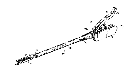
As shown in Fig. 1, a self contained gas powered
endoscopic surgical instrument 50 constructed in accordance
with the principles of this invention includes a frame 52
and an endoscopic portion 54. An anvil 56 and cartridge
assembly 58 are mounted in a distal end 60 of endoscopic
portion 54 and are preferably interchangeable with other
anvil/cartridge assemblies (as discussed in greater detail
hereinbelow) to perform a wide variety of surgical
fastening procedures as needed.
Anvil 56 and cartridge assembly 60 are manually
controlled by means of an articulating handle 62 in the
frame 52. This handle 62 interconnects with anvil 56 by
means of a linkage disposed in endoscopic portion 54 such
that when handle 62 is moved from its open position (Fig.
1) to a closed position (Fig. 7), anvil 56 is moved into
close approximation with cartridge assembly 58. This
operation will be discussed in greater detail below.
Turning now to Fig. 2, an exploded perspective
view of the frame and pneumatic system is shown in
accordance with the present invention. Frame 52 includes a
first housing member 64 and a second housing member 66
enclosing a pneumatic system shown generally at 68.
21 27061
-18-
Articulating handle 62 is pivotally connected at a distal
end thereof to clamp tube 70 at pivot point 72.
Longitudinal grooves 74 formed in both first and second
housing members 64, 66 adjacent pivot point 72 slidably
receive molded shuttles 76 attached to handle 62 at 72.
The molded shuttles 76 are pivotally connected to either
side of the pivot point 72 on the distal end of handle 62
and serve to guide the distal end of handle 62 in a
longitudinally distal direction as the handle is
compressed.
A pair of articulating links 78 interconnect an
intermediate portion of handle 62 to a pair of projections
80 formed on an upper surface of housing members 64, 66
respectively. A handle return spring 82 extends between
handle 62 and housing members 64, 66 by means of spring
anchor pins 84, one of which is disposed in handle 62 and
the other extending between projections 80 which also serve
to pivotally connect articulating links 78 to projections
80. This spring 82 assists in returning handle 62 from its
closed position to its open position.
The proximal end of handle 62 is preferably
diagonally formed away from housing members 64, 66 so as to
enable the surgeon to more easily release the handle 62
from its closed position. This is done by placing the hand
under the proximal end of the handle and lifting. A
texturized or serrated portion 86 may advantageously be
formed on an under surface of the proximal end of handle 62
to enhance gripping of the handle 62.
Pneumatic system 68 is wholly contained within
housing members 64, 66 and includes a container 88 of
relatively low pressure gas longitudinally slidably mounted
therein. The pressure of the gas in container 88 during
212706'x!
-19-
operation of the stapler is typically less than about 200
p.s.i.g. and preferably in the range from about 80 p.s.i.g.
to about 160 p.s.i.g. Any suitable non-toxic gas can be
used including but not limited to halogenated hydrocarbons
which are gaseous at room temperature, e.g., fluorinated
hydrocarbons such as Freon 12 or chlorinated hydrocarbons
such as Freon 152A. Container 88 dispenses the relatively
low pressure gas through stem 90, valve 92 and gas tube 94
when the firing trigger 96 is depressed. Spring 97 is
positioned between container 88 and valve 92 and serves to
hold the container 88 away from valve 92. Valve 92 is
fixed within housing members 64, 66 and is longitudinally
adjustable by means of set screw 93. (Fig. 13) This
feature permits the position of valve 92 to be
longitudinally changed to compensate for manufacturers'
variations in length among containers 88 between a distal
end and the proximal end of stem 90.
Disposed above container 88 within housing
members 64, 66 is a pneumatic actuator 98. Actuator 98
includes a pneumatic cylinder 100 which is held in place by
opposing pins 99 and which is closed at its proximal end
except for ferrule 102 and is open at its distal end, as
well as a pneumatic piston 104 mounted for reciprocal
motion in cylinder 100 parallel to the longitudinal axis of
endoscopic portion 54. Cylinder 100 is preferably circular
in transverse cross-section however other shapes would
function acceptably well.
Piston 104 is pneumatically sealed to cylinder
100 by "0" ring 106 molded of polyethylene or the like.
Gas dispensed from container 88 is supplied to pneumatic
actuator 98 via gas tube 94 which admits the gas to
cylinder 100 through ferrule 102 behind piston 104 to drive
21 27061
-20-
piston 104 distally in the cylinder. The distal end of
piston 104 is adapted to engage the firing mechanism of the
surgical apparatus as will be described in greater detail
below.
Referring to Figs. 2, 5 and 7, firing trigger 96
is pivotally mounted in a proximal end of housing member
64, 66 by pivot pin 108. Spring 110 is positioned adjacent
pin 108 and serves to bias the firing trigger 96 proximally
into the prefiring position. A trigger rod 112 extends
distally from firing trigger 96 longitudinally to engage
piston slide 114 positioned in a lower portion of piston
104. Piston slide 114 comprises a substantially "U"-shaped
channel which fits into a corresponding groove 116 formed
in piston 104. Piston slide 114 is spring loaded in a
proximal direction by spring 118 and includes a transverse
projection 120 on a lower distal end thereof which engages
the distal end of trigger rod 112.
Referring now to Figs. 2 and 5-11 and initially
to Figs. 2, 5-8 and 11, a rocking lever 120 is pivotally
mounted on transverse slide pin 122 and is adapted for
transverse movement relative to slide pin 122 between an
engaged position prior to firing (Figs. 7-9) and a
disengaged position when articulating handle 62 is open
(Figs. 5 and 6). Cam slide 124 is vertically mounted in
first housing member 64 for reciprocal movement between an
upper and lower position (Figs. 6 and 8 respectively) and
serves to move rocking lever 120 between the engaged
position (Fig. 8) and the disengaged position (Fig. 6).
Thus, until the articulating handle 62 is closed causing
cam slide 124 to move rocking lever 120 into the engaged
position, the instrument 50 cannot be fired.
21 2706 1
-21-
Cam slide 124 is normally biased in its upper
disengaged position by cam slide spring 126 mounted in
vertical groove 128 of first housing member 64 (Figs. 5 and
6). In this upper position, cam slide 124 extends upward
beyond first housing member 64 (Fig. 6) to engage
articulating handle 62 as it is moved to a closed position
(Figs. 7 and 8). Cam slide 124 further includes a ramming
surface 130 which contacts a corresponding ramming surface
of ramming block 132 mounted on slide pin 122. Caroming
block 132 is loaded against cam slide 124 by slide spring
134 and moves rocking lever 120 transversely on slide pin
122 between an engaged position and a disengaged position.
Referring to Fig. 8, as the articulating handle 62 is
compressed toward housing members 64, 66 in the direction
of arrow 135 it contacts cam slide 124 moving it downward
and causes ramming surface 130 to move caroming block 132
and rocking lever 120 transversely into an engaged position
in line with piston 104.
Turning to Figs. 5, 7-9 and 11, once the
articulating handle 62 has been fully compressed (Figs. 7-
9) rocking lever 120 is disposed in alignment with piston
slide 114 and can be pivotally moved about transverse slide
pin 122 to engage pusher disk 136 at the distal end of
container 88. When the instrument is in the clamped
configuration, depression of the firing trigger 96 moves
trigger rod 112 distally in the longitudinal direction
causing piston slide 144 to engage and pivot rocking lever
120 which, in turn, engages pusher disk 136 and moves
container 88 longitudinally into contact with valve 92 to
dispense gas and propel piston 104 in the distal direction.
See Figs. 11, 12 and 13.
-22- 2 1 2 7 0 6 1'
As piston 104 moves distally, rocking lever 120
remains in its pivoted firing position by contact with the
bottom surface of piston 104. A gap 138 is formed in the
bottom surface of piston 104 near the proximal end thereof
which gap effectively allows rocking lever 120 to disengage
from piston 104 and pivot back to a position wherein
container 88 is released from engagement with valve 92,
stopping the flow of gas into pneumatic cylinder 100.
Return springs 140, 142 disposed in endoscopic
portion 54 drive piston 104 back to its initial prefired
position. A camming surface 144 is formed in a distal end
of gap 138 and causes rocking lever 120 to move
transversely out of engagement with piston 104 as it
returns proximally and the rocking lever 120 moves to its
original prefired position (Fig. 7).
Fig. 14 shows an alternate embodiment of the
present invention incorporating an adjustment mechanism 146
which permits the instrument 148 to be selectively adjusted
to change the length of the firing and return strokes of
piston 150. This advantageous feature permits the user to
selectively fire a predetermined length of staples using a
single instrument. For example, if the user installs a
staple cartridge assembly having six rows of staples, each
row having a longitudinal length of 60 mm, the instrument
is set using adjustment mechanism 146 to fire the staples
in the entire length of the cartridge. Cartridges having
some lesser length of staples may be inserted and fired
depending on the needs of the user.
The adjustment mechanism 146 shown in Fig. 14
includes a belt 152 which travels around a pair of
longitudinally disposed pulleys 154, 156. A first linkage
rod 158 engages the top portion of belt 152 and extends to
21 27061
-23-
a gap adjustment member 160 slidably positioned in piston
150. A second linkage rod 162 engages the bottom portion of
belt 152 and extends to a slidable piston stop 164 disposed
within pneumatic cylinder 100.
Belt 152 may be rotated in either the clockwise
or counterclockwise direction by rotating knob 166 disposed
in housing 172 between pulleys 154 and 156. This permits
the user to preselect the firing stroke of the instrument
148. For example when belt 152 is rotated counterclockwise,
the firing stroke piston stop is being driven proximally by
second linkage rod 162 and the gap 168 wherein the rocking
lever 120 disengages the pneumatic actuator 98 is
correspondingly widened. This permits the user to fire
shorter rows of staples without changing cartridge
assemblies. Conversely, when belt 152 is rotated in a
clockwise direction, the firing stroke is progressively
lengthened this allowing the user to fire up to the entire
length of the rows of staples in the cartridge assembly.
In the instrument 148 shown in Fig. 14, the
firing stroke may be preset to fire either 30 mm or 60 mm
rows of staples from a 60 mm length cartridge assembly.
These preset positions correspond to camming pins 186 and
170 respectively which serve to disengage first rod linkage
158 from belt 152 so that belt 152 is not rotated during
the firing stroke of the pneumatic actuator 98.
Turning now to Fig. 15, another beneficial
feature is shown incorporated into the pneumatic system in
accordance with the present invention. This feature
comprises a pressure sensor 174 disposed in line between
the valve 92 and the pneumatic cylinder 100 to sense and/or
regulate the gas delivered from container 88 to the
cylinder 100. During surgical procedures involving the
-24- ; 212706'x'
driving of surgical fasteners and particularly where a
knife is used to divide fastened tissue, it is important
that when the trigger is depressed there is sufficient gas
remaining in the container 88 to complete an entire piston
firing stroke. If insufficient gas were available, the
piston may not be able to fasten and/or divide the desired
length of tissue, necessitating duplication of the
procedure. Pressure sensor 174 serves to premeasure the
amount of gas necessary to achieve the desired piston
stroke before activating to permit the gas to flow into the
pneumatic cylinder 100 to drive piston 104.
It is also envisaged that a counter mechanism can
be incorporated to operate in conjunction with the
pneumatic system 68 in order to monitor the number of
firings which the instrument has been subjected to. This
number can be visually displayed to the operator so that,
for example, after a given number of firings, the
instrument can be overhauled or replaced. Similarly, where
a relatively small number of firings are available from a
single gas container, this counter mechanism will assist
the operator in recognizing when the container is nearing
exhaustion. In a particularly desirable embodiment, the
counter mechanism can be combined with a lockout mechanism
which will disable the firing mechanism after a preselected
number of firings.
As seen in Fig. 15, upon depressing firing
trigger 96, gas is released from container 88 substantially
as described hereinabove. However, after leaving stem 90
and passing through nozzle 92, the gas contacts pressure
plate 176. Pressure plate 176 is preset by means of spring
178 to keep orifice 180 closed until a predetermined gas
pressure is realized at the pressure plate 176. Once this
M _2127061
-25-
threshold pressure is realized, pressure plate 176 moves
out of contact with orifice 180 permitting gas to pass
therethrough and into pneumatic cylinder 100 to drive
piston 104 distally. In the event that insufficient gas is
available to reach this threshold pressure, pressure plate
176 continues to block orifice 180 and the instrument
cannot be fired.
Referring now to Fig. 3, there is shown in
exploded detail an endoscopic portion 54 in accordance with
one embodiment of the present invention. At a proximal
end, piston 104 is longitudinally reciprocally slidable
through clamp tube 70 and extends into the proximal end of
cover tube 182. The distal end of piston 104 is provided
with an attachment flange 184 which flange 184 mounts a
plurality of pusher washers 186 thereon. These pusher
washers 186 are formed in a substantially abbreviated
frustoconical cross-section from a resilient material such
as, for example, commercial spring steel or type 302
stainless steel. These washers are typically known as
Belleville Spring Washers available through SPEC Associated
Spring Raymond, Barnes Group Inc. The washers are
especially suited for high loads in small spaces and may be
combined in varying sequences to achieve numerous load
carrying possibilities. In the embodiment of Fig. 3, a
total of twelve pusher washers are used substantially as
shown in Fig. 3A with duplicate washers arranged in six
opposing sets. A spring support washer 188 is positioned
on flange 184 distal to pusher washers 186 and serves to
engage the proximal ends of inner and outer return springs
140 and 142. Lock washer 189 holds the washers in place on
flange 184.
(2127061
-26-
Attachment flange 184 has a chamfered distal tip and is
configured and dimensioned to be received between the
proximal fingers 190 and channel 192.
As shown in Figs. 3 and 16-18, channel 192 is an
elongated structure slidably mounted in endoscopic portion
54 for reciprocal longitudinal motion therein. As
mentioned above, channel 192 has fingers 190 at a proximal
end thereof to receive attachment flange 184 of piston 104.
At a distal end of channel 192 there is provided a fork 194
defining a slot 196 therebetween. Fork 194 has a pair of
opposed ramping surfaces, 198 and 200 respectively, the
purposes of which will be described in greater detail
below. Proximal to fork 194 is abutting structure 202
which structure extends below the lowermost dimension of
fork 194.
Referring back to Fig. 3, an extension sleeve 204
is disposed within the cover tube 182 and is fixed on a
proximal end thereof to clamp tube 70. Sealing member 206
is mounted on flange 208 of clamp tube 70 and serves to
sealably isolate the frame 52 of the instrument 50 from the
endoscopic portion 54. Inner and outer return springs, 142
and 140 respectively, are contained within upper extension
spacer 210 and lower extension spacer 212 which are, in
turn, fixed within the extension sleeve 204. Spring
support washer 188 abuts the proximal ends of inner and
outer return springs 142 and 140 and, when the instrument
is fired, transmits the energy of the compressed springs
142, 140 to the piston 104, returning it to its prefired
position.
Support structure 214 is also disposed within
extension spacers 210, 212 and function to releasably
receive anvil and/or cartridge assemblies in instrument 50.
.._ _27_ a 2 1 2 7 0 6 1
Support structure 214 is retained in place within extension
spacers 210, 212 by transverse support key 216. An anvil
return spring 218 is affixed to an underside portion of
support structure 214 and assists in the retention of the
anvil within the instrument.
A collar assembly, shown generally at 220, is
attached to the respective distal ends of external sleeve
204 and extension spacers 210, 212. This assembly 220
includes a forward collar tube 222, a collar tube spacer
224 and a rear collar tube 226, each having camming bosses
268, 270 formed on inner surfaces therein as will be
described in greater detail below.
In the embodiment of the present invention shown
in Figs. 1-3, the endoscopic portion 54 is rotatable
relative to the frame 52 by means of rotation knob 228
(Figs. 1 and 2). This rotation knob 228 is in the form of
an abbreviated frustoconical structure having a bore
therethrough dimensioned to receive a proximal end of cover
tube 182. At a proximal end of knob 228, knurling.229 may
be provided to facilitate rotation. Once connected to
cover tube 182, rotation of knob 228 causes the distal
working end of the instrument to rotate.
Referring now to Figs. 4 and 19-27, there is
illustrated an anvil 230 and cartridge assembly, shown
generally at 232, in accordance with one embodiment of the
present invention. Anvil 230 is an elongated piece which
is mounted in support 214 by means of proximal legs 250.
At its distal end, anvil 230 has an anvil plate 236 with a
tissue contacting surface 238 having staple forming
depressions 240 (See Fig. 19). At its proximal end, anvil
230 is provided with an upper camming surface 242 and
locking surface 244, which surfaces are engagable with
2~ ~706'tl
-28-
corresponding top arcuate ramming surface 246 formed in
forward collar tube 222. Transverse opposing projections
248 are formed on legs 250 at the proximal end of anvil 230
and provide an engagement point for anvil 230 to be rammed
between an open and closed position by the interaction of
ramming surface 242, locking surface 244 and top arcuate
caroming surface 246 of collar tube 222. Preferably, the
radius of curvature of the top arcuate ramming surface 246
is shorter than the radius of curvature of ramming surface
242 and equal to the radius of curvature of locking surface
244. This configuration prevents flexing of the caroming
surface 246 of collar tube 222 and lateral movement of the
anvil as it is being rammed closed.
Anvil plate 230 also has a longitudinal center
groove 252 to permit passage of a knife 254. Anvil 230 is
further provided with parallel aligning surfaces 256
positioned below caroming surface 242. These aligning
surfaces are dimensioned to fit outside projections 258 on
cartridge housing 260 upon closure of the anvil 230. The
engagement of the aligning surfaces 256 and the
corresponding projections 258 of cartridge housing 260
serves to more accurately and securely align anvil 230 and
cartridge housing 260 upon closure. Further visual
confirmation of alignment is facilitated by a pair of
parallel longitudinal indentations 262 formed in the distal
end of anvil 230. These indentations 262 allow the surgeon
to view the closed structure of the anvil 230 and cartridge
assembly 232 to confirm accurate longitudinal alignment
thereof.
Further, as shown in Fig. 21, the horizontal
plane formed by tissue contacting surface 238 intersects
the horizontal plane formed by the ramming portion of the
21 2706'
-29-
proximal end of anvil 230 at an obtuse angle "a". This
angular orientation pre-cambers the anvil 230 and balances
the closure force applied by the anvil 230 to the captured
tissue.
First and second caroming surfaces, 264 and 266
respectively, are formed in a sidewall portion of the
proximal end of anvil 230. These caroming surfaces engage
caroming bosses, 268 and 270 respectively, formed on inner
opposing sidewalls of collar tube assembly 220. Anvil 230
is inserted into collar tube assembly 220 and projections
248 engage with support structure 214 bring caroming
surfaces 264 and 266 into engagable alignment with caroming
bosses.268 and 270. Cartridge assembly 232, discussed in
greater detail hereinbelow, is fixedly inserted into collar
tube assembly 220 and remains stationary relative to anvil
230.
During fabrication of anvil 230, the anvil blank
may advantageously be formed by metal injection molding and
thereafter coined and coated as described below. A wide
variety of staples and fasteners are contemplated for use
with the present apparatus. In a preferred embodiment for
use with titanium fasteners, it has been found that forming
of the fasteners in the staple forming depressions 240 is
facilitated by applying a hard, relatively smooth surface
on the staple forming portion of the anvil 230. The
preferred method of application of this surface is by
electroless plating, with the surface being formed of a
metallic alloy such as, for example, nickel, gold, silver,
titanium nitride or chromium. Where nickel is used, the
applied surface is preferably in the range of 100 ~ -2000
~,in thickness with an optimum thickness of between 200 ~c -
2 ~ Z~os t~
-30-
500 u. Ranges for other alloy may vary depending upon
their inherent characteristics.
Where nickel is to be applied, the preferred
method is an electroless plating method including the steps
of: electrocleaning the anvil in a cyanide-containing
cleaner, reversing polarity at predetermined intervals,
preferably about every 10-15 seconds, at a current of about
50 amps/ft2; rinsing thoroughly; rinsing in a solution
containing a strong acid, preferably 20% HCL, dipping
several times; immersing the anvil in a NiCL strike tank
for plating, preferably for two to four minutes at a
current of about 50 amps/ft2; rinsing; and immersing the
anvil in an electroless Ni bath, preferably Enthone 418 or
431, for a time sufficient to achieve the desired plating
thickness. For example, at a deposition rate of .0005
in/hr, a time of between 30 to 40 minutes would be required
to achieve a thickness of about 300 ~, + 50 ~. Other
coating procedures are also contemplated including vapor
deposition, etc. and are encompassed by the present
invention.
Turning now to Figs. 4 and 22-27, there is
illustrated a replaceable cartridge assembly 232 in
accordance with the present invention. The cartridge
assembly 232 includes: a cartridge housing 260; a
cartridge 272 having a plurality of pushers 274 and staples
276 disposed in longitudinal arrangement therein; and a
plurality of cam bars 278 removably disposed in cam bar
adapter 280 and a cam bar alignment tab 282 as well as a
knife 254 mounted in the cam bar adapter 280.
Referring specifically to Figs. 25-27, the
proximal end of cartridge housing 260 comprises a
substantially elongate channel of semi-circular cross-
. 21 27061
-31-
section having a forward and rearward portion 284 and 286
respectively. A transverse locking slot 288 is formed in
rearward portion 286 and serves to engage and retain
support structure 214. Upon insertion into collar tube
assembly, the forward end of support structure 214 is
biased by the rearward portion 286 of cartridge housing 260
until the support structure 214 engages locking slot 288.
Rearward projection 290 is formed in the base of
cartridge housing 260. The function of this projection 290
will be described in greater detail below. Forward of the
projection 290 is a bore 292 which receives shear pin 294
formed on cam bar adapter 280 (Figs. 22-24). A pair of
crimps 296 is provided in opposing sidewalls of the
rearward portion of the proximal end of the cartridge
housing. These crimps 296 provide a friction fit with cam
bar adapter 280.
The forward portion 284 of the proximal end of
cartridge housing 260 has projections 258 which, upon
closure of the cartridge assembly 232 and anvil 230,
contact and align with anvil aligning surfaces 256 as
described above.
The distal end of the cartridge housing 260
comprises a channel structure of substantially rectangular
cross-section. This distal end constitutes the cartridge
receiving portion and is dimensioned to receive cartridge
272 therein. Bores 298 and projection 300 serve to engage
pins and bores respective in the cartridge 272 so as to
align and retain the cartridge 272 within the cartridge
receiving portion of the cartridge housing 260.
Referring to Fig. 26, the cartridge receiving
portion in the distal end of cartridge housing 260 and the
proximal end of cartridge housing 260 are joined at an
21 27~61
-32-
obtuse angle a defined by the intersection of the
horizontal planes of both the proximal and distal ends of
the cartridge housing 260. This angular orientation serves
to pre-camber the cartridge assembly and facilitates
accurate closure and alignment of the jaw elements as well
as more secure retention of subject tissue.
The cartridge 272 includes longitudinal groove
structure 302 for receiving and guiding knife 254 and a
plurality of pushers 274 abutting staples 276. The staples
276 are advantageously arranged in six longitudinal rows
with three rows positioned on either side of groove
structure 302.
Two pairs of longitudinal slots are formed in the
cartridge housing 260 and are adapted to receive a pair of
double cam bars 278 therein. Each pair of cam bars serving
to drive three corresponding longitudinal rows of staples.
Further, the two pairs of longitudinal slots extend to the
end of cartridge 232.
Cam bars 278 are provided with a cam surface 304
in an upper distal end thereof and an overhanging ledge 306
with vertical surface 308 in a lower distal end. This
overhanging ledge 306 is dimensioned to extend into the
longitudinal slots to a point wherein the vertical surface
308 of the overhanging ledge 306 drops down and abuts the
forward edge 310 of the cartridge retaining portion of the
cartridge housing 260 when the cam bars 278 move to their
distal fired position. At their proximal end, cam bars 278
are provided with hook structure 312 for releasably
engaging cam bar adapter 280.
Referring now to Figs. 22-24, there is shown
multiple views of the cam bar adapter 280 in accordance
with one embodiment of the present invention. The cam bar
21 2706 1
-33-
adapter 280 comprises a forward section 314 and a rearward
section 316. The forward section 314 is substantially
rectangular in shape and has a central longitudinal groove
318 formed therein and dimensioned to receive the
longitudinal groove structure 302 therein when the cam bar
adapter is urged to its forwardmost position. Flanges 320
and shelves 322 serve to removably retain the proximal end
of cam bars 278.
The rearward section 316 is rectangular in shape
with projections 324 formed in the proximal end thereof.
The rearward section is dimensioned to be receivable within
the slot formed in fork 194 in channel 192. The
projections 324 are dimensioned to engage ramping surface
198 to allow the fork 194 to ride up and over the
projections 324 when the fork 194 is moved in the distal
direction.
Vertical bore 326 and longitudinal groove 328 are
formed in the rearward section 316 and serve to retain and
hold the shank of knife 254. Shear pin 294 is integrally
formed with cam bar adapter 280 on a bottom surface thereof
and, in the prefiring position, is aligned with and
receivable into bore 292. Also, in this prefiring
position, the rearward section 316 of the cam bar adapter
280 is disposed over rearward projection 290 to effectively
shield engagement of abutting structure 202 with projection
290.
Turning now to Figs. 28-34, there is shown a
second preferred embodiment of an anvil and cartridge
assembly in accordance with the present invention.
Referring to Figs. 28 and 29, the cartridge assembly 330
comprises a cartridge housing 332 mounting a cartridge 334
containing a plurality of pushers 336 disposed beneath
_2127061'
-34-
staples 338, in a distal end thereof. A pair of cam bars
340 are positioned in the cartridge housing 332 and are
adapted to move longitudinally through parallel
longitudinal slots formed in cartridge 334. A caroming
surface 342 is formed on an upper distal end of cam bars
340 with an overhanging ledge 344 formed on a lower distal
end. Vertical ledge 346 is formed proximal to overhanging
ledge 344 and is adapted to engage the distal end of
cartridge housing 332 when the cam bars 340 are driven to
their full distal position. A cam bar alignment tab 348
engages both cam bars 340 and holds them in parallel
alignment. A cam bar adapter 350 is adapted to fixedly
receive the shank portion of cam bars 340.
Cartridge 334 is designed with three longitudinal
rows of staples with each row of staples being offset from
adjacent rows as shown in Fig. 28. This embodiment of the
present invention does not utilize a knife structure and is
designed to place rows of staples in body tissue.
Accordingly, it is not necessary for the cam bars 340 to be
retracted by channel 192. Thus, in operation, the distal
end of channel 192 engages the proximal end of cam bar
adapter 350 and drives cam bars 340 to their extreme distal
position (Fig. 34). In that position, overhanging ledges
344 drop over the distal end of cartridge housing 332 and
remain there. As the piston 104 retracts, channel 192
moves away from cam bar adapter 350 and retracts to a
position proximal to rearward projection 290, leaving cam
bars 340 and cam bar retainer 350 in the distal position
within cartridge assembly 332.
Referring to Figs. 30-31, an anvil 352 is shown
having substantially the same design as anvil 230 described
hereinabove with respect to the previous embodiment. The
2 ~ 2~os ~
-35- '
primary difference is that the distal portion 354 of anvil
352 is narrowed to receive and form three longitudinal rows
of staples in contrast to the six rows of staples and knife
accommodated by anvil 230. Anvil 352 includes a pair of
longitudinally extending parallel legs 356 having
transverse opposing projections 358. Parallel aligning
surfaces 360 are formed in sidewalls of anvil 352 and serve
to overfit and align anvil 352 on cartridge housing 332.
First and second ramming surfaces 362, 364 are formed in
sidewalls of anvil 352 proximal to parallel aligning
surfaces 360 and serve to engage ramming bosses 268, 270
formed in forward collar tube 222 and rear collar tube 224,
respectively.
Upper caroming surface 366 is formed on an upper
surface of anvil 352 proximal to distal end 354 with
locking surface 368 formed distally adjacent upper ramming
surface 366. Both the upper ramming surface 366 and the
locking surface 368 are adapted to engage and be rammed by
top arcuate ramming surface 246 formed in the distal end of
forward collar tube 222.
Figs. 35-39 show a further embodiment of the
present invention similar to that shown in Figs. 1-15 with
the jaw structure of Figs. 28-34. Referring to Figs. 35-36,
the handle portion of this embodiment further includes
annular seals 101, 103 provided between the distal end of
frame 52 and the proximal end of cover tube 182. These
seals serve to further inhibit the escape of insufflation
gas from the operative site. Seals 107 and 109 are
positioned adjacent the proximal and distal ends,
respectively, of clamp tube 70 to better seal off
insufflation gas from the area of the piston 104.
2127061
-36-
A counter mechanism is also disposed in handle
portion 52 and comprises a counter ratchet 400 attached to
trigger rod 112 and a leaf spring 402 mounted in housing 66
so as to engage the teeth on the bottom surface of counter
ratchet 400. Numerical indicators are longitudinally
disposed on an outer surface of the counter ratchet 400 and
correspond to the number of times the instrument has been
fired. An access plate 404 having a viewing window 406
therein is positioned in the outside surface of housing 66.
In operation, each time the instrument is fired
the leaf spring 402 engages a respective proximally located
tooth of the counter ratchet 400, effectively sliding the
counter ratchet 400 distally to align the next lower number
in viewing window 406. The counter mechanism of this
embodiment further includes a locking feature whereby the
trigger button 96 is retained in the fired position when
the leaf spring 402 engages the most proximal surface of
the counter ratchet 400 and prevents the firing rod 112
from returning to its proximal unfired position.
This embodiment of the present invention further
includes an integral trigger button rotary safety mechanism
comprising a rotary safety shaft 408 disposed within a
roller 410. The rotary safety mechanism is rotatably
positioned in trigger button 96 with the roller 410
extending out beyond the plane of the back surface of
trigger button 96. Projections 412 are eccentrically formed
on both sides of rotary safety shaft 408 and extend out
beyond the plane of the side surfaces of the trigger button
96. Spring 414 serves to normally bias the rotary safety
mechanism with the projections 412 disposed in their
distalmost orientation.
21 270fi 1
-37-
Referring now to Figs. 38 and 39, in the
instrument's unfired position (Fig. 38) projections 412 are
in their distalmost position and are disposed in direct
alignment with the proximal ends of the housing members 64,
66. In this position, the trigger button 96 cannot be
accidentally depressed to fire the instrument. In order to
disengage the safety mechanism, the roller 410 is moved in
the direction of arrow 416 which serves to rotate
projections 412 from their distalmost position (Fig. 38) to
their proximalmost position (Fig. 39) effectively allowing
trigger button 96 to be depressed to fire the instrument.
As soon as roller 410 is released, spring 414 returns the
safety mechanism to its normal position to prevent
subsequent accidental firings.
Fig. 37 shows the endoscopic portion and the jaw
portion of the surgical apparatus of Fig. 35. The anvil
418 of this embodiment is provided with a pair of angled
proximal legs 420. This feature permits the anvil 418 to
be opened wider to more easily receive tissue between the
anvil 418 and cartridge 58. The angled proximal legs 420
preferably extend at an angle of between 0 and 30° from the
longitudinal plane of the anvil.
A clamp lockout structure is shown in detail in
Figs. 37, 40 and 41 incorporated into the support structure
214 and upper extension spacer 210. The clamp lockout
structure comprises a leaf spring 430 having a diagonally
downwardly extending projection 432 attached thereto. A
slot 434 is formed through the top surface of support
structure 214 and is adapted to engage and receive
projection 432 whenever the support structure is not
longitudinally aligned. This clamp lockout structure is
designed and configured to prevent the instrument jaws from
-38- 2127061
closing on tissue unless the cartridge and/or jaw elements
are properly emplaced within the apparatus.
In operation in the stapling apparatus of Fig.
37, leaf spring 430 and projection 432 are normally
disposed above support structure 214. The proximal ends of
the cartridge 334 and the anvil 418 are inserted through
collar tube 222 and brought into engagement with the distal
end of support structure 214. (See Fig. 40) In the event
that the cartridge 334 and/or the anvil 418 are not
properly and/or completely inserted into engagement with
support structure 214, the resulting angular disposition of
the support structure 214 brings slot 434 into alignment
with projection 432. (See Fig. 41) As the operator
attempts to depress the handle 62, the extension spacer 210
begins to move distally causing projection 432 to enter
slot 434 and become entrapped therein effectively
preventing any further distal movement of the extension
spacer 210 and, in turn, preventing approximation of the
anvil 418 and the cartridge 334.
In use, the endoscopic portion of the instrument
is inserted into the body, preferably through an endoscopic
tube. It is further preferred that the endoscopic tube
apparatus be capable of maintaining a sealed
pneumoperitoneum, with the internal sealing member of the
housing further maintaining this seal despite introduction
of the instrument in accordance with the invention into the
endoscopic tube. As a practical matter, the jaws of the
instrument are closed for insertion into the endoscopic
tube, either by pinching the anvil and cartridge prior to
insertion or by closing the articulating handle to cam the
jaws closed prior to insertion.
2 1 2706 ~'
-39-
After insertion into the endoscopic tube, the
endoscopic portion may be rotated in order to appropriately
orient the instrument at the stapling site. Rotation of the
endoscopic portion relative to the body may be attained by
rotating the instrument, as a whole, by rotating the
endoscopic portion relative to the frame using rotation
knob 228 (See Fig. 1), or by a combination thereof.
Referring to Figs. 3, 5-8 and 32-34, with the
instrument properly oriented so that the tissue to be
fastened is disposed between the open jaws of the
instrument, i.e., between the tissue contacting surfaces of
anvil member 230 and cartridge 302, the jaws are closed to
clamp the tissue. In the first embodiment, the surgeon
presses down on actuating handle 62, thereby sliding collar
tube assembly 220 distally, via clamp tube 70, extension
sleeve 204, and extension spacers 210, 212.
Referring to Figs. 32-34, as collar tube assembly
220 moves distally in the direction of arrow A from a first
position where the top arcuate caroming surface 246 at the
distal end of forward collar tube 222 is proximal to
caroming surface 242, (Figs. 32-33), to a second position
where the top arcuate caroming surface 246 is engaged with
locking surface 244, (Fig.34), the top arcuate caroming
surface 246 contacts the caroming surface of the anvil,
thereby forcing the anvil to cam via caroming surfaces 264,
266 on caroming bosses 268, 270 until the anvil is brought
into close cooperative alignment with the cartridge
assembly. Fig. 34 illustrates the instrument with the jaws
in a closed position.
After closing the instrument jaws, the instrument
is ready to be fired. When the surgeon is ready to emplace
the staples and cut tissue, firing trigger 96 is depressed
21 27061
-40-
to actuate the pneumatic actuator 98 as discussed in detail
above. Piston 104, attached to the proximal end of channel
192 is driven distally causing caroming surface of forks 194
to ride up and over projection 324 of the cam bar adapter
280 and drive the cam bar adapter in a distal direction.
Shear pin 294 is severed and the cam bars and knife are
driven longitudinally through the cartridge to sequentially
drive and form staples and cut tissue.
As piston 104 contacts return springs 140, 142,
pusher washers 186 are compressed on themselves and serve
to store energy as the piston moves distally toward the
cartridge assembly. This initial compression occurs in the
range of between about 20 p.s.i. to about 150 p.s.i. and
preferably within a range of about 30 p.s.i, to about 60
p.s.i. Near the end of the distal stroke of the piston
104, this stored energy is released to drive the cam bars
278 through the final distal limits of their travel within
the longitudinal slots in the cartridge. At the distal
extreme of the longitudinal stroke, the overhanging ledges
306 of cam bars 278 drop over the edge of the cartridge
housing thus abutting vertical surface 308 with edge 310.
After firing, return springs 140, 142 engage
piston 104 and return it to its original position. The
return motion of piston 104 causes rocking lever 120 to be
caromed aside by caroming surface 144 of piston 104. In the
embodiment containing knife 254 discussed above, the cam
bars 278 are pulled out of cam bar adapter 280 and remain
in position in the longitudinal slots of the cartridge 334.
The cam bar adapter, with knife 254 attached, moves
proximally within cartridge housing 272 until the outer
edges of cam bar adapter 280 impinge on crimps 296.
__ 21 27p6 ~,
-41- _
The cam bar adapter 280 is held in place by
crimps 296 while camming surface 200 of fork 194 causes the
fork to ride up and disengage with projection 324 of the
cam bar adapter. Channel 192 continues to move in the
proximal direction until abutting structure 202 is
positioned proximally to rearward projection 290 formed in
the floor of cartridge housing 260. At this point, the
entire cartridge assembly 232 is deactivated.
In the event that the surgeon should accidentally
attempt to again fire the instrument without replacing the
deactivated cartridge with a new unfired cartridge, the
resulting distal longitudinal motion of the channel 192
moves abutting structure 202 into contact with rearward
projection 290 effectively preventing further movement of
forks 194 toward cam bar adapter 280.
After firing, articulating handle 62 is raised
with the assistance of handle return spring 82 which action
retracts collar tube assembly 220. This retraction causes
anvil 230 to cam out of engagement with cartridge assembly
232. Similarly, raising of articulating handle 62 causes
cam slide 124 to move upward disengaging the pneumatic
firing mechanism.
In order to replace the cartridge assembly, the
instrument is withdrawn from the patient. The cartridge
assembly is released and may be removed by pulling it
distally out of collar tube assembly 222. To reinsert a
new cartridge assembly, the proximal end of the cartridge
assembly is inserted into collar tube assembly 222 until
engaging and locking into support structure 214. The
instrument is now ready for reinsertion and continued use.
Turning to Figs. 42-48, there is illustrated a
mechanism for inhibiting the premature discharge of low
_2127p6~
-42-
pressure gas from container 88 into valve 92 during
shipment of the surgical apparatus 50, which comprises a
blocking bar designated generally by reference numeral 400.
Specifically, blocking bar 400 functions to inhibit the
relative approximation of container 88 and valve 92, and in
particular to inhibit movement of container 88 toward valve
92. Blocking bar 400 is mounted in the frame 52 of surgical
instrument 50 and is movable between a shipping position,
which is shown in Figs. 43, 45 and 46, wherein container 88
is inhibited from moving toward the valve 92, and an
operating position, shown in Figs. 44 and 47, wherein the
container 88 is permitted to move toward the valve 92 to
actuate the instrument.
Referring again to Fig. 42, blocking bar 400
includes: a cylindrical button portion 402 dimensioned to
extend through a porthole 404 formed in the wall of housing
portion 64 when blocking bar 400 in the shipping position
(see Fig. 43); a recessed region 406 for accommodating
movement of the container 88 when the blocking bar 400 is
in the operating position; a blocking region 408
dimensioned to contact or abut the proximal end of
container 88 when the blocking bar 400 is in the shipping
position; and a biased, cantilevered clasp 410, best seen
in Fig. 46, which is configured to engage a ridge 412
formed on the interior wall 65 of housing portion 66 when
the blocking bar 400 is in the shipping position. Ridge
412, in conjunction with spaced apart buttresses 414,
define a portion of the chamber within which container 88
is accommodated in handle 52. The buttresses 414 are
contoured in such a manner so as to provide a smooth seat
for container 88. In order to further provide a smooth
unobstructed pathway for the container 88 to travel within
2 ~ zaos 1!
-43-
when the pneumatic assembly is actuated, the surfaces of
the recessed region 406 are contoured in substantially the
same manner as buttresses 414.
In use, upon removal of the surgical apparatus 50
from a shipping package, the user may depress the
cylindrical button portion 402, urging the blocking bar 400
out of the shipping position of Fig. 46 by deflectably
disengaging the clasp 410 from ridge 412. The
disengagement of clasp 410 is primarily achieved by
overcoming the bias normally imparted thereby. Once the
blocking bar 400 has been moved into the operating position
of Fig. 47, the container 88 will be permitted to move
toward the valve 92 such that valve stem 90 is engagable
therewith.
Turning to Figs. 49-51, there is illustrated
another embodiment of a cartridge assembly constructed in
accordance with a preferred embodiment of the subject
invention which is designated generally by reference
numeral 500. Cartridge assembly 500 is particularly
configured to inhibit exposure of the cutting edge 502 of
knife 504 following a staple driving/tissue cutting
operation. Specifically, the cartridge assembly 500
includes a mechanism for moving the cutting edge 502 of
knife 504 out of intersection with the tissue contacting
surface 506 of cartridge 510. To achieve this advantageous
result, the distal portion of cartridge 510 is formed with
a retaining chamber 512 for enclosing knife 504. Retaining
chamber 514 is defined by an angled caroming wall 516 having
an angle of inclination directed distally and configured to
cooperate with the angle of inclination of the cam surface
518 of the cam bar assembly 520 upon which knife 504 is
mounted.
44
In operation, the cam bar assembly 520 is driven
through the cartridge 510 from the prefired position of
Fig. 49, to the fired position of Fig. 50. As the cam bar
assembly 520 traverses cartridge 510, knife 504 intersects
the tissue contacting surface 506 to incise tissue. When
the cam bar assembly approaches the distal end of cartridge
510, as illustrated in Fig. 50, the camming surface 518 of
cam bar assembly 520 contacts the camming wall 516 of
retaining chamber 512, causing the cam bar assembly 520 to
move into the retaining chamber 512. Continued distal
movement of the cam bar assembly 520, under the influence
of the actuation system of surgical apparatus 50, will urge
the cam bar assembly 520 further into retaining chamber
512, until the cutting edge 502 of knife 504 is moved out
of intersection with the tissue contacting surface 506 of
cartridge 510. At such a time, the knife 504 will no
longer be exposed, and contact therewith will be inhibited.
Referring to Figs. 52-55, another embodiment of a
cartridge assembly constructed in accordance with a
preferred embodiment of the subject invention is
illustrated and is designated generally by reference
numeral 550. Cartridge assembly 550 is also provided with
a mechanism for inhibiting exposure of the cutting edge 502
of knife 504. This mechanism includes a spring biased
retaining member 552 positioned within a retention cavity
554 defined in the distal portion of cartridge 560.
Retaining member 552 is defined by an anchoring
leg 562 which includes an engaging tab 564 for securing the
retaining member 552 in cavity 554, and a camming leg 566
which is configured to cooperate with the camming surface
518 of cam bar assembly 520 for moving the cam bar assembly
into cavity 554. The engaging tab 564 of anchoring leg 562
-z~z~OS~r
-45-
is impinged against a shelf 565 defined in cavity 554. The
caroming leg 566 of retaining member 552 is normally
maintained in an operative position by a support boss 568
which depends from the side wall 570 of cartridge 560. In
this position, caroming leg 566 will engage the caroming
surface 518 of cam bar assembly 520 as it approaches the
distal end of cartridge 560 under the influence of the
actuation system of instrument 50 during which time the
cutting edge 502 of knife 504 intersects the tissue contact
surface 506 of cartridge 560.
In use, initial interaction between the caroming
leg 566 of retaining member 552 and the caroming surface 518
of cam bar assembly 520, will lift the caroming leg 566 off
the support boss 568, as illustrated in Figs. 53 and 54.
Then, as the cam bar assembly 520 continues to translate in
a distal direction and the proximal edge 520a thereof
clears the distal edge 560a of the staple support region
560b of cartridge 560, the caroming leg 566 will force the
cam bar assembly 520 into the retaining cavity 554 moving
the cutting edge 502 of knife 504 out of intersection with
the tissue contacting surface 570 of cartridge 560, as
shown in Fig. 54, thereby inhibiting contact with the
cutting edge 502.
Referring to Fig. 56, another embodiment of a
cartridge housing constructed in accordance with a
preferred embodiment of the subject invention is
illustrated and is designated generally by reference
numeral 600. Cartridge housing 600 is provided with a pair
of independently mounted pivoting tissue engaging arms 602
and 604 which are particularly configured to fractionally
engage tissue that has been positioned adjacent the tissue
contacting surface 272a of cartridge 272, to inhibit
2127p6 ~
-46-
movement of the tissue, particularly during an end-to-end
anastomosis procedure in which two tubular vessels are
joined to one another. The tissue engaging arms 602 and
604 are each formed with a pair of spaced apart atraumatic
fingers, 602a and 602b, and 604a and 604b, respectively.
The fingers are particularly adapted to fractionally engage
tissue without causing trauma or damage thereto.
Engaging arms 602 and 604 are pivotably mounted
to the opposed side walls 606 and 608 of cartridge housing
600 by pivot pins 610 and 612, respectively. Tabs 614 and
616 are provided on engaging arms 602 and 604,
respectively, for facilitating the manipulation thereof.
Each of the tabs 614 and 616 are formed with a pair of
outwardly extending pegs 624a and 624b, and 626a and 626b,
respectively, for interacting with the housing 600 to
control the movement of engaging arms 602 and 604.
Specifically, as illustrated in Figs. 57 and 58, peg 624a
cooperates with a circular guide port 630 which is defined
in the side wall 606 of housing 600. Guide port 630
functions to limit the rotational travel of engaging arm
602 as it is moved between the tissue engaging position of
Fig. 57, and the disengaged position of Fig. 58. Peg 624b
interacts with a pair of spaced apart retention notches 632
and 634 which are defined in the side wall 606 for
receiving and releasably retaining peg 624b when the
engaging arm 602 is positioned in the tissue engaging
position of Fig. 57 and the disengaged position of Fig. 58
(corresponding retention notches, not shown in the figures,
are also provided in side wall 608 of cartridge housing 600
for interacting with peg 624b of engaging arm 604). In
use, prior to introducing the surgical instrument of the
subject invention into the surgical site, the user may move
2127p6 ~
-47-
the tissue engaging arms 602 and 604 into a tissue engaging
position to inhibit movement of the target tissue to be
stapled. Alternatively, if tissue engaging arms 602 and
604 are not needed during a particular stapling procedure,
they may remain in a disengaged position so as not to
interfere with the target tissue.
It will be understood that various modifications
can be made to the various embodiments of the present
invention herein disclosed without departing from the
spirit and scope thereof. For example, various sizes of
the instrument are contemplated, as well as various types
of construction materials. Also, various modifications may
be made in the configuration of the parts. For example, in
the first embodiment the elongated slot for allowing access
to the thumbwheel may be placed alternatively in the left
body portion or right body portion. Therefore, the above
description should not be construed as imitating the
invention but merely as exemplifications of preferred
embodiments thereof. Those skilled in the art will
envision other modifications within the scope and spirit of
the present invention as defined by the claims appended
hereto.