Note: Descriptions are shown in the official language in which they were submitted.
~ METHOD FOR CONTROLLING TRANSMISSION CONTROL CLUTCHES
Background of the Invention
This application includes a microfiche appendix including
6 microfiche and 249 frames.
This invention relates to a vehicle transmission control
system, in particular a microprocessor-based electronic
control system for a powershift transmission having hydraulic
pressure operated transmission control elements, such as
brakes and clutches, and solenoid operated valves for
controlling the hydraulic pressure delivered to the control
elements, and more particularly to a system and method for
controlling the electrical signals applied to the solenoid
operated valves.
Some manufacturers have used versions of electrohydraulic
transmission controls with some success. For example, a
powershift transmission sold by Ford New Holland, Ltd. has two
modulating valves which control three different transmission
control clutches. These valves are in turn controlled by an
electronic controller. Such a proportional control allows a
clutch element to be modulated during engagement and release
of that element, and the controller provides the ability to
vary the modulation for a particular element for each unique
shift. Another system which includes on-off valves and at
least one proportional control valve is described in US patent
No. 4,855,913, issued 8 Aug. 1989 to Brekkestran et al.
In such systems each clutch may have a different fill
volume and thus may require different fill times. US Patent
No. 5,082,097, issued on 21 January 1992 to Goeckner et al.
relates to a tr~n.q~ sion controller for a transmission which
includes a solenoid valve operated clutch and a solenoid valve
for operating the clutch. The Goeckner et al. system also
discloses a calibrating system or a system for determining a
current signal corresponding to the point at which the clutch
begins to transmit torque. U.S. Patent No. 5,224,577,
discloses methods for determining a fill pressure calibration
value and a fill volume calibration value.
It would be desirable to control the timing of subsequent
pressurization of such a clutch (after it is filled) with
respect to the end of the time period required to fill the
clutch. If this is done, and if the fill time is adjusted to
compensate for various conditions, then the timing of
subsequent pressurization of the clutch will also be adjusted
to compensate for the conditions. It would also be desirable,
at a point just prior to the time when torque transmission is
transferred from one element to another at the end of a shift,
to control all elements with the same time base so that such
torque transfers can be precisely timed relative to each
other.
Summary of the Invention
An object of the present invention is to provide a method
of controlling a powershift transmission wherein the timing of
pressurization of a clutch, after it is filled, is controlled
as a function of the time period required to fill the clutch.
Another object of the invention is to provide a such
method wherein, at a point just prior to the time when torque
transmission is transferred from one element to another at the
end of a shift, to control all elements with the same time
base so that such torque transfers can be precisely timed
relative to each other.
These and other objects are achieved by the present
invention for controlling the pressurization of clutches in a
vehicle powershift transmission. The method includes storing
in a memory a sequential set of time reference values and a
sequential set of pressure command and slope values, and
periodically executing an algorithm. Each pressure command
value and slope value corresponds to one of the time reference
values. An absolute time value is incremented every time the
algorithm is executed. Prior to application to the control
element of a fill pressure pulse, a shift time value is set
equal to the absolute time value. In response to a wakeup
command, oil flow is supplied to the clutch for a
predetermined duration in order to fill the element. During
this fill period a base pulse time value is periodically
- -
~ J~
incremented, the absolute time value is periodically
incremented and incrementing of the shift time value is
prevented. When the base pulse time value is equal to a
predetermined wakeup time value (meaning the clutch is
filled), a wakeup flag is set, the absolute time value is
incremented and the shift time value is set equal to the
absolute time value plus a maximum time value less a fill
duration time value. After the wakeup flag is set and the
control element is filled, the absolute time value is
incremented and compared to a realignment time value. If the
absolute time value is less than the realignment time value,
the shift time value is set equal to the absolute time value
plus the maximum time value less the fill duration time value.
If the absolute time value is not less than the realignment
time value, the shift time value is set equal to the absolute
time value plus the maximum time value. After each
determination of the shift time value, the shift time value is
compared to one of the stored time reference values and an
appropriate one of the stored pressure command values and
slope values is selected from memory and a pressure signal is
applied to the control element. If the time shift value is
not less than the time reference value, the time reference
value is updated to the next sequential time reference value.
After a realignment time, all elements are controlled as a
2~ function of an identical time value based on the absolute time
value.
Brief Description of the Drawin~s
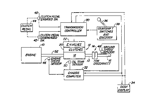
FIG. 1 is a schematic block diagram of a microprocessor-
based transmission control system to which the present
invention is applicable.
FIG. 2a is a schematic representation of a transmission
to which the present invention is applicable.
FIG. 2b illustrates in greater detail a portion of the
transmission of FIG. 2a.
3~ FIG. 3 is a simplified logic flow diagram of an algorithm
which is performed by the method of the present invention and
which determines if a shift is required.
r~
-
FIG. 4 is a simplified logic flow diagrams of a main loop
algorithm which is performed by the method of the present
invention.
FIG. 5 is a simplified logic flow diagram of an
initialization algorithm which is performed by the main loop
algorithm of the present invention.
FIGs. 6a and 6b form a simplified logic flow diagram of a
pressure funtion algorithm which determines an element ~
pressure value Press(el) from pressure values Peol provided by
the algorithm illustrated by FIG. 7.
FIG. 7 is a simplified logic flow diagram of an algorithm
which determines the pressure value Peol from stored pressure
values PE(i) which are stored in a table in memory.
FIGs. 8a and 8b form a simplified logic flow diagram of a
transfer funtion algorithm which determines a duty cycle for a
valve command signal from the Press(el) values provided by the
algorithm of FIGs. 6a and 6b.
FIG. 9 is a simplified logic flow diagram of a Time
Function algorithm which determines the times at which various
pressures are applied to the control valves 22.
FIG. 10 is a signal versus time diagram which illustrates
how the duty cycle value would vary as a function of time for
the shift corresponding to the data shown in a Sample Shift
Table.
FIG. 11 is a pressure versus time diagram which
illustrates how the pressure applied to a transmission clutch
element would vary as a function of time for the shift
corresponding to the data shown in the Sample Shift Table.
Detailed Description
As shown in FIG. l, a vehicle power train includes an
engine 10 which drives a power shift transmission 12, which
has an output shaft 13, which, via a conventional tow
disconnect mechanism 14, drives an output drive shaft 16 which
is connected to drive wheels (not shown). The power shift
transmission 12 includes a transmission or gear box 18 which
is operated by a set of pressure operated control elements or
clutches 20 which are controlled by a correspondinq set of
~27~
_
solenoid operated control valves 22. The transmission 18 may
be a transmission such as described in US Patent No.
5,011,465, issued 30 April 1991 to Jeffries et al., and
assigned to the assignee of this application.
The power shift transmission control system includes a
transmission control unit 30, a chassis computer 32 and a dash
display 34. The transmission control unit 30 and the chassis
computer 32 are preferably microprocessor-based electronic
control units. Manual control is achieved via a gearshift
lD lever 36. A gearshift switches and encoder unit 38 provides
signals representing the position of the lever 36 to the
transmission control unit 30. A clutch engagement switch 40
and a clutch disengagement switch 42 provide signals
representing the position of a clutch pedal 44. The chassis
computer 32 receives signals from an engine speed sensor 46, a
ground speed sensor 48 and a transmission oil temperature
sensor 50. The chassis computer 32 sends information from
these sensors to the transmission control unit 30.
The transmission control unit 30 includes a commercially
available microprocessor (not shown) which executes a computer
program which implements operation of the clutch control
method described hereinafter. The transmission control unit
30 also includes valve drivers (not shown) which provide
variable duty cycle pulse-width-modulated voltage control
signals to the control valve units 22. The transmission
control unit 30 and the valve drivers (not shown) will
generate such control signals as a function of various sensed
and operator determined inputs in order to achieve a desired
pressure in the clutches 20 and to thereby control the
shifting of the transmission 12 in a desired manner. The
method of the present invention is implemented by the control
unit 30 which executes the computer program which is listed in
the microfiche appendix. The computer program listing is in
Motorola 68HC11 assembly language.
Referring to FIGs. 2a and 2b, the control elements of
transmission 12 include a set of brake elements Bl, B2, B3, B4
and B5, and a set of clutch elements Cl, C2, C3, and CL0. The
~ input shaft 52 is connected by splines 54 to the clutch drum
56 of clutch C1 and of clutch C2 (not shown in FIG. 2b). The
drum 56 in turn is splined to the clutch separators 58 of
clutch C1. The clutch disks 60 of clutch C1 are splined to
the clutch hub 62 of clutch C1. The clutch hub 62 is splined
to a first intermediate shaft 64. The first clutch C1 is
provided with a piston 66 for activating the clutch C1 by
compressing the clutch separators and disks 58, 60. A spring
68 is provided to bias clutch C1 out of engagement. For
further information regarding the details of such a
transmission reference is made to US Patent No. 5,011,465.
One of the control valves 22 associated with clutch C1 is
schematically illustrated in FIG. 2b. The control valve 22 is
connected to a pump 70 and to sump or reservoir 72 and
controls pressurization of piston 66 in response to signals
received from transmission control unit 30. Each of the brake
and clutch elements is controlled by a similar corresponding
control valve 22. Each of the control valves 22 is preferably
a two-stage electrohydraulic valve such as a valve model No.
151140 manufactured by FEMA Corp. Such a valve has a main
stage such as described in U.S. Patent No. 4,741,364, issued 3
May 1988 to Stoss et al. and assigned to applicant~s assignee.
The following description makes use of a number of
symbols or acronyms which are defined as follows:
CLDspd is a speed threshold used when the clutch pedal is
fully disengaged to determine if a "direct engagement" or a
~rolling clutch disengaged~ shift should occur.
Ne is engine speed.
Nemax is the maximum engine speed which can be used in
the transfer curve equation.
Nemin is the minimum engine speed which can be used in
the transfer curve equation.
P(f) is the shift table pressure value which is used to
signal additional element fill or maximum pressure required.
P(w) is the shift table pressure value which is used to
signal an element base wakeup pulse.
~ ~ ~ r;~ i ~
Pcd is the maximum pressure command used during a
"rolling clutch disengaged shift".
Pch is the pressure command used for centrifugal head
pressu~re adjustment.
PE(i) is the pressure value of a specific shift table
entry.
Peol is the pressure value determined by using the shift
table entries for pressure, slope, and time.
Pfill is the special value of Peol used during an element
fill (this is larger than Pmax).
Pfill(el) is the fill pressure of an element as
determined by the calibration procedure.
Pmax is the value of Peol which is the highest normal
pressure command.
Poffset is a scaling value which allows Press(el) to be
less than Pfill(el).
Press(el) is the pressure command for the element as
determined by the Pressure Function subroutine.
Pwake is the special value of Peol used during an element
base wakeup pulse.
SE(i) is the slope value of a specific shift table entry.
t(abs) is the timer value used to determine absolute time
during a shift.
t(bp) is the timer value used to determine the time a
base wakeup pulse has been in progress.
t(sft) is the time value used to retreive proper data
from the shift table.
tE(i) is the time value corresponding to a specific set
of shift table data.
tfc is the time adjustment used for fill compensation.
To is the transmission oil temperature.
Tomax is the maximum oil temperature which can be used in
the transfer curve equation.
Tomin is the minimum oil temperature which can be used in
3~ the transfer curve equation.
tr is the "realignment time", or the time value at which
the shift is converted from relative to absolute time for all
elements.
twake(el) is the time of the base wakeup pulse for an
element as determined by the calibration procedure.
twake(max) is an arbitrary time used to keep negative
numbers from occurring during calculations.
tla (or tlb) is an "intershift pause time" or time
between shifts.
Vbat is the input voltage to the controller.
Vmax is the maximum voltage which can be used in the
transfer curve equation.
Vmin is the minimum voltage which can be used in the
transfer curve equation.
Refering now to FIGs. 3-9, the algorithms and subroutines
shown therein are executed once for each of the eight valves
every 20 milliseconds, in the same order.
FIG. 3 shows a test routine 100 which is executed to
determine if a shift of the transmission 12 is re~uired. This
routine is a portion of an overall program which is constantly
and repeatedly executed during normal operation. Step 102
tests if the commanded gear (determined by the position of the
shift lever 36) is the same as current gear. If it isn't,
then step 104 checks if a shift is in progress. If there
isn't one in progress, then step 106 checks if the "intershift
pause time" tla or tlb has elapsed since the last shift. tla
and tlb are a pause times between shifts so that the timing of
the shifts can be coordinated. It has been found there may be
a problem if the shifts get crowded too close together. So, a
pause time is used in between the shifts, and the pause time
must elapse before another shift is performed. For this
purpose, a timer is started after a shift is complete. There
are two different intershift times depending on whether the
tractor is in a working or transport gear. Additional
3~ intershift times could be created depending on the needs of
the tractor.
,
' ~12~1~5
w
The final check in step 108 is the position of clutch
pedal 44. If the pedal 44 is not completely disengaged, a
shift sequence is begun. If the pedal 44 is completely
disengaged, the wheel speed of the vehicle is compared in step
110 to CLDspd. If wheel speed is greater than CLDspd, a shift
sequence is begun. If the wheel speed is less than CLDspd,
then the clutch elements which correspond to the COD anded
gear are engaged directly with no modulation. This is ~o
remove delay when shifting while the vehicle is not moving, or
moving very slowly (for example, when sitting at a stop sign).
While the present invention is not directed to this test
routine 100, it is included to show what leads up to the
starting a shift.
Turning now to FIG. 4, there is shown the main shift
control loop or process 200 which is performed for each
element during a shift. First, an "Initialize Function" 300
is performed for each element at the beginning of a shift. At
400 a "Pressure Function" is executed to determine the
pressure command which represents the pressure which is to be
applied to the particular clutch. This is followed by a
"Transfer Function" 500 which determines the electrical duty
cycle which, if applied to the appropriate valve, will produce
the pressure determined by the "Pressure Function". Next, the
"Time Function" 600 determines or controls the increment of
timers to control the timing of events during a shift. Then
step 202 causes exiting of the main shift control loop if a
"shift done" flag is set. Otherwise, control is directed to
steps 204 and 206 which commands a new duty cycle to one of
the valves 22 at the appropriate time.
The "Initialize Function~ 300 is more fully illustrated
in FIG. 5. Basically, in steps 302-314 all the counters,
flags, and timer values are initialized for the shift. In
steps 306-310 sensed engine speed and oil temperature values
are read, and these values are used with an oil
temperature/engine speed compensation table (not shown) stored
in memory to determine "t(fc)" values. The "t(fc)" value
represents the number of 20 millisecond steps by which an
- absolute timer is incremented. Step 306-312 can be described
as "fill pulse" compensation whereby the filling duration of
clutch elements is adjusted to compensate for variations in
engine speed and oil temperature. This is represented in the
timing diagram of FIG. 11 by the duration labeled "t(fc)"
between 0 and 100 milliseconds. In a typical shift the
oncoming elements are commanded on or pressurized by a
variable duration fill pulse to assure complete filling of the
element being filled. The timing of the beginning of a shift
may be advanced by up to five (100 msec) time intervals,
depending on oil flow (engine speed) and oil viscosity (oil
temperature). This adjusts the timing of oncoming elements to
compensate for slower valve response with cold oil and slower
fills with lower pump flow during the important fill period at
the beginning of a shift. Off-going and non-changing elements
are adjusted the same time amount, but this has no overall
effect on them.
Turning now to FIGs. 6a and 6b, the "Pressure Function"
400 determines a pressure command value Press(el) which used
later by the "Transfer Function~ 500. The ~Pressure Function"
in step 402 sets Press(el) equal to a Pfill(el) value which is
determined by a calibration procedure such as described in US
Patent No. 5,224,577 and assigned to the assignee of the
present application. Then in step 404 an offset value
"Poffset~ is subtracted from Press(el) so that no negative
numbers have to be manipulated.
Next, a "Find Peol~ subroutine, (described later with
reference to FIG. 7) is executed to retreive pressure and
slope values from data stored in a shift table in memory, and
calculate a pressure value Peol therefrom. The algorithm then
returns to the Pressure Function of FIG. 6a where steps 406
and 408 set Press(el) to zero if Peol is equal to zero. Steps
410 and 412 set Press(el) to a maximum pressure command value,
Pfill, if Peol is equal to P(f) for times when extra fill oil
is needed on oncoming elements, or when maximum pressure is
desired. Steps 414 and 416 set Press(el) to Pwake if Peol is
equal to P(w). Pwake is a special value which is used to
$ ~
-
signal the start of a "wakeup" pulse, which is the initial
pressurization period of an oncoming element, and which is an
identifier which is used by the Time Function of FIG. 9 to
start incrementing a base pulse timer value t(bp).
If Peol is not one of these three special cases, then
step 418 adds Peol to Press(el). Then step 420 determines if
the element requires centrifugal head compensation. If it is,
then steps 422-426 reads the engine speed, determines the
appropriate pressure value Pch from a table that is stored in
memory, and adds Pch to Press(el). In this manner, steps 420-
426 add to Press(el) a centrifugal head compensation factor.
The centrifugal head compensation process is more fully
described in the aforementioned U.S. Patent No. 5,224,577.
Steps 428 and 430 operate to limit Press(el) to a maximum
pressure Pmax in order to prevent overflow during later
calculations. Pmax is a maximum valve duty cycle value, but
is smaller than Pfill and Pwake, so the controller can
distinguish between them in later calculations. Next, step
432 exits this subroutine if the clutch is engaged.
Otherwise, this subroutine proceeds to steps 434 and 436 which
limit Press(el) to a pressure value Pcd, if the tractor is
moving and the clutch is disengaged. This allows the
transmission elements to slip and reduce engagement shock due
to the inertia of the transmission 18 being transmitted to the
rear axle (not shown) because in this drive train the clutches
are located at the front of the transmission 18 next to the
engine 10. Note that the P(f) and P(w) values are not
affected by this, so the oncomimg elements still fill
correctly. In this manner the "Pressure Function" 400
determines the pressure command value Press(el).
FIGs. 8a and 8b illustrate the "Transfer Function" 500.
The output pressure of the electro-hydraulic valves 22 may be
described as a linear function of electrical duty cycle.
Ideally, this function can be described by a linear equation
of the form Y = mX + b where Y = Valve command, X = Press(el),
m is a slope term, and b is an offset term. The "Transfer
Function" 500 begins at step 502 which fetches the Press(el)
value. Steps 504-508 set the duty cycle value to zero and
applies this duty cycle value to the valve driver (not shown)
for the approriate one of valves 22 if Press(el) equals zero.
Steps 510-514 set the duty cycle value to 95% and applies this
duty cycle value to the valve driver (not shown) for the
approriate one of valves 22 if Press(el) is greater than or
equal to Pmax. This turns the valve driver fully on and
causes the valve 22 to provide the maximum possible pressure.
Steps 516-524 check a battery voltage value, Vbat, and
limit Vbat between minimum and maximum values. Steps 526-534
check the engine speed value, Ne, and limit Ne between minimum
and maximum values. Steps 536-544 check the oil temperature
value, To, and limit To between minimum and maximum values.
Next step 546 calculates the duty cycle value,
Valve Cmd(%) according to the following equation:
Valve Cmd(%)=
[Int + K1(Vbat) + K2(Ne) + K3(To)] +
[Slope + K4(Vbat) + K5(Ne) + K6(To)][Press(el)],
where Int is the intercept of a non-corrected transfer curve,
where Slope is the slope of a non-corrected transfer curve,
and K1-K6 are empirically determined constants. The result
from step 546 is a valve command which is adjusted or
compensated as a function of variations in battery voltage,
engine speed and oil temperature. Step 548 applies this valve
command to the appropriate valve driver.
While this equation is linear for a given set of input
conditions, the real world provides too many variations.
Experimentation has determined that, for the particular valves
used in this system, the only two factors found to be
significant are changes in input voltage and pressure to the
valve. While valve voltage can be measured directly, the
change in input pressure is determined by watching oil
temperature and engine speed (if a reliable, low cost pressure
transducer was available, this could be measured directly).
To prevent a faulty instrumentation reading from giving
an unsuitable result, maximum and minimum values are set for
~ 1~3,~
each of the inputs. If there are any other inputs which the
valve responds to, these additional factors could be added to
the equation.
The following descriptions of FIGs. 7 and 9 are best
S understood in relation to the following Sample Shift Table
which is an example of data which is stored i~ memory and
which is utilized by the algorithms in connection with a
particular shift. In this sample table element A is an on-
coming element and element B is an off-going element. It
should be understood that other shifts would have different
shift tables. It should also be understood that more than one
pair of elements can be changed during a shift. The slope
SE(i) is expressed as the amount of pressure change per time
interval, and the pressure PE(i) is the relative pressùre (to
the fill pressure) desired at that point, plus an offset
pressure Poffset.
SAMPLE SHIFT TABLE
Element A Element B
tE(i) SE(i) PE(i) tE(i) SE(i) PE(i)
i (msec) (kP/20ms) (kP) (msec) (kP/20ms) (kP)
1 0 0 1593 0 -30 1100
2 100 0 1680 400 0 500
3 600 0 0 50~ 0 0
4 620 0 160
920 0 160
6 940 0 600
7 1040 20 600
8 1300 0 1593
Refering now to FIG. 7, the "Find Peol" subroutine 700
retreives from the shift table the appropriate pressure and
slope values, PEti) and SE(i), and calculates the value of
Peol which is supplied to the Pressure Function 400 of FIGs.
6a and 6b. First, step 702 sets an index i equal to 1. Then
step 704 compares a shift timer value t(sft) (supplied by the
Time Function described later with reference to FIG. 9) to the
~1 2 ~
next stored timer value tE(i+l). If t(sft) is less than
tE(i+l), then steps 706-712 fetch the PE(i) and SE(i) values
from the shift table and calculates the Peol value from the
equation: Peol = PE(i) + SE(i) x [t(sft) - tE(i)].
Steps 714 and 718 clear a "shift done" flag if tE(i) is
not the last entry in the table and returns control to step
406 of the Pressure Function of FIG. 6a. Steps 714 and 716
sets the "shift done" flag if tE(i) is the last entry in the
table and returns control to step 406 of the Pressure Function
of FIG. 6a. Thus, as long as t(sft) is less than tE(i~l) the
Find Peol subroutine will fetch the pressure and slope values
corresponding to tE(i) from the shift table. If t(sft) is not
less than tE(i+l), then step 704 directs the subroutine to
step 706 which increments the index i by 1 and returns control
to step 704. Steps 704-712 will then fetch the pressure and
slope values from the next row of the shift table.
Reference is now made to the Time Function 600
illustrated by FIG. 9. The Time Function generates the shift
timer values t(sft) which are used by the Find Peol subroutine
to extract data from the shift table. If no shift is being
commanded and the Wakeup pulse flag has not been set, then
steps 602, 616, 624 and 626 merely increment the absolute
timer value t(abs) by 1, sets a shift timer value t(sft) equal
to t(abs) and returns this t(sft) value for use by next
operation of the Find Peol subroutine.
If in step 602 Press(el) is equal to Pwake (the special
value indicative of a "wakeup" pressure pulse), then the
algorithm proceeds to step 604 which increments a base pulse
timer value t(bp) by 1. Then, step 606 compares t(bp) to
twake(el), which is a timer value corresponding to the time at
which a wakeup pulse is to be ended. Before this time has
occured, t(bp) will not be equal to twake(el) and step 606
directs contro~ to step 608 which increments the absolute
timer value t(abs) by 1. The shift timer value t(fst) remains
unchanged and this unchanged t(sft) value is returned for use
by next operation of the Find Peol subroutine. The algorithm
2 1 ~ 7 ~
will continue to loop through steps 602-608 until the time the
wakeup pulse is to be ended.
At the time the wakeup pulse is to be ended t(bp) will be
equal to twake(el) and step 606 directs control to step 610
which sets a wakeup pulse flag, to step 612 which increments
the base pulse timer value t(bp) by 1, and to step 614 which
calculates the shift timer value t(sft) according to the
equation:
t(sft) = t(abs) + twake(max) - twake(el),
where twake(max) is another arbitrary number which is added so
that all of the numbers will be positive and twake(el) is the
duration of the wakeup pulse for a particular one of the eight
shift elements being applied.
Since the wakeup pulse has ended, Press(el) will no
longer equal Pwake. Thus, the next time the Time Function is
executed, step 602 will direct control to step 616, and step
616 will direct control to step 618 because the wakeup pulse
flag has been set. Step 618 increments the timer value t(abs)
by 1. Step 620 compares t(abs) to a "realignment time" value
tr. If t(abs) is less than the "realignment time" value tr,
then step 622 sets t(sft) equal to [t(abs) + twake(max) -
twake(el)] and returns this t(sft) value for use by next
operation of the Find Peol subroutine. Thus, in the interval
between the end of the wakeup pulse and a "realignment time",
the shift timer value t(sft) will be a function of twake(el),
which may be different for each particular element or clutch
being controlled.
When the realignment time occurs, for example at t(abs)
equal to 420 milliseconds, step 620 will thereafter direct
control to step 628. Step 628 sets t(sft) egual to [t(abs) +
twake(max)] and returns this t(sft) value for use by next
operation of the Find Peol subroutine. Thus, after the
"realignment time", the shift timer value t(sft) will be
independent of twake(el) and will be the same for all
elements. It should be noted that t(sft) is the same for
oncoming and offgoing elements even though the oncoming is
t(abs) ~ twake(max) and the offgoing is just t(abs). This is
because the time values are adjusted in the shift tables. As
a result, after the "realignment time", the timing of all
elements will be a function an identical shift timer value
t(sft). This permits precise timing of each on-coming element
relative to the other elements before the shift reaches the
critical point where one element is turned off and stops
transmitting torque and another element is turned on and
begins transmitting torque (element swapping).
To summarize, the absolute time value t(abs) is
incremented every time the algorithm is executed. Prior to
application to the control element of a fill pressure pulse, a
shift time value t(sft) is set egual to the absolute time
value t(abs).
In response to a wakeup command, pressure is applied to
the clutch for a predetermined duration, represented by
twake(el), in order to fill the element. During this fill
period a base pulse time value t(bp) and the absolute time
value t(abs) are periodically incremented. However, during
this fill period the shift time value t(sft) is not
incremented.
When the base pulse time value is equal to a
predetermined wakeup time value (meaning the clutch is
filled), the wakeup flag is set, the absolute time value
t(abs) is incremented and the shift time value t(sft) is set
equal to the absolute time value plus a maximum time value
less the fill duration time value twake(el). After the wakeup
flag is set and the control element is filled, the absolute
time value is incremented and compared to a realignment time
value tr. If the absolute time value t(abs) is less than the
realignment time value tr, the shift time value t(sft) is set
equal to the absolute time value t(abs) plus the maximum time
value less the fill duration time value twake(el).
A key aspect of the present invention is that, since
twake(el) will be different for each element, therefore, after
an element has been filled, and before the realignment time,
the shift time value t(sft) resulting from step 622 will be
different for each oncoming element. As a result, the timing
2~ ~,7~
of pressurization events during this period will be unique and
individual for each different element or clutch 20 of the
transmission 18, and will be a function of the twake(el) value
for that particular element.
If, in step 620, the absolute time value t(abs) is not
less than the realignment time value tr, it means that the
realignment time has been reached, and the shift time value
t(sft) is set equal to the absolute time value t(abs) plus the
maximum time value. As a result, after the realignment time
has been reached, all pressurization events will be controlled
by the same identical time value, namely [t(abs) +
twake(max)]. This permits precise synchonization of pressure
control after the realignment time.
After each determination of the shift time value, the
shift time value is compared to one of the stored time
reference values and an appropriate one of the stored pressure
command values and slope values is selected from memory and a
pressure signal is applied to the control element. If the
time shift value is not less than the time reference value,
the time reference value is updated to the next sequential
time reference value. After a realignment time, all elements
are controlled as a function of an identical time value based
on the absolute time value.
~efering now to FIGs. 10 and 11, the signal versus time
diagrams therein illustrates how the duty cycle values and
element pressures would vary as a function of time for the
shift corresponding to the data shown in a Sample Shift Table.
The duty cycle value and pressure for the on-coming element or
clutch, element A, are indicated by the solid lines and the
duty cycle value and pressure for the off-going element or
clutch, element B, are indicated by the dashed lines. The
cross-hatched area between t(abs) = 0 and 100 milliseconds
corresponds to the variable portion of the fill time as
determined by the fill compensation value t(fc) derived by the
Initialize Function 300 of FIG. 5. The remaining duration of
the fill time (to approximately 240 milliseconds) is
determined by the twake(el) calibration value which is unique
4~
-
for each element. The duration of the 0% duty cycle value
beginning at t(abs) = 240, and the timing of pressurization of
element A at t(abs) = 260 milliseconds is a function of
twake(el) and is therefore unique for element A. After the
realignment time, at t(abs) = 420, timing of both elements A
and B is controlled as a function of identical time values
based on t(abs). This permits precise relative timing of the
transfer of torque carrying from element B to element A during
the period from t(abs) = about 450 milliseconds to completion
of the shift at t(abs) = about 800 milliseconds.
A portion of the disclosure of this patent document
contains material which is subject to a claim of copyright
protection. The copyright owner has no objection to the
facsimile reproduction by anyone of the patent document or the
patent disclosure, as it appears in the Patent and Trademark
Office patent file or records, but otherwise reserves all
other rights whatsoever.
While the invention has been described in conjunction
with a specific embodiment, it is to be understood that many
alternatives, modifications and variations will be apparent to
those skilled in the art in light of the foregoing
description. Accordingly, this invention is intended to
embrace all such alternatives, modifications and variations
which fall within the spirit and scope of the appended claims.
18