Note: Descriptions are shown in the official language in which they were submitted.
Ba~htub Lift for Handicapped Persons 212 716 8
BACKGROUND OF THE INVENTION
... . .
The invention concerns a bathtub lift with a lifting
plate upwardly and downwardly guided on a support frame
and actuated by a hydraulic lif~ing device, and a valve
device featuring an inlet valve and an outlet valve whose
valve plungers are actuatable as required by a hand-
operated rocker, whereby the two valve plungers are of
identical design, displaceably guided with parallel axes
in a valve housing and preloaded in their closed position
with inbuilt springs, and a connection leading to the ~ -
lifting device is connected to an outlet opening when the
outlet valve is open. ~ ;
,:
US Patent 3,280,409 shows such a bathtub lift. The valve
device is positioned at the side and at a distance from , -
the support frame and from the lifting plate. If the
former is raised to its limit of travel, its upward
motion is limited by an adjustable stop. The pressure in
the hydraulic lifting device increases up to the supply
pressure in the pressurized water line. The hydraulic
lifting device is subjected to high load in the process.
EP Patent 00 74 460 shows a bathtub lift on which the -
lifting device consists of a flexible hose. If such hoses
are subjected fre~uently and for extended periods to the
full pressure of the water supply line, there is a risk
of leakage.
US Patent 4,624,019 shows a lifting appliance with a
metal lifting cylinder. A three-way valve positioned at a
distance from the lifting plate is actuated by a hand-
operated pivoted lever acting upon a Bowden cable. At its
limit of travel, another Bowden cable draws an actuating
rocker of the three-way valve towards another actuation
position so that the lifting cylinder is disconnected
from the pressurized water supply; the discharge valve,
however, is opened as a result and the lifting plate
`` 2 21271~8
descends.
S~MMARY OF THE INVENTION
The object of the invention is to improve a bathtub lift
with a valve device of the type described above in such a
way that the inlet valve automatically closes at
precisely the lifting plate's limit of travel without
affecting the outlet valve.
According to the invention, the valve device is fastened
beneath the lifting plate and the rocker rests in a
recess in the lifting plate and projects slightly above
its upper face; at the valve plunger of the inlet valve a ~-
lifting element engages which, at the lifting plate's
limit of travel, cooperates with a control arm
displaceably guided beneath said lifting plate and lifts
the valve plunger into its valve closed position whereby
the motion of the control arm is derived from that of the
support frame featuring two scissor frames.
The rocker does not require a spring means of its own to
preload it towards its neutral position because tpe two
valve springs effect this automatically. Thanks to the
positioning of the valve device on the underside of the -
lifting plate, it is possible to move the inlet valve
into its closed position by means of a simple mechanical
connection between a scissor frame of the support frame
, and the valve device when the support frame reaches its
limit of travel. The pressure in the lifting device then
has precisely the value corresponding to the load of the
lifting plate which is well below the pressure in the
water supply line. In accordance with the invention, the
inlet valve is closed with a position-dependent
mechanism; a particularly beneficial feature is the
extremely short stroke of the valve plunger of less than
2 mm. Any play in the motion of the rocker cannot have
any effect on this automatic closure of the inlet valve.
. :
.
~ . 4! ~ ~ '
- ' 3 21271~8
In accordance with an embodiment of the invention, the
outlet valve is at the same time a safety valve for
limiting the pressure in the lifting device. When the
lifting support frame reaches its limit of travel defined
by the stop, the pressure in the lifting device rises. At
a value beneath the water line pressure, though above the
pressure needed for lifting heavy persons, the outlet
valve opens as the spring is selected for this pressure
value. As soon as the pressure falls below this value, ;~
the outlet valve closes. Even in the event of failure of
the position-dependent closure of the inlet valve, only a
limited pressure can build up in the lifting device.
BRIEF DESCRIPTION OF THE DRAWING
It shows:
FIG. 1 a side view of the bathtub lift,
FIG. 2 a top view of a detail of the lift showing the
guide support frame in the lifting plate's
uppermost position,
FIG. 3 a partially sectional side view of the valve
device beneath the lift's lifting plate, and
FIG. 4 a vertical section through the valve device.
DETAILED DESCRIPTION
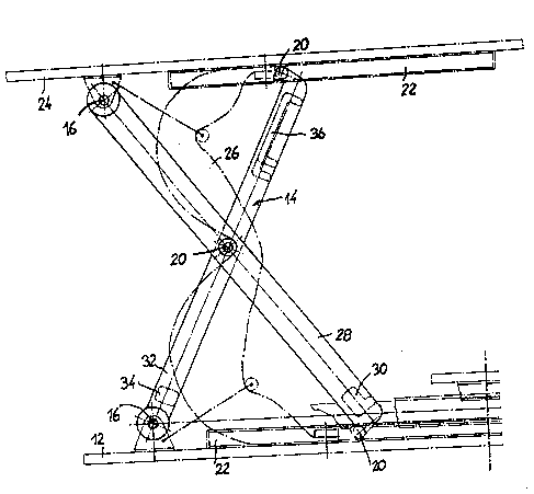
The basic design of the bathtub lift is shown in Fig. 1.
Resting on a base plate 12 is a support frame 14
featuring two scissor frames 28, 32 whereby the inner
scissor frame 32 is rotatably guided about two fixed
rotary bearings 16 on the base plate and the outer
scissor frame 28 features two slide bearings 20 which are
~ 4 ~127~68
displaceably guided in guide rails 22 on the base plate
12. The two scissor frames 28, 32 are connected together
at their mid-length positions by a joint rotary bearing
20. The support frame 14 supports a lifting plate 24 on
the underside of which two fixed rotary bearings 16 are
provided for the outer scissor frame 28 as well as two
guide rails 22 in which the slide bearings 20 of the
inner scissor frame 32 are longitudinally displaceable.
At its base, the outer scissor frame 28 has a cross strut
30 and the inner scissor frame has a bottom cross strut
34 and a top cross strut 36. The two scissor frames each
consist of single-piece moulded plastic parts. A lifting
hose 26, which is closed at its two ends, is attached
with its bottom end to the base plate 12 and clamped with
its top end to the underside of the lifting plate 24.
Near to the outer edge of the lifting plate 24 is a valve
device 40 which is screwed onto the underside of the
lifting plate 24. The valve housing 42 of the valve
device 40 features a connecting sleeve 44 to which a
pressurized water supply hose is connectable.
Perpendicularly beneath the connecting sleeve 44 is
another connecting sleeve 46 to which a hose leading to
the lifting hose 26 can be attached. As is shown
particularly by Fig. 4, the valve housing 42 contains an
inlet valve 48 and an identically designed outlet valve
50. Each of the two valves 48, 50 features a valve
plunger 52 which is displaceably guided with a vertical
axis in a stepped borehole in the valve housing 42,
features a valve plate 54 with a ring seal close to its
bottom end and is preloaded by a helical spring 56
against a valve seat 58. Above the valve seat 58, a first
annular chamber 60 is formed into which the borehole of
the connection 44 opens. Situated beneath the valve seat
58 is a second, in diameter slightly larger, annular
chamber 62 into which the borehole of the connection 46
opens.
The outlet valve 50 contains a first annular chamber 64
- ~ 5 21~7~ ~g
above the valve seat 58 and, downstream ~rom the valve
seat 58, a second annular chamber 66 containing the valve
spring 56. A downwardly inclined vent hole with outlet
opening 68 opens into this second annular chamber 66. The
bottom annular chamber 62 of the inlet valve 48 is
connected via an upwardly inclined borehole 70 to the
upper annular chamber 64 of the outlet valve 50. The axis
of the borehole is situated in the central vertical
longitudinal plane of the valve housing 42 and intersects
the axes of the two valve plungers 52. The upper end of
the connecting borehole 70 is closed by a threaded
stopper, as shown schematically at 72.
The two valve plungers 52, whose axes are vertical and
parallel, project from the top of the valve housing 42
and feature a neck-like constriction 74 beneath the
plunger head. A rocker 76 is rotatably mounted about a
transverse axis 78 on the valve housing 42 on the top in
a middle transverse plane at equal longitudinal distances
from the two valve plungers 52. On the top, the rocker 76
has two pushbutton fields 80, 82 which merge into one
another on a continuous curve. On the underside of the
rocker 76 are two projections with actuation faces 84, 86
which are positioned close to the heads of the valve
plungers 52 when the rocker 76 is in its neutral position
shown in Fig. 4. The lifting plate 24 features a
rectangular recess 88 for the rocker 76 so that the
rocker 76 unly projects slightly above the upper face of
the lifting plate 24.
If the user of the bathtub lift presses the pushbutton
field 80 of the rocker 76, the valve plunger 52 is
displaced downwards and the connecting sleeve 46 leading
to the lifting hose 26 communicates with the connecting
sleeve 44 leading to the pressurized water supply with
the result that the lifting hose 26 is filled with water
and the lifting plate 24 is raised. If the user releases
the rocker 76, the valve spring 56 causes the inlet valve
48 to close whereby the valve plunger 52 returns the
:
--~ 6 21271~
rocker 76 to its neutral position. If the user now
presses the pushbutton field 82 of the rocker 76, the
outlet valve 50 opens and the lifting hose 26 is drained
via the housing borehole 70 and the two annular chambers
64, 66 of the outlet valve 50 whereby the water is
discharged via the outlet opening 68.
In a simple embodiment, the two rails 22 of the lifting
plate 24 and/or the rails 22 of the base plate 12 are
equipped with a plastic element against which the
respective slide bearings 20 of the scissor frames 32 and
28 abut when the lifting plate 24 reaches its limit of
travel. The water pressure, possibly reduced by a
pressure reduction valve, then builds up in the inlet
valve 48 on either side of the valve seat 58 so that the
valve spring 56 closes the inlet valve.
The outlet valve 50 is also preferably designed as an
excess pressure valve whereby the strength of the valve
spring 56 must be dimensioned such that the valve 50
opens to reduce the pressure in the lifting hose 26 if
the adjustable working pressure ranging from
approximately 3 to 6 bar is fallen short of.
Instead of rigid mechanical stops, compressible plastic
bodies can be fitted in the rails 22 so that the motion
of the lifting plate 24 is damped on reaching its limit
of travel. With a simple piece of additional equipment, a
position-dependent closure of the inlet valve 48 can be ;
achieved. To this end, a hand-operated pivoted lever 90
is employed which features in its central area a
longitudinal slot 92 with an insertion opening and in
which the neck-like constriction 74 of the valve plunger
52 of the inlet valve 48 engages. This pivoted lever 90
is therefore supported by the valve plunger 52 of the
inlet valve 48 with low vertical play. The two ends of
the pivoted lever 90 are bent downward, with the right-
angled bend serving as the pivotal bearing of the pivoted
lever 90 on the valve housing 42. This right-angled bend
` ~` 7 2~27168
is situated between the transverse axis 78 of the rocker
76 and a projection on the upper face of the valve
housing 42. The other end of the pivoted lever 90 is
provided with a face 94 at an angle of approximately 60
from the horizontal. This angled end of the pivoted lever
90 is positioned between two side wall parts featuring
horizontal longitudinal holes 96 penetrated by the right-
angled piece 98 of a bar 100. In the two rails 22 of the
lifting plate 24 are two transversely aligned
longitudinal holes 102 which are penetrated by the bar
loO. A spring 104 (Fig. 2) draws the bar 100 to one set
of ends of the longitudinal holes 102. The right-angled
bend 98 then adopts the position indicated by a broken
line in Fig. 4 and is thus positioned at the end of the
longitudinal holes 96. If the slide bearing 20 of the
scissor frame 32 in the rails 22 now reaches a position
shortly before the lifting plate's 24 limit of travel,
the sliding piece 106 guided in the rails 22 makes
contact with the bar 100. The bar 100 is displaced a few
millimetres in a longitudinal direction against the
action of the readjusting spring 104. In the process, the
right-angled piece 98 comes into contact with the angled
face 94 of the pivoted lever 90 and, in the event of a
further displacement of the bar 100, the pivoted lever 90
is pivoted upward so that the valve plunger 52 of the
inlet valve 48 is drawn into its closed position. The
pivoted lever 90 thus acts here as a lifting element in
closing the inlet valve 43 with a position-dependent
mechanism even when the user presses the "down"
pushbutton field of the rocker 76.
. .
The described limit-of-travel closure is extremely
precise because it acts directly upon the valve plunger
52, thus eliminating the influence of any play of the
rocker 76. The necessary stroke of the two valve plungers
52 is extremely short and is in practice less than 2 mm.
The last-mentioned, position-dependent actuation of the
inlet valve 48 can be employed instead of a mechanical
T~ T~
: ~ ~ i T ~ r
8 2~ 271 6 g
stop in the rails 22 and in addition to such stops,
particularly if they are designed as dampers.
,
:
',. ; '','~
. .
I ~
.
"
.,:
~ '