Language selection

Search

Patent 2127325 Summary

Third-party information liability

Some of the information on this Web page has been provided by external sources. The Government of Canada is not responsible for the accuracy, reliability or currency of the information supplied by external sources. Users wishing to rely upon this information should consult directly with the source of the information. Content provided by external sources is not subject to official languages, privacy and accessibility requirements.

Claims and Abstract availability

Any discrepancies in the text and image of the Claims and Abstract are due to differing posting times. Text of the Claims and Abstract are posted:

  • At the time the application is open to public inspection;
  • At the time of issue of the patent (grant).
(12) Patent Application: (11) CA 2127325
(54) English Title: APPARATUS AND METHOD FOR CONTROLLING HUMAN LACTATION
(54) French Title: DISPOSITIF ET METHODE DE CONTROLE DE LA LACTATION CHEZ LA FEMME
Status: Deemed Abandoned and Beyond the Period of Reinstatement - Pending Response to Notice of Disregarded Communication
Bibliographic Data
(51) International Patent Classification (IPC):
  • A41C 03/04 (2006.01)
(72) Inventors :
  • MORRISSEY, SUZANNE E. (United States of America)
  • MORRISSEY, GERALD (United States of America)
(73) Owners :
  • SUZANNE E. MORRISSEY
  • GERALD MORRISSEY
(71) Applicants :
(74) Agent: GOWLING WLG (CANADA) LLP
(74) Associate agent:
(45) Issued:
(22) Filed Date: 1994-07-04
(41) Open to Public Inspection: 1996-01-05
Examination requested: 2001-06-14
Availability of licence: N/A
Dedicated to the Public: N/A
(25) Language of filing: English

Patent Cooperation Treaty (PCT): No

(30) Application Priority Data: None

Abstracts

English Abstract


An apparatus comprising a support having an outer surface and an inner
surface that is shaped to conform substantially to a human female breast and having a
protrusion which extends away from the support and is positioned to align substantially
with and contact a nipple of a human female breast prevents a human female breast from
lactating when placed over the breast. The present invention also provides a method for
controlling human lactation which utilizes the present apparatus and includes the steps of
placing and positioning the apparatus over the breast and applying pressure on the
apparatus sufficient to prevent lactation.


Claims

Note: Claims are shown in the official language in which they were submitted.

- 5 -
WHAT IS CLAIMED IS:
1. An apparatus for the control of human lactation comprising a support
having an outer surface and an inner surface that is shaped to conform substantially to a
human female breast, said inner surface having a protrusion with a nipple-contacting
surface extending away from said support and positioned to align substantially with and
contact a nipple of said human female breast when said apparatus is placed over said
human female breast, whereby said protrusion substantially prevents said human female
breast from lactating.
2. An apparatus according to claim 1, wherein said outer surface is
convex and said inner surface is 15 concave.
3. An apparatus according to claim 1, wherein said protrusion is
substantially the same size as said nipple.
4. An apparatus according to claim 1, wherein 20 said protrusion is
substantially larger than said nipple.
5. An apparatus according to claim 1, wherein the nipple-contacting
surface of said protrusion is concave.
6. An apparatus according to claim 1, wherein 25 said support is
constructed from a flexible material.
7. An apparatus according to claim 6, wherein said flexible material is
a plastic.
8. An apparatus according to claim 1 further comprising a brassiere
having a cup, wherein said support 30 is placed in side the cup of said brassiere.

- 6 -
9. An apparatus according to claim 8, wherein said brassiere is a
conventional brassiere.
10. An apparatus according to claim 8, wherein said brassiere is a
nursing brassiere.
11. An apparatus according to claim 1, further comprising an absorbent
breast pad placed on said inner surface of said support.
12. An apparatus for the control of human lactation comprising a
flexible support having an outer convex surface and an inner concave surface that is
shaped to conform substantially to a human female breast, said inner surface having a
protrusion extending away from said support and positioned to align substantially with and
contact a nipple of said human female breast when said apparatus is placed over said
human female breast, whereby said protrusion substantially prevents said human female
breast from lactating.
13. An apparatus according to claim 1, wherein 15 said apparatus further
comprises a brassiere with which said support is integrated.
14. A method for controlling human lactation comprising the steps of:
providing an apparatus comprising a support having an outer surface and an
inner surface that is shaped to conform substantially to a human female breast, said inner
surface having a protrusion with a nipple-contacting surface extending away from said
support and positioned to align substantially with and contact a nipple of said human
female breast when said apparatus is placed over said human female breast, whereby said
protrusion substantially prevent said human female breast from lactating,
placing said apparatus over said breast;
positioning said apparatus to align said protrusion substantially with and
contact said nipple of said breast; and
applying pressure to said apparatus sufficient to prevent said breast from
lactating.

- 7 -
15. A method according to claim 14, wherein said outer surface is
convex and said inner surface is concave.
16. A method according to claim 14, wherein said protrusion is
substantially the same size as said nipple.
17. A method according to claim 14, wherein said protrusion is
substantially larger than said nipple.
18. A method according to claim 14, wherein the nipple-contacting
surface of said protrusion is concave.
19. A method according to claim 14, wherein said support is constructed
from a flexible material.
20. A method according to claim 19, wherein said flexible material is
plastic.

Description

Note: Descriptions are shown in the official language in which they were submitted.


2127325
APPARATUS AND METHOD FOR
CONTROLLING EIUMAN LACTATION
S FIELD OF THE INVENTION
The present invention relates to an appalallls and method for controlling
lactation in human females.
BACKGROUND OF THE INVENTION
In recent years, breast feeding of newborn babies has seen a re~ulgence in
popularity. Breast feeding is becoming more popular for a variety of reasons relative to
both baby and mother. These advantages include increased protection of the infant from
illness through the development of protective antibodies, decreased risk of developing
childhood cancers, avoiding potential allergies to commercial infant form~ c, and
enhanced jaw, teeth, and speech development, among others. Furthermore, it has been
suggested that nursing mothers have a lower risk of developing breast cancer. Breast
feeding has also been suggested to improve the emotional bond between mother and child.
Although breast feeding is enjoying renewed use, it is not without
disadvantages. The outpouring of milk is known as the "let-down" or "milk-ejection"
reflex. A let-down can occur several times during a feeding. It is well known that the
milk-ejection reflex can be triggered at inapplopliate times by various stimuli. A baby's
crying, for example, may cause let-down in a nursing mother. This can result in let-down
at very inopportune times.
This inapplopl;ate let-down can be particularly 35 problematic for working
mothers who are nursing. Solutions designed to alleviate problems associated with
inappropl;ate let-down include absorbent breast pads or breast shields that operate,
essentially, as a well or reservoir to collect leaking milk. These solutions aredisadvantageous because of the limited capacity of both types of devices as well as the
likelihood that milk will leak into clothing despite their use.
It is also known that nursing mothers can apply direct ples~u~e to the
nipples with the heels of their hands or forearms to temporarily halt leakage. However,
this type of solution likewise presents obvious disadvantages for the nursing mother who is
ROC10:33700

212732~
- 2 -
working or otherwise in public. Therefore, there continues to be a need for apparatus that
can effectively conkol inopportune lactation in nursing mothers.
SUMMARY OF THE INVENTION
This invention relates to an al)pa~dlus and method for controlling human
lactation. The al~paldlus compri~es a support having an outer surface and an inner surface
that is shaped to conform subst~nti~lly to a human female breast. The inner surface has a
protrusion which extends away from the support and is positioned to align substantially
with and contact a nipple of a human female breast when the ~pal~lus is placed over the
breast. In this way, the prol~ ion substantially prevents the breast from lactating.
The a~alalus can be used alone or include a brassiere which the support is
either placed into or 30 integrated with (e.g., sewn into). The brassiere can be either a
conventional or nursing brassiere.
The present invention also provides a method for controlling human
lactation which utilizes the present apparatus. The method includes the steps of placing
the apparatus over the breast and applying pressure on the apparatus sufficient to prevent
lactation.
The apparatus and method of the present invention provide a convenient and
effective way to prevent inopportune milk leakage in the nursing mother. The apparatus
can be inexpensively constructed in a variety of shapes from a variety of materials.
BRIEF DESCRIPTION OF THE DRAWINGS
FIG. 1 is an exploded, perspective view of one embodiment of the apparatus
of the present invention and an absorbent breast pad.
FIG. 2 is a front view of an absorbent breast pad.
FIG. 3 is a side view of an absorbent breast pad. FIG. 4 is a perspective
view of the inner surface and protrusion of the present appaldlus.
FIG. 5 is a cross-sectional side view of FIG. 4 taken along line 5-5.
FIG. 6 is a perspective view of the outer surface of the support of the
present apparatus.
ROC10:33700

2127325
-
-- 3 --
FIG. 7 is a cross-sectional side view of the present a~pal~lus, including a
brassiere, placed over a human female breast.
FIG. 8 is a is a cross-sectional side view of an alternative embodiment of
the inner surface of the support and protrusion of the present invention.
DETAILED DESCRIPTION OF THE INVENTION
FIG. 1 is an exploded, perspective view of one embodiment of the a~paldlus
of the present invention and an absorbent breast pad. Apparatus 1 includes support 2
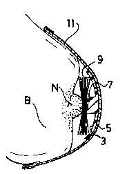
having an inner surface 3 and an outer surface 5. Inner surface 3 has a protrusion 7 which
extends away from support 2. Referring to FIG. 7, which is a cross-sectional side view of
one embodiment of the present appaldlus, including a brassiere, placed over a human
breast, protrusion 7 is positioned to align substantially with and contact nipple N of human
female breast B. Protrusion 7 operates to depress nipple N, whereby breast B is prevented
from lactating.
Support 2 is shaped to conform substantially to a human female breast.
Support 2 can, for example, be substantially circular with a concave/convex shape covering
a relatively small area of breast B as shown in FIG. 7. Support 2 can also take a variety
of other forms, substantially conforming to larger or smaller areas of breast B. Preferably,
support 2 is constructed in a substantially circular, concave/convex form and having a
radius from about 3 to 5 inches for m~xhllulll comfort and to allow use of the appalalus
on breasts of various sizes. Most preferably, support 2 is shaped such that suc;ion is
created between breast B and appaldlus 1 after al~palalus 1 is placed over breast B. The
suction helps to m~int~in the alignment of app~alus 1 with nipple N.
Support 2 can be made from a variety of flexible m~teri~l~ including
moldable plastic or rubber. Preferably, the support is made from a moldable, flexible
plastic material to allow m;-xi",l-", comfort and ease of manufacture. With reference to
FIGS. 4 and 6, perspective views of the inner and outer sllrf~ces, respectivèly, of
support 2, support 2 can be provided with holes 4 to allow air circulation around the
nipple and areolar region of breast B to prevent local irritation which commonly occurs in
nursing mothers.
ROC10:33700

2127325
- 4 -
Protrusion 7 can be produced separately and then attached to inner surface 3
or, preferably, integrated with inner surface 3. This preferred embodiment is shown by
FIG. 5, a cross-sectional side view of FIG. 4 taken along line 5-5. Protrusion 7 can be
integrated with inner surface 3 by molding protrusion 7 and support 2 together from the
same material. Protrusion 7 can be made from a variety of materials, as long as the
material is sufficiently rigid to depress nipple N when nipple N is contacted by protrusion
7. Exemplary materials for forming protrusion 7 include any of the rigid plastics
10 known in the art or sufficiently rigidized rubber.
Protrusion 7 can be any shape, so long as it is capable of depressing nipple
N when apparatus 1 is brought into contact with breast B and, in turn, pl~v~llL~ug lactation.
For example, protrusion 7, can be a flattened, planar surface formed in the center of the
inner surface 3 of support 2, as shown by FIG. 8, a cross-sectional side view of an
alternative embodiment of the inner surface of the support and protrusion of the present
invention. Protrusion 7 is preferably cylindrical, having a size approxim~ting a human
female nipple, as shown in FIG. 7. Most preferably, as illustrated by FIGS. 7 and 9,
nipple-contacting surface 8 of protrusion 7 is concave to make the appaldlus more
comfortable for the wearer and aid in keeping apparatus 1 in place.
Preferably, absorbent pad 9 is placed over inner surface 3 to absorb any
small amount of leakage resulting, for example, from mi~lignment of protrusion 7 and
nipple N. This embodiment is illustrated by FIGS. 1 and 7.
As shown by FIG. 7, the above-described appaldLus can be used by placing
it over breast B and applying pressure to the a~aldlus sufficient to depress and, in turn,
prevent milk release by nipple N of breast B. The amount of pressure need not be great
and can normally be produced by the force provided when appalalus 1 further comprises
brassiere 11. Support 2 can be placed inside the cup of brassiere 11 which is then put on
by the lactating woman, as illustrated by FIG. 7. Support 2 can either be manll~lly placed
into or actually integrated with (e.g., sewn into) the cup of the brassiere. Brassiere 11 can
be a conventional or nursing brassiere commonly worn by nursing mothers.
Although the invention has been described in detail, for the purpose of
illustration, it is understood 10 that such detail is for that purpose and variations can be
made therein by those skilled in the art without departing from the spirit and scope of the
invention which is defined by the following claims.
ROC10:33700

Representative Drawing
A single figure which represents the drawing illustrating the invention.
Administrative Status

2024-08-01:As part of the Next Generation Patents (NGP) transition, the Canadian Patents Database (CPD) now contains a more detailed Event History, which replicates the Event Log of our new back-office solution.

Please note that "Inactive:" events refers to events no longer in use in our new back-office solution.

For a clearer understanding of the status of the application/patent presented on this page, the site Disclaimer , as well as the definitions for Patent , Event History , Maintenance Fee  and Payment History  should be consulted.

Event History

Description Date
Time Limit for Reversal Expired 2005-07-04
Application Not Reinstated by Deadline 2005-07-04
Deemed Abandoned - Failure to Respond to Maintenance Fee Notice 2004-07-05
Amendment Received - Voluntary Amendment 2001-10-22
Letter Sent 2001-07-24
Inactive: Application prosecuted on TS as of Log entry date 2001-07-24
Inactive: Status info is complete as of Log entry date 2001-07-24
Request for Examination Requirements Determined Compliant 2001-06-14
All Requirements for Examination Determined Compliant 2001-06-14
Application Published (Open to Public Inspection) 1996-01-05

Abandonment History

Abandonment Date Reason Reinstatement Date
2004-07-05

Maintenance Fee

The last payment was received on 2003-07-04

Note : If the full payment has not been received on or before the date indicated, a further fee may be required which may be one of the following

  • the reinstatement fee;
  • the late payment fee; or
  • additional fee to reverse deemed expiry.

Patent fees are adjusted on the 1st of January every year. The amounts above are the current amounts if received by December 31 of the current year.
Please refer to the CIPO Patent Fees web page to see all current fee amounts.

Fee History

Fee Type Anniversary Year Due Date Paid Date
MF (application, 3rd anniv.) - small 03 1997-07-04 1997-06-26
MF (application, 4th anniv.) - small 04 1998-07-06 1998-07-02
MF (application, 5th anniv.) - small 05 1999-07-05 1999-06-30
MF (application, 6th anniv.) - small 06 2000-07-04 2000-06-30
Request for examination - small 2001-06-14
MF (application, 7th anniv.) - small 07 2001-07-04 2001-06-26
MF (application, 8th anniv.) - small 08 2002-07-04 2002-07-04
MF (application, 9th anniv.) - small 09 2003-07-04 2003-07-04
Owners on Record

Note: Records showing the ownership history in alphabetical order.

Current Owners on Record
SUZANNE E. MORRISSEY
GERALD MORRISSEY
Past Owners on Record
None
Past Owners that do not appear in the "Owners on Record" listing will appear in other documentation within the application.
Documents

To view selected files, please enter reCAPTCHA code :


To view images, click a link in the Document Description column. To download the documents, select one or more checkboxes in the first column and then click the "Download Selected in PDF format (Zip Archive)" or the "Download Selected as Single PDF" button.

List of published and non-published patent-specific documents on the CPD .

If you have any difficulty accessing content, you can call the Client Service Centre at 1-866-997-1936 or send them an e-mail at CIPO Client Service Centre.


Document
Description 
Date
(yyyy-mm-dd) 
Number of pages   Size of Image (KB) 
Representative drawing 1997-12-07 1 5
Drawings 1996-01-04 1 30
Description 1996-01-04 4 211
Abstract 1996-01-04 1 18
Claims 1996-01-04 3 91
Reminder - Request for Examination 2001-03-05 1 118
Acknowledgement of Request for Examination 2001-07-23 1 179
Courtesy - Abandonment Letter (Maintenance Fee) 2004-08-29 1 178
Fees 2003-07-03 1 31
Fees 1998-07-01 1 34
Fees 2000-06-29 1 28
Fees 2002-07-03 1 32
Fees 1999-06-29 1 28
Fees 1996-06-25 1 95