Note: Descriptions are shown in the official language in which they were submitted.
2127~;50
-- 1 --
TITLE OF THE lNV~ ION
Lid to hermetically seal a container and a
method for making same.
FIELD OF THE lNV~:N~ION
The present invention relates to a lid formed
of a thin sheet of plastics material for hermetically and
peelably sealing plastic containers.
BACRGROUND OF THE lNV~L.lION
Containers for food stuff, such as dairy
products, or for medicament, such as drug doses, are
generally covered by planar closures which are formed of
metallic foils, such as aluminum foil, molded plastics
and the like. The peripheral edge of these closures, or
lids, are coated with an adhesive bonding material or a
heat sealable coating so that they may be affixed to the
planar lip or rim of containers.
These lids are stacked in a dispensing magazine
and are removed one by one by a lid destacking and
feeding device which places them on containers where they
are heat sealed to the rim thereof.
The dispensing of lids made of metallic foils
is usually carried out without such problems as lids
adhering to one another due to presence of embossing
configurations usually found on such foils. On the other
2127650
hand, with lids made of a thin sheet of plastics
material, it has been observed that there exists a
suction effect on the lid being removed adhering to its
superposed lid in the magazine due to surface adherence;
S this is due to the absence of air entering behind the lid
as it is removed from the magazine.
OBJECTS AND STATEMENT OF THE INVENTION
The present invention is concerned with
overcoming the above problem of lids formed of thin sheet
of plastics material by so configurating the lid that,
during its removal from the stacking magazine, air entry
is made possible between the lid being removed and its
superposed lid to thereby prevent surface adherence
between the two.
This is achieved by forming, on the underside
of the lid, an annular pattern of separate bosses of
thermoplastic adhesive, the bosses being so disposed
relative to one another as to leave a gap therebetween
whereby, when the lid is in a stacked dispensing
relationship with similarly constructed lids, air
circulation is permitted between the edge of the lid to
the center thereof thereby preventing surface adherence
between successive lids as the lids are removed from the
stack. On the other hand, the disposition and the volume
of each boss are such that the thermoplastic adhesive
212765Q
-- 3
covers the full pattern area as the lid is heat sealed to
the rim of a container.
It is also an object of the present invention
to provide a method of making such lid.
The present invention therefore relates to a
lid formed of a thin sheet or laminated sheets of
plastics material, the lid having an underside coated, at
its peripheral edge, with a pattern of thermoplastic
adhesive to define a heat sealable marginal region
allowing the lid to be hermetically sealed to a
peripheral flange portion of a container. The pattern of
adhesive consists of fine particles forming bosses so
disposed relative to one another as to leave a gap
therebetween whereby, when the lid is in a stacked
dispensing relationship with similarly constructed lids,
air circulation between the edge of a lid to be dispensed
to a central region thereof is permitted thereby
preventing surface adherence to a superposed lid as the
lid is removed from the stack of lids.
The present invention is also concerned with a
method of making a lid having a pattern of bosses along
a marginal peripheral portion, comprising the steps of:
passing a strip of a thin sheet or laminated
sheets of plastics material between a pair of rollers,
including an upper pressure roller and a lower metal
21~765~
-- 4
roller; the latter having a portion thereof extending in
a bath of hot melt adhesive and having a cylindrical
surface displaying an engraved area and a non engraved
area;
scraping the hot melt from the surface of the
lower roller prior to the film being passed between the
rollers so that hot melt is removed from the non engraved
area whereby, as the sheet is passed between the rollers,
the hot melt in the engraved area is passed onto the
sheet to form bosses;
chilling the bosses; and
cutting the sheet to form lids having an
embossed area along the marginal peripheral portion.
Other objects and further scope of
applicability of the present invention will become
apparent from the detailed description given hereinafter.
It should be understood, however, that this detailed
description, while indicating preferred embodiments of
the invention, is given by way of illustration only,
since various changes and modifications within the spirit
and scope of the invention will become apparent to those
skilled in the art.
BRIEF DESCRIPTION OF THE DRAWINGS
Figure 1 is a bottom plan view of a lid made in
accordance with the present invention;
21276SO
Figure 2 is a fragmentary elevation view of a
container to which the lid of the present invention has
been sealed;
Figure 3 is an elevational, partly cross-
sectioned, schematic view showing a lid destackingdevice;
Figure 4 is an enlarged cross-sectional of
parts of three superposed lids in a magazine;
Figure 5 is a schematic representation of the
method of making the lid of the present invention;
Figure 6 is an elevational view showing a
pressure roller and a pattern carrying roller; and
Figure 7 is an enlarged cross-sectional view
taken along lines 7-7 of figure 6.
DESCRIPTION OF PREFERRED EMBODIMENT
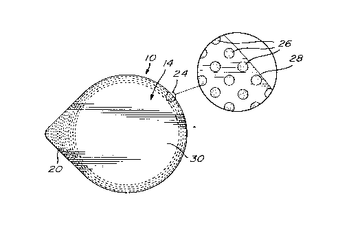
Referring to figure 1, there is shown a lid,
generally denoted 10, made in accordance with the present
nvention .
Referring also to figure 2, the lid has a top
side 12 and an underside 14 which is adapted to be
hermetically and peelably sealed to the peripheral flange
or rim 16 of a plastic container 18.
The lid has been die cut to a shape
corresponding to that of the flange 16 of the container
and may include a finger gripping portion 20 also sealed
212765~
to a corresponding extension 22 of the flange of the
container.
The present invention is concerned with
providing a pattern of thermoplastic adhesive to the
peripheral edge of the underside 14 of the lid. As can
be seen in figure 1, the pattern of adhesive consists of
an arrangement of fine particles 26 forming bosses which
are separate from one another thus leaving a gap
therebetween to thereby provide direct or indirect air
circulation from the peripheral edge 28 of the lid to the
unembossed region 30 in the central region of the
underside of the lid.
Referring to figure 3, there is shown a lid
magazine 32 in which are stacked a plurality of
superposed lids, and a lid destacking device, generally
denoted 34, which includes an arm 36 equipped with a lid
contacting and retrieving element 38; this arm removes
the lids from the bottom of the magazine 32 and moves (as
indicated by arrow 40) to the position shown in dotted
lines where the lid is ready to be deposited over the
mouth of a container.
The representation of figure 4 shows in an
exaggerated ways the superposition of the lids to
indicate that an air gap exists between adjacent bosses
so that, as a lid is retrieved by the device 34, the
212765
usual surface adherence between two contacting lids of
thermoplastic material, such as polyethylene, is
prevented so that only one lid is retrieved at a time.
Figure 5 is a schematic representation of the
method of making the bosses on the underside of a lid.
From a reel 42, a strip 44 of a thin sheet of plastics
material is passed by a first series of rollers 46, 48,
50 and 52 and then between a pair of vertically disposed
rollers, including an upper pressure roller 54 and an
engraving lower roller 56. The latter roller has a major
portion thereof submerged in a bath 58 of hot melt
material, such as a copolymer of ethylene and vinyl
acetate (EVA), contained in a reservoir 60. The hot melt
material collected by roller 56 is in part removed by a
scraper 62 as further explained hereinbelow.
Referring to figure 6, the cylindrical surface
of roller 56 is configured with an engraved areas 56a and
a plurality of non engraved areas 56b. The area of these
areas 56b is circular correspond to that of the non
embossed area 30 on the underside of the lid (see figure
1) .
As can be seen in figure 7, the engraved area
56a consists of a series of a plurality of recesses 64,
which may have various shapes, the configuration and
2127 ~5~
-- 8
disposition of these recesses will be found on the
underside of the lid.
In bath 58, the cylindrical surface of rotating
roller 56 is covered with the hot melt adhesive.
However, scraper 62 removes the adhesive from the non
engraved surfaces 56b, thus leaving adhesive only in the
recesses 64. As the sheet 44 passes between rollers 54
and 56, the pressure on roller 54 causes the transfer of
the adhesive from the recesses 64 onto the film, the
lower face of which now has a configuration resembling
that of the outer surface of roller 56. As illustrated
in figure 5, the modified film 44' is then past onto a
series of rollers (not shown) allowing the chilling of
the bosses, then printing, if needed, on the top side of
the film and to a die cutting operation which cuts the
film into a series of lids having, for example, a
configuration such as that shown in figure 1. These
various steps are not illustrated as they are well known
in the art.
Although the invention has been described above
in relation to a specific form, it will be evident to a
person skilled in the art that it may be modified and
refined in various ways. For example, the pattern of
bosses may have various configurations; the only
requirement is that the bosses must not be continuous so
as to block air circulation from the edge of the lid to
_ 9 2 12765 0
the central region thereof. It is therefore wished to
have it understood that the present invention should not
be limited in interpretation, except by the terms of the
following claims.