Language selection

Search

Patent 2127723 Summary

Third-party information liability

Some of the information on this Web page has been provided by external sources. The Government of Canada is not responsible for the accuracy, reliability or currency of the information supplied by external sources. Users wishing to rely upon this information should consult directly with the source of the information. Content provided by external sources is not subject to official languages, privacy and accessibility requirements.

Claims and Abstract availability

Any discrepancies in the text and image of the Claims and Abstract are due to differing posting times. Text of the Claims and Abstract are posted:

  • At the time the application is open to public inspection;
  • At the time of issue of the patent (grant).
(12) Patent: (11) CA 2127723
(54) English Title: GRIPPING DEVICE FOR TIMBER
(54) French Title: DISPOSITIF PREHENSEUR DE GRUMES
Status: Expired and beyond the Period of Reversal
Bibliographic Data
(51) International Patent Classification (IPC):
  • A63B 27/00 (2006.01)
  • E06C 07/00 (2006.01)
(72) Inventors :
  • NICKEL, DONALD C. (Canada)
(73) Owners :
  • DONALD C. NICKEL
(71) Applicants :
  • DONALD C. NICKEL (Canada)
(74) Agent: MACRAE & CO.
(74) Associate agent:
(45) Issued: 2003-12-16
(22) Filed Date: 1994-07-05
(41) Open to Public Inspection: 1995-01-16
Examination requested: 1999-02-16
Availability of licence: N/A
Dedicated to the Public: N/A
(25) Language of filing: English

Patent Cooperation Treaty (PCT): No

(30) Application Priority Data:
Application No. Country/Territory Date
08/092,053 (United States of America) 1993-07-15
08/243,924 (United States of America) 1994-05-17

Abstracts

English Abstract


A gripping device is provided for use with vertical or near vertical
timbers on building sites, especially with 2" x 4", 2" x 6", or 2" x 8"
planks, and
which allows such timbers to be used with a series of the devices forming
steps of
a temporary ladder. The timber may be leaning against a surface, or may be
part
of a scaffold or studs of a house. The device may be formed of a single piece
of
rod, or as a casting. 1t has a closed loop part suitable for use as a step,
and also
has a retaining part, the retaining part and loop having parallel portions
defining
an open sided recess for receiving the timber. At least one of the parallel
portions
has a set of teeth facing the other parallel portion, such that the device can
be slid
sideways on to a timber and can be pivoted down to cause the teeth to engage
the
timber and prevent further movement of the device.


Claims

Note: Claims are shown in the official language in which they were submitted.


CLAIMS:
1. A gripping device far use with a generally vertical flat-sided timber, said
device being largely
formed from a single piece of rod-like element;
wherein said rod-like element includes a closed loop part and a retaining part
extending
rearwardly of the closed loop part, said retaining part being formed by a
rearwards extension of the
closed loop part and lying in the same plane as said loop part, said loop part
having its opposite sides
both suitable for use as a step or hand bald for climbing the timber;
said retaining part and loop part having parallel portions defining an open-
sided recess for
receiving the timber, one of said parallel portions having two sets of teeth
facing the other parallel
portion, each of said sets of teeth being positioned so that a plane joining
the teeth to said other
parallel portion is angled relative to the plane occupied by the loop part and
retaining parts;
whereby said device can be engaged with the timber by having the open-sided
recess placed
an the timber with said parallel portions on opposite flat sides of the
timber, and by subsequent
pivoting of the device relative to the timber into a position in which the
timber is gripped between the
teeth of one of said sets and said other parallel portion,
and wherein said two sets of teeth are provided in a symmetrical arrangement
both above and
below said plane, and such that the device can equally be used in a first
orientation with the recess
engaged on one side of a timber and can alternatively be used in inverted
orientation with its recess
engaged on the opposite side of the timber; downwards pivoting on the loop
part tending to urge the
Mower of said sets of teeth into the timber.
2. A device according to claim 1, wherein said rod-like element is steel
reinforcing rod
characterized by ridge elements which are exposed on at least a top side of
said loop part to provide
a non-slip surface for said device; said device having its tap surface
otherwise uninterrupted by
protrusions.
6

3. A device according to claim 1, wherein said sets of teeth are formed on
opposite edges of an
angle member welded to said one parallel portion, said one parallel portion
being a rear side of said
loop part.
4. A device according to claim 1, wherein said closed loop part is essentially
rectangular.
5. A temporary ladder comprising a flat-sided timber and a series of devices
according to claim
1, said devices being engaged with the timber and spaced apart to form a
series of steps and hand
holds capable of being used for climbing the timber.
6. A gripping device for use with a generally vertical flat-sided timber, said
device being
integrally formed from a single piece of material;
wherein said device includes a closed loop part and a retaining part extending
rearwardly of
the closed loop part, said retaining part being formed by a rearwards
extension of the closed loop part
and lying in the same plane, said loop part having its opposite sides both
suitable for use as a step or
hand hold for climbing the timber;
said retaining part and loop part having parallel portions defining an open-
sided recess for
receiving the timber, one of said parallel portions having two rows of teeth
facing the other parallel
portion, said rows of teeth being positioned in a symmetrical arrangement both
above and below said
same plane, and so that planes joining the teeth to said other parallel
portion are angled relative to
said same plane;
whereby said device can be engaged with the timber by having the open-sided
recess placed
on the timber with said parallel portions on opposite flat sides of the
timber, and by subsequent
pivoting of the device relative to the timber into a position in which the
timber is gripped between one
raw of said teeth and said other parallel portion, said two rows of teeth
allowing the device to be used
with the recess engaged on one side of a timber and alternatively to be used
in inverted orientation
with its recess engaged on the other side of the timber, downwards pivoting of
the loop part tending
to urge the lower of said rows of teeth into the timber.
7

7. A device according to claim 6, which is integrally formed as a steel
casting.
8. A device according to claim 6, wherein said closed loop part is essentially
rectangular.
9. A temporary ladder comprising a flat-sided timber and a series of devices
according to claim
6, said devices being engaged with the timber and spaced apart to form a
series of steps and have
holds capable of being used for climbing the timber.
8

Description

Note: Descriptions are shown in the official language in which they were submitted.


i~:g.~~'~;~
FIELD OF THE INVENTION
The present invention provides a gripping device for use with generally
vertical flat sided timbers, and is particularly useful on building sites to
allow such
timbers, either loose or incorporated in a building or in scaffolding, to be
used as a
kind of temporary ladder.
PRIOR ART
There are known gripping or climbing devices for timber, such as
timber poles, which are attached to a workman's boots, for when he wants
repeatedly to climb up poles, for example for electrical repair work. An
example
of such a device is shown in U.S. Patent No. 3,726,360, which issued April 10,
1973
to Price et. al. Such devices are however of little use on building sites,
where a
workman spends only a short proportion of his time climbing from one location
to
another, and would not want to strap devices as shown in this prior patent to
his
boots every time he wanted to climb to another level.
SUMMARY OF THE INVENTION
By contrast with known climbing devices of the type referred to above,
the present invention provides a gripping device which does not attach to
boots,
etc., and which will normally remain in place on a vertical or near vertical
timber,
and is such that several of such devices placed one above the other can
provide a
series of steps and hand holds for workmen to move up or down from one level
to
the next. When work is finished at a particular site, the devices can easily
be
removed from the timbers and reused at another site. The devices can be used
not only with vertical building studs or scaffolding timbers, but also with a
loose
piece of timber propped up against a surface as a ladder. The devices have
uses
other than for climbing, and for example may hold a pulley or rope to a
timber.
In accordance with the invention, a gripping device for use with a
generally vertical flat-sided timber is largely formed from a single piece of
material, the device including a closed loop part and a retaining part
extending
rearwardly of the closed loop part, the retaining part being formed by a
rearwards
extension of the closed loop part and lying in the same plane. The loop part
is
suitable for use as a step or hand hold in climbing the timber. The retaining
part
and the loop part have parallel portions defining an open sided recess for
receiving the timber, and at least one of the parallel portions has a set of
teeth

facing the other parallel portion, the teeth being positioned so that a plane
joining
the teeth to the other parallel portion is angled relative to the plane
occupied by
the closed loop part. The device can be engaged with a timber by having the
open-sided recess placed on the timber with the parallel portions on opposite
sides
of tlue timber, and by subsequent pivoting of the device downwards into a
position
in which the timber is gripped between the teeth and the other parallel
portion.
The device may be formed from a single rod-like element or as a
single, integrally cast piece of metal, such as steel. The rod-like element
may be a
bar or tube, but is preferably round steel rod having ribs, which is already
available
as reinforcing rod for concrete. This type of rod has ribs which are
preferably
exposed at least on a top side of the loop to provide a non-slip surface for
the
step. Alternatively, the device may be a casting with ribs cast in place. The
step
device otherwise has its top surface uninterrupted by protrusions, and in this
sense
is different from that of U.S. Patent No. 3,726,360, in which the strap
retaining
members are in the form of protrusions which would make the device difficult
for
use as a step device.
Further in accordance with the invention, two of said sets of teeth are
provided in a symmetrical arrangement both above and below the plane of the
device, and such that the device can equally be used in a first orientation
with its
recess engaged on the one side of a timber, and can alternatively be used in
inverted orientation with its recess engaged on the opposite side of the
timber.
BRIEF DESCRIPTION OF THE DRAWINGS
The invention will further be described with reference to the preferred
embodiment shown in the accompanying drawings, in which:
Fig. 1 shows a side view of two of the step devices attached to a
vertical timber, for example as part of a scaffolding;
Fig. 2 shows a side view of a series of the step devices of this invention
mounted on a timber plank to form a ladder allowing access to a deep pit;
Fig. 3 shows a bottom view of one of the step devices, as seen on lines
3-3 of Fig. 1;
Fig. 4 shows an enlarged side view of the step device as shown on lines
4-4 of Fig. 3;
Fig. 5 shows a view similar to Fig. 3 of a modified form of the device,
2

produced as a casting;
e~~~'7'a ~~
Fig. 6 shows a side elevation of the device of Fig. S; and
Fig. 7 is a cross-sectional view on lines 7-7 of Fig. 5.
DETAILED DESCRIPTION
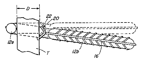
Referring to the drawings, especially Figs. 3 and 4, the gripping device
is largely formed from a single length of steel rod 12, which is bent to form
a
substantially rectangular closed loop part A, at the front, and a retaining
part E
extending rearwardly of the loop part. The terms "front" and "rear" and
similar
terms are used herein with reference to how the device is viewed when in use,
10 when part A projects towards a user. The shape of the formed rod part is
similar
to that of a right angled "6", and lies in a single plane. The loop part has a
rear
portion 12a, a first side portion 12b, a front portion 12c, a long second side
portion
12d which is welded to the end of portion 12a, and extends beyond this and
forms
the retaining part together with a right angled end part 12e. Portions 12a and
12e
are parallel, and together with the extension of side portion 12d form
opposite
sides of a open-sided recess capable of receiving a timber T which is
preferably 2"
x4",2"x6"or2"x8"plank.
The steel rod 12 may be well known reinforcing rod (also known as re-
rod) used for concrete structures. For adequate rigidity, this should have a
diameter of more than 1/2" and preferably about 5/8" or 15 mm. This type of
rod
is made with transverse ridges 15 which extend at an angle of about 60°
to the axis
of the rod between longitudinal ribs 16 on opposite sides of the rod. For this
invention the rod is preferably bent so that the longitudinal ribs 16 are on
the
inside and outside of the loop, so that the ridges are fully exposed on the
top and
bottom of the loop to provide a non-slip surface when the device is used as a
step.
Preferably, the loop part is made large enough or small enough that it will
not trap
a worker's boot.
The rear rod portion 12a carries a toothed angle member 20 securely
welded to it, this member 20 having two mutually perpendicular flanges 22
extending at about 45° away from the central plane of part 12a towards
the recess.
Each flange 22 has a series of teeth 22a along its outer edge, capable of
engagement with timber T inserted into the recess. As seen in Fig. 4, the
dimension D between the ends of teeth 22a and the nearest surface of portion
12e,
3

in the plane of the rod element, is about 1-1/2" and is chosen to allow the
device
to slidingly engage with a timber T with little or no interference, when the
plane of
the step device is perpendicular to the timber. The device can then be pivoted
down, as shown in full lines in Fig. 4, and in Figs. 1 and 2, until the lower
set of
teeth firmly engage in the timber. On vertical timber the steps devices slope
downwardly, but the ridges 15 provide a suitable non-slip surface for a
workman's
boot. The steps can be horizonal on a sloping piece of timber as shown in Fig.
2.
The toothed angled members 20 for these devices can be produced
from flat plate steel, by cutting series of parallel rows of apertures the
sides of
which define the surfaces S between the teeth, and then separating strips from
the
plate by severing the narrow connecting parts which correspond to the outer
ends
of the teeth. This produces flat plates having teeth along opposite edges,
which
can then be bent at 90° along a centre line to produce the member 20.
It will be appreciated that a bundle of these devices can be taken by a
workman to a building site, and applied to vertical or near vertical timbers,
which
may be building studs or scaffolding timbers, and the devices provide both
steps
and hand holds for easy climbing between floors. This is especially useful in
house
construction before installation of a staircase. The symmetrical nature of the
devices allows them to be used on either side, i.e. the left hand side or the
right
hand side, of a timber plank, and preferably the devices are installed
alternately on
opposite sides of the timber, as indicated in Figs. 1 and 2. Fig. 2 shows a
kind of
ladder made by combining a series of the devices with a single piece of
timber.
The timber for such ladder is preferably fairly wide, e.g. 2" x 8", to give
reasonable
stability in climbing.
In addition, the gripping devices can be used for other purposes when
it is necessary to provide a securement of an element to a piece of timber.
For
example, the devices can be used to secure a pulley or the end of a rope to a
vertical or horizontal timber.
Figs. 5 to 7 show a modified form of the device which is integrally
formed from steel, as a casting.
The basic form of the device is the same as that of the first
embodiment, and incudes a closed, essentially rectangular, loop part having a
rear
portion 112a, a first side portion Il2b, a front portion 112c, a long second
side
4

portion 112d which is joined to the end of portion 1121, and which extends
beyond
this to form the retaining part together with right angled end part 112e. As
before, portions 112a and 112e form sides of an open parallel sided recess for
receiving a piece of timber.
The cross-sectional shape of parts 112b, 112c, 112d, and 112e is shown
in Fig. 7. Each of these parts has flat inner and outer sides, and channels
116 in
the upper and lower surfaces. 'This shape provides weight saving combined with
adequate strength, and the ribs on each side of channel 116 provide an anti-
slip
feature. A central area of portion 112a, shown at 120, may be flattened to
receive
a trademark.
As in the first embodiment, portion 112a is provided with two rows of
teeth 122 disposed above and below the plane of the device and which face
inwardly of the recess between portions 112a and 112e. The teeth are provided
by
flat lands between U-shaped recesses cast into the inner side of portion 112a.
These flat lands can co-operate with curved rear faces 122a of the teeth to
provide
sharp edges at the upper and lower extremities of the lands. For most
purposes,
sufficiently sharp teeth for engagement with timber can be produced merely by
the
casting process, but if desired these can be sharpened by machining the rear
faces
122a. As in the first embodiment, the symmetrical arrangement of the rows of
teeth above and below the plane of the device allows this to be used with
either of
its faces oriented upwardly for engagement with either a left or a right side
of a
timber.
5

Representative Drawing
A single figure which represents the drawing illustrating the invention.
Administrative Status

2024-08-01:As part of the Next Generation Patents (NGP) transition, the Canadian Patents Database (CPD) now contains a more detailed Event History, which replicates the Event Log of our new back-office solution.

Please note that "Inactive:" events refers to events no longer in use in our new back-office solution.

For a clearer understanding of the status of the application/patent presented on this page, the site Disclaimer , as well as the definitions for Patent , Event History , Maintenance Fee  and Payment History  should be consulted.

Event History

Description Date
Time Limit for Reversal Expired 2006-07-05
Inactive: Adhoc Request Documented 2005-09-19
Letter Sent 2005-07-05
Grant by Issuance 2003-12-16
Inactive: Cover page published 2003-12-15
Inactive: Final fee received 2003-09-18
Pre-grant 2003-09-18
Notice of Allowance is Issued 2003-08-15
Letter Sent 2003-08-15
Notice of Allowance is Issued 2003-08-15
Inactive: Approved for allowance (AFA) 2003-07-30
Amendment Received - Voluntary Amendment 2003-07-04
Inactive: S.30(2) Rules - Examiner requisition 2003-01-06
Letter Sent 2002-07-24
Reinstatement Requirements Deemed Compliant for All Abandonment Reasons 2002-07-11
Deemed Abandoned - Failure to Respond to Maintenance Fee Notice 2002-07-05
Inactive: Application prosecuted on TS as of Log entry date 1999-03-03
Inactive: RFE acknowledged - Prior art enquiry 1999-03-03
Inactive: Status info is complete as of Log entry date 1999-03-03
Request for Examination Requirements Determined Compliant 1999-02-16
All Requirements for Examination Determined Compliant 1999-02-16
Letter Sent 1999-02-08
Reinstatement Requirements Deemed Compliant for All Abandonment Reasons 1999-01-28
Deemed Abandoned - Failure to Respond to Maintenance Fee Notice 1998-07-06
Application Published (Open to Public Inspection) 1995-01-16

Abandonment History

Abandonment Date Reason Reinstatement Date
2002-07-05
1998-07-06

Maintenance Fee

The last payment was received on 2003-04-17

Note : If the full payment has not been received on or before the date indicated, a further fee may be required which may be one of the following

  • the reinstatement fee;
  • the late payment fee; or
  • additional fee to reverse deemed expiry.

Patent fees are adjusted on the 1st of January every year. The amounts above are the current amounts if received by December 31 of the current year.
Please refer to the CIPO Patent Fees web page to see all current fee amounts.

Fee History

Fee Type Anniversary Year Due Date Paid Date
MF (application, 4th anniv.) - small 04 1998-07-06 1999-01-28
Reinstatement 1999-01-28
Request for examination - small 1999-02-16
MF (application, 5th anniv.) - small 05 1999-07-05 1999-06-17
MF (application, 6th anniv.) - small 06 2000-07-05 2000-06-29
MF (application, 7th anniv.) - small 07 2001-07-05 2001-05-24
Reinstatement 2002-07-11
MF (application, 8th anniv.) - small 08 2002-07-05 2002-07-11
MF (application, 9th anniv.) - small 09 2003-07-07 2003-04-17
Final fee - small 2003-09-18
MF (patent, 10th anniv.) - small 2004-07-05 2004-05-21
Owners on Record

Note: Records showing the ownership history in alphabetical order.

Current Owners on Record
DONALD C. NICKEL
Past Owners on Record
None
Past Owners that do not appear in the "Owners on Record" listing will appear in other documentation within the application.
Documents

To view selected files, please enter reCAPTCHA code :


To view images, click a link in the Document Description column. To download the documents, select one or more checkboxes in the first column and then click the "Download Selected in PDF format (Zip Archive)" or the "Download Selected as Single PDF" button.

List of published and non-published patent-specific documents on the CPD .

If you have any difficulty accessing content, you can call the Client Service Centre at 1-866-997-1936 or send them an e-mail at CIPO Client Service Centre.


Document
Description 
Date
(yyyy-mm-dd) 
Number of pages   Size of Image (KB) 
Representative drawing 1998-06-25 1 10
Claims 2003-07-03 3 113
Representative drawing 2003-07-30 1 11
Description 1995-06-09 5 218
Drawings 1995-06-09 3 67
Abstract 1995-06-09 1 18
Claims 1995-06-09 3 118
Courtesy - Abandonment Letter (Maintenance Fee) 1998-08-02 1 189
Notice of Reinstatement 1999-02-07 1 170
Acknowledgement of Request for Examination 1999-03-02 1 173
Courtesy - Abandonment Letter (Maintenance Fee) 2002-07-23 1 183
Notice of Reinstatement 2002-07-23 1 170
Commissioner's Notice - Application Found Allowable 2003-08-14 1 160
Maintenance Fee Notice 2005-08-29 1 172
Correspondence 2003-09-17 1 29
Fees 1999-01-27 1 39
Fees 2002-07-10 1 37
Fees 1996-08-06 4 225
Correspondence 2005-09-28 2 115
Fees 1997-04-29 1 45
Fees 1996-10-16 1 39