Note: Descriptions are shown in the official language in which they were submitted.
2127984
E~ol~ing Arranqement For Cans
This invention relates to arrangements for
holding a pLurality of cans.
Multipacks of cans are well known for drinks
and foodstuffs. Cans of drink are often sold in
multipacks utilising a plastic ring having,a number of
apertures for receiving a corresponding number of
cans. This number is often four or six. It is
however desirable ~o cease using plastic in such
multipacks.
Attempts have been made to produce
satisfa^tory paper~oard alternatives to the plastic
ring but the alternatives tend to be of an all
encompassing nature or sleeve-like.
According to a first aspect of the present
; 15 invention there is provided a packaqe for a plurality
of cans, said packaye comprising first means whi~h for
e~ach can has a top section and integral means for
gripping each can below the top rim, said gripping
means being arranged`in an array s~uch that each can is
~ in substantially touching relation with all
immedi~tely adjacent cans t and second means having a
top panel for attachment to said first means and side
paneL means ~or extending all around the periphery of
the~ pLurality ~of cans, said side panel ~eans
comprlsing one or more side panels hinged downwardly
re~lative to said to~ panel, one or more of said side
panels in contact with the cans and having one or more
portions extending around one or more of said cans
fox attachment to at least one of said side panels.
30 ~ Pref erably said first and second means are
made from paperboard. The first means is ideally made
from a single piece of paperboard which constitutes
all said top sections and gripping means.
Conveniently each gripping means comprises a pair of
~spaced arcuate cuts between which the top of a can is
~:
:
AMENDED SHEET
21279g4
disposed, the paperboard adjacent t~e cuts being
pressed down under the rim of the can so as to grip
the can below the rim.
In preferred arrangements the array may be
generally rectangular, for exampLe a 2x2, 2x3 or 2x4
array of cans, by vir~ue of the gripping~eans being
arranged in a suitable array.
The toP panel is preferably generally
rectangular in plan view and four side Danels are
provided. In one arrangement an opposite pair of side
panels, each has a pair of oppositely extending
extensions whic~ are, in use, bent ~round ~he adjacent
corner can of the rectangular array such that each
side panel of the other pair of opoosi~e side panels
is attached to two extensions, one from e~ch of the
first pair of side walls.
Ideally the top panel of the second means
incorporates one or more formation to facilitate the
picking up of the package. This formation ma~
comprise one or more holes. The handle may als~ be an
i~tegrally formed strap or even a handle/strap
assembly secured ln said top panel.
- Preferably the top panel is adhesively secured
to all 'he top sect~ions of the first means and the
side~ panels are~adhesively secured to each other. It
is possible, however, that one or both of these
attachments could~be by interlocking formations on the
two~parts.
According to a second aspect there is provided
A pair of blanks for holding a plurality of cans, the
3~ ~first bl~nk having a number of pairs of spaced,
oppositeLy disposed arcuate cuts for receiving a
corresponding number of cans so as, in use, to hold
thé cans in an array such that each can is in
substantiaLly touching relation with all immediately
A~ 3 SilE~
.
2127984
-2a-
adjacent cans and the second blank provides a top
panel and one or more side panel means hingedly
connected thereto for extending all around ~he
periphery of the plurality of cans, one or more of
which side panPl means comprises one or m~'~ extension
portions which, in use, extend around one or more of
said cans in contac~ therewith for attachment to one
of said side panels.
Preferably the pairs of cuts are arranged in a
rectangular array so as in use to secure a rectangular
~ ~ .
::
c O
. .
.. .
''
J ; i L _:
;',
~093/149~2 2 ~ 2 7 9 ~ 4 PQ/GBg3/00141
array of cans. A preferred feature is that the two
ends of each cut are located on a straight hinge line
and the ends of more than one cut may be on any one
hinge line. Between pairs of cuts is a reverse hinge
line parallel to said straight hinge line, f~r enabling
in use the cans to be disposed in touching relation to
each other.
Preferably ~he top panel is generally
rectangular and there are four corresponding side
panels, each side panel of one opposite ~air of side
panels having lateral extensions at both sides. The
other pair of side panels may incorporate a sub-panel
hingedly connected to the remainder along a parallel
hinge line.
Embodiments of the invention will now be
described in more detail. The description makes
reference to the accompanying diagrammatic drawings in
which:
~ igure 1 shows a perspective view of a
complete package according to the present inven~ion,
Figure 2 shows a plan view of a first blank
used in the production of the p~ckage of figure 1,
Figure 3 shows a plan view of a second blank
used in the production of the package of figure 1,
igure 4 shows the stage by stage manufacture
of the figure 1 package,
Figure 5 shows an alternative second blank for
use in a package similar to that shown in figure 1.
Figure 6 shows a further alternati~e second
blank for use in a package according to the present
vention, and
igure 7 shows a perspective view of a
complete package made using a further blank.
Figures 1 ~o 5 show packages and blanks
~; relating to the manufacture of a 2x2 can multipack.
It will be readilv a~preciated by the skilled reader
WO93/14992 21 2 7 9 8 ~ PCT/GB93/0014~
-4-
that the blanks and techniques could be readily
adapted to all forms of can multipacks be they simple,
such as 2xl, 2x2, 2x3, 2x4, 2x5, 2x6, 3x3, 3x4 or more
complex such as hexagonal arrangements of cans, 4-3-4
arrays or similar. Indeed figures 6 and 7~relate to a
2x3 and 2x2 arrays respectively.
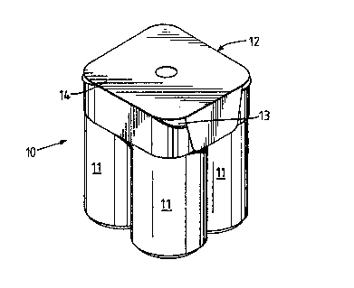
Figure 1 shows a multipack 10 for four cans 11
in a 2x2 array. The cans are tightly packed in the
square formation and the sides of the cans 11 are in
substantially touching relation to adjacent cans 11.
The packaging 12 is made of paperboard and is forme~
from two blanks 13, 14. The inner blank 13 is only
just visible unlike the outer blank 14. As a result
the outer blank provides considerable space for
product information, printed advertisements, logos,
promotions, information or competitions and the iike.
The inner blank 13 is shown in detail in
figurQ 2. The blank 13 is generally square with
rounded corners. The blank is formed with a number of
: :
arcu~te cu~s 15 which are arranged in pairs. Each
~pair of cuts 15 defines a top section 16 between them,
which top section 16, in use, is located on the top of
the rim of i~s associated can. Hinge lines 17 extend
betweén the ends of adjacent cuts 15 to form gripping
pa~els 18~and these hinge lines may be creased and/or
perforated. To fix the blank 13 on to the set of four
cans 11, the cans are disposed below the respective
~ top sections I6 and the gripping panels 18 are Dr~ssed
;~ down so that the gripping panels 18 adjacen the
arcuate cuts 15 engage below the rims of the cans 11.
Fur*her hinge lines 19 depend from the cuts 1~ to
improve the grip of the panels 18 by modifying the
bending of the gripping panels 18 so as to conform
more closely to the shape of the cans.
A reverse hing~ line 20 is formed midway
betweer. ~he adja~ent rGWS and in manurac~ure ~ ?-~
wo 93/149~2 ~ ~ ~ 7 9 8 4 PCT/~B93/00141
can depress the blank 13 along this hinge line 20 and
the two rows of cans will be brought closely together,
ideally in tou~hing relationship~
The attachment of the inner blank to the cans
is shown in stage one of figure 4. The ~lough 21 is
visible as it ac~ivates the hinge line 2~.
Stage 2 of manufacture applies glue to the top
faces of all the top sections 16 of the blank 13. The
ideal positions of the glue line 22 are shown in
figure 2. A line 22 is provided adjacen~ each hinge
line 17 to give optimum strength to the resulting
package.
Figure 3 shows the outer blank 14. The blank
14 has a top panel 23 incorporating a hole 24 to
facilitate lifting of the assembled multipack l0. The
;~ 15 top panel 23 is generally square with rounded corners
¦~ and has side panels 25, 26, 27, 28 hingedly connected
thereto along fold lines 2~, 30, 31, 32. Opposite
side panels 25, 27 haye lateral extensions 33, 34, 35,
3~ depending therefrom.
. 20 In us~e the blank is placed centrally on and
; : pressed on to the inner blank 13/cans ll combination
ana is stuck thereto by the adhesive lines 22. This
lS shown in stage 3 of figure 4. The side panels 25,
27 having extensions are folded down along fold lines
29, 31~ respectively as shown in stage 4 of fi~ure 4.
The extensions 33, 34, 35, 36 are then folded around
the adjacent cans as shown in stage 5 of figure 4.
~Adhesive is then applied to the undersides of side
~: panels 26, 28 as shown in stage 6 of figure 4 and they
3 are then bent down along hinge lines 30, 32
:: : respectively as shown in stage 7 of figure 4. The
side panels 26J 28 are pressed inwards and thus become
adhesively secured to extensions 33, 34, 35, 36 of the
o~her si~e panels 25, 27. Figure 3 shows in dotted
lines th~ best areas 37 for adhesive to be applied to
J~:
!}
.~
~.~
i'
W093/l4992 21 2 7 9 8 4 -6- PCT/GB93/0014 ,
panels 26, 28.
The result is a strong, simple multipack
arrangemen~ 10 formed from paperboard. The multipack
retains its rigidity regardless of the manner it is
picked up, a feature not present in multipacks using
existing plastic rings~ This rigidity is advantageous
both for consumers and retailers and there is a strong
resistance to cans becoming dislodged from the
multipack.
The alternative blank 114 shown in figure 5 is
almost identical to that shown in figure 3 and like
~ parts have been given like reference numerals The
¦ only difference is that the side panels 26, 28
~ incorporate further fold lines 38, 29 parallel to ~old
I lines 30, 32 so as to provide small angled panels 40,
1 15 41. Such a blank 114 conforms more closely to modern
day beverage cans which have an inwardly bevelied side
wall area just below the top rim.
Referring to figure 6 there is shown a further
blank~ 214 which is or use in a 2x3 array of cans.
The blank 214 is really just an extended versio~ of
blanks 14 and 114 for use with a similarly extended
inner blank 13. The only significant difference is
he provislon;o~ slits 201 for receiving the rims of
th~e cans. The slits 201 provide an aesthetic
alternative to~the~ straight folded perpendicular side
panels 26, 28 ~of the previously described
rrangements.~
In figure 7 there~is shown a package made from
a blank 314 which is a 2x2 version of the blank 214
shown in flgure~6. The blanX 314 also provides slits
201 for l~ocating the can rims.
It is also possible to bring together two or
more inner blanks, connected to cans, and attach using
adhesive a suitably shaped upper blank covering all
the inner blanks. This arrangement is not shown, but
is simple ~c ~nderstand. F~r example, 2x (2x3) or 2x
-7- 2127~8~
WO93/14992 PCT/GB93/00141
or 4x (2x2) arrays can b~ formed USll.
shaped upper blanks extending ov~ ~ è~o~'e~Sarrays.
It will of course be ap ~ ~ t~at the side
panels may extend any distance down the side of the
cans ll depending on the particular requirements of
the manufacturer. For example, if a promotion is
being run then one side panel may extend a long way
down the cans compared to the other side ~ els.
Also the precise positioning of the extensions
is a matter of design choice. For example, they could
be longer and extend further around the pack or they
may be repositioned so that each side panel has an
extensionO Also some side panels may be eliminated in
certain arrangements. For example, in its most basic
form one side panel having one long extensio~ is
possible, the extension extending around the entire
pack and being adhesively secured to itself. Whilst
this arrangement may not provide ideal strength it is
very sim~l~ and strength/rigidity may not always be a
: necessity of the~manufacturer.
As previously stated the precise gluing
positions are a matter of choice as are the precise
shapes of the panels.
: As an alternative the panels to be adhesively
secured together could instead be connected by
suita~le interlock1ng means. Many suitable
interlockin~ formations are known in the industry f or
securing two pieces of paperboard together.
The grain of the paperboard can also be a
factQr in the strength of the package. For best
results the grain of the paperboard extends in the
direction perpendicular to the fold line 20 on the
3 first blank 13 and perpendicular to the fold lines 30,
:
32 on the second blank 14. The yrain direction is not
however essential to the basic operation of the
packaye.
It will be appreciated that the precise
adhesive Positions described are only examples of
suitable positionsJ-~an!d may therefore be variec.
3 ~ - .