Note: Descriptions are shown in the official language in which they were submitted.
21 280 0 8
1
SELF-CLEANING,/UNBLOCKING SPRAY NOZZLE
Spray nozzles are well known devices for producing
controlled sprays of liquids for applications such as paint
spraying, crop spraying to dispense fertilizer and
insecticide, industrial washing and chemical treatment.
For most applications it is essential for a spray nozzle to
produce an evenly distributed spray of uniform liquid
particles in a predetermined spray pattern.
In most cases the spray pattern consists of fine
droplets created by forcing liquid into the nozzle through
a large orifice and out of the nozzle through a smaller
discharge orifice or plurality of smaller discharge
orifices. The finer the droplets required, the smaller the
size of the discharge orifice. The discharge orifices in
known spray nozzles are usually outlet openings of a static
nature and preset dimensions, e.g. holes drilled or moulded
into the ends of nozzle members. The outlet openings or
holes, being of small size, have a tendency to block
frequently with particles of dirt, crystals and other
matter present in the liquid or the spraying equipment.
Conventional methods of removing trapped particles to
clean the spray nozzle and allow liquid to flow properly
are very labour intensive. The spray nozzles need to be
removed frequently from the spraying equipment and--cleaned
out by hand. Often there are large numbers of spray
nozzles and they can be in difficult to access locations.
The spray nozzles can also be contaminated with toxic or
corrosive liquid if that is the nature of the material
passing through the nozzle. Whilst this cleaning process
is undertaken, production cannot continue which is
extremely costly.
In order to reduce the need for frequent
cleaning of the nozzles, British Patent GB0987723
(published 31 March 1965, Graham-Enoch Manufacturing
Co. Ltd.) discloses a spray nozzle comprising a
hollow member having an outlet opening at its
21 280 0 8
2
front end, and a movable device within the hollow member.
The movable device comprises a plurality of separable
segmental parts, and the device can be moved by fluid
pressure to move the segmental parts towards each other to
create a spray discharge orifice at the front end of the
nozzle.
The segmental parts can separate when relieved of
fluid pressure, so that discharge orifice can be opened-up
for releasing particles so as to tend to prevent collection
of matter which could block the orifice. However, this
known spray nozzle has the disadvantage that when
orientated so that the open end is lowermost, the segmental
parts remain together and fail to release such matter.
There is disclosed in European Patent Application EP
0482369A (published 29 April 1992, H.IKEUCHI Co. Ltd.), a
nozzle in which the rear ends of the separable parts have
radially outwardly projecting flanges which are engaged by
a rear end of a helical compression spring, located in an
annular space between the movable device and the hollow
member, to thrust the device rearwards away from the open
front end of the hollow member. To prevent fluid by-
passing the device (by flowing through this annular space),
the flanged rear ends carry a packing ring which seals
against the internal surface of the hollow member.
Additionally, the rear end part of the hollow member is
fitted internally with a retaining ring to retain the
spring, packing ring and separable parts within the hollow
member. In order to force such separable parts to separate
when fluid pressure is removed from the nozzle, surfaces of
said flanges are inclined so that the spring acts thereon
in an attempt to urge apart the front ends of the separable
parts, to try to cause the orifice to open when the device
is moved rearwards to abut the retaining ring.
The nozzle of EP0482369A gives rise to more problems
_. WO 94/13409 3 G 1 2 8 0 0 ~T/GB93/02475
than it solves. For example spring acts primarily in the
axial (front to rear) direction, and thus the packing ring
is necessary to ensure that the fluid pressure generates
enough force on the device to overcome the thrust of the
spring, but a consequence is that (upon the fluid supply
being halted) when the device moves rearwards the volume of
said annular space increases, sucking in air and/or fluid
back into the space at the same time as the separable parts
are being separated, with the resultant probability that
clogging matter will be drawn into the annular space.
Presence of such matter in the annular space, and
especially in the slight gap between the flanges and the
hollow member, can cause the nozzle to malfunction.
However, the main problem inherent in said nozzle is
that it is complex, expensive to make and designed to be
replaced as a pre-assembled unit. It is clearly not
designed to be dismantled easily for on-site cleaning and
would be even more difficult or nearly impossible to re-
assemble without renewing the rings, thus requiring the
user to carry on site stocks of spare nozzles for every
spray variant, flow rate and etc type of nozzle employed.
The present invention accepts that some blockages or
malfunctions are probably inevitable even with nozzles
which are designed to be self-cleaning, and seeks to avoid
the problems of manufacturing complexity and spare parts
costs.
In order to avoid or reduce said problems in respect
of a spray nozzle of a kind generally comprising a hollow
member having an outlet opening therein at the front of the
spray nozzle, a movable device disposed within the nozzle
and rearwardly biased to a normal position in which the
outlet opening is minimally restricted or is unrestricted
by the movable device, wherein the movable device is
movable by fluid pressure from the normal position in a
forwards direction towards the outlet opening to obstruct
WO 94/13409 ~ ~ 4 PCT/GB93/02475~
the flow to the outlet opening and to cause relative
movement between separable parts of the movable device to
create a spray discharge orifice, smaller than the outlet,
within or proximal to the outlet opening; the present
invention is characterised in that the operationally
movable parts of the spray nozzle for forming the discharge
orifice and providing said bias are all contained within or
incorporated into the movable device.
Thus, the movable device can be removed as a unit to
facilitate on-site servicing of the spray nozzle.
In order to further avoid said problems and to reduce
the risk of malfunction the present invention further
provides a spray nozzle of said kind characterised in that
the hollow member has provided therein a sealing abutment
surface adjacent the outlet opening, and the separable
parts have sealing surfaces on their front ends to engage
the abutment surfaces to provide a seal in the operative
position of the movable device to prevent fluid by-passing
the discharge orifice or orifices.
Thus, the remainder of the movable device to the rear
of said seal can be a clearance fit in the nozzle, for ease
of removal of the device and to minimise friction and risk
of matter impeding movement of the movable device.
In preferred embodiments, a nozzle of said kind is
characterised according to the present invention in that
transverse biasing means is provided in or by the movable
device to urge said separable parts to separate and react
against an internal surface of the spray nozzle to provide
said rearwards to bias indirectly.
Preferably:-
(a) said internal surface is part conical, converges
towards the outlet opening and is inclined to the
WO 94/13409 '~ 8 O O 8 PCTIGB93/02475
axis of the nozzle at an angle within the range of
20° to 40°, preferably 25 to 35°;
(b) the transverse biasing means comprises a resilient
member accommodated inside the movable device between
said separable parts;
(c) said movable device or said resilient member is
shaped to impart rotational motion to fluid passing
through the movable device.
Hy arranging the biasing means to act directly in the
separating direction on the separable parts of the device,
reliable separation is ensured; and by providing the
biasing means in the movable device all the above mentioned
problems associated with the known helical springs, spring
receiving annular spaces, packing rings and retaining rings
are avoided.
In known spray nozzles the separable parts are
individual elements which are discrete from each other, and
can be moved to abut in the operative position of the
device. In order to further reduce said problems and the
cost of the device, said separable parts are preferably
parts of a single body which can flex to permit relative
movement between said separable parts of the body.
In accordance with the present invention, some
preferred embodiments of nozzle of said kind are
characterised in that the movable device comprises a body
incorporating said separable parts, and in that the
flexible body is at least partially resilient, and serves
to provide said rearwards bias by urging the separable
parts away from each other to react against an internal
surface of the spray nozzle.
The integration of the biasing means and the
separable parts into a single body makes the spray nozzle
pCT/GB93/02475
O 94113409
6
extremely inexpensive, resistant to malfunction and easy to
service; and furthermore avoids all the well known
problems inherent in metal coil springs, such as corrosion,
breakage and malfunction, to which such springs are
particularly liable when used in a corrosive or damp
environment.
Furthermore, simple exchange of bodies can be
employed to give a change of spray characteristics, without
having to change the other parts of the spray nozzles. For
example, it is known to fit a waned insert into an ordinary
static non-self-clearing spray nozzle, in order to impart
rotational momentum to the fluid in the nozzle, but in EP
0482369A the separable parts occupy the space required for
such a waned insert.
In order to solve this additional problem the present
invention further provides a spray nozzle of said kind
which is characterised in that the movable device is hollow
and has disposed therein flow guiding means, such as vane
surfaces or vane extensions, to impart rotary motion to
fluid passed through the movable device.
The periphery of the discharge orifice may be wholly
defined by nozzle surfaces on the movable device so as to
be discrete from the periphery of the outlet opening; or
the periphery of the discharge orifice may be only
partially defined by such discrete nozzle surfaces so as to
meet the periphery of the outlet opening so that part or
parts of the surface of the hollow member defining the
outlet opening serve as a further nozzle surface or
surfaces to define part or parts of the discharge orifice.
The nozzle surfaces may be shaped to create a
plurality of the discharge orifices. The flow cross
sectional area of the discharge orifice or orifices is
preferably less than half, e.g. 0.01 to 0.1, of that of the
outlet opening.
_ _ _
WO 94/13409 ~ ~ ~ ~ PCTIGB93I02475
In some systems employing several nozzles, the rate
of fluid supply may be insufficient to generate the minimum
pressure required to move the movable devices whilst all
the devices are in the normal positions, even though the
Working flow rate is being supplied. To avoid problems of
actuation of the movable devices, the flexible body
preferably serves as a combined piston and flow restrictor
in its normal position in the spray nozzle. In a preferred
form, the integral parts are connected by a head which
serves as the piston, which head is shaped to provide a
restricted fluid flow path having a flow cross-sectional
area greater than the flow cross-sectional area of the
created spray discharge orifice or orifices. The flow path
may be defined between the head and the internal surface of
the nozzle, but is preferably primarily provided by a port
in the head.
In order to shut off the supply of liquid to known
nozzles when the supply pressure falls below a
predetermined minimum pressure, e.g. in order to reduce
"dribbling" from nozzles, it is known to provide pressure
sensitive shut off or check valves immediately upstream of
each of the nozzles or to incorporate such a valve into a
combined valve and nozzle assembly. Again, the
aforementioned further problems are involved together with
problems of reliability and blockage of the valves.
In order to reduce such problems, the movable device
in the normal position preferably serves to block flow
through the interior of the spray nozzle. In a preferred
embodiment the head cooperates with a static member to
close the port in the head whilst leaving part of the
pressure supply side face of the head exposed to any
pressure supplied to the nozzle.
The static member may be employed to restrict the
port, and be arranged, e.g. tapered, so that said
restriction reduces progressively with the distance moved
WO 94/13409 Q ~ g 8 PCT/GB93/02475_
by the movable device from the normal position.
The static member may serve as a pintle which extends
through the part and provides a flow modifying surface or
surfaces within the movable device, e.g. to impart rotation
to said flow.
The invention further includes and provides a spray
nozzle of said kind characterised in that the movable
device is hollow and in the normal position cooperates with
a static member in the nozzle to serve as a valve closing a
flow path into the movable device.
The hollow member is preferably a cap releasably
1~ secured to an inlet body, and separable from the body to
provide access for removal or insertion of the movable
device. The cap may incorporate a spray deflector axially
offset from the outlet opening, on which a spray from the
discharge nozzle can impinge.
The invention can be utilised for retro-
application to some forms of known spray nozzles, and
accordingly the present invention provides a movable
device, insertable into a spray nozzle having a removable
cap apertured to provide an outlet opening, which device
comprises separable nozzle surfaces which can be brought
into mutual proximity, against a bias in the movable
device, to create a spray discharge orifice.
The nozzle surfaces may be configured to form a
discharge orifice of any suitable geometric configuration.
The nozzle surfaces may be provided on tips of the
separable parts, which tips.may be of materials the same as
or different from the remainder of the separable parts,
e.g. metal or ceramic tips on plastics bodies or separable
parts.
WO 94/13409 9 ' ~ ~ ~ ~ ~ ~ ~ PCT~GB93/02475
The movable device is preferably a moulding of
thermoplastics material. Preferably, the moulding
comprises at least two arms joined to a central portion by
integral flexible hinges. In preferred embodiments the
arms terminate in free end portions shaped to provide
surfaces for forming the discharge orifice and further
surfaces for sliding engagement with said internal surface
of the spray nozzle.
The invention will be described further, by way of
example, with reference to the accompanying diagrammatic
drawings, wherein:-
FIGURE 1 shows an axial cross-section through a spray
nozzle of the invention incorporating a first form of
movable device of the invention in an "operative" position
adopted when spraying;
FIGURE 2 shows an axial cross-section through part of the
spray nozzle with the movable device in a "normal"
position;
FIGURE 3 shows the first form of movable device of the
invention in plan in an "as moulded" condition;
FIGURE 4 shows an axial section through a modified static
member and part of the movable device for use in the spray
nozzle;
FIGURE 5 shows a second form of the movable device in plan
in an "as moulded" condition;
FIGURE 6 shows a cross section through a further modified
form of the movable device;
FIGURES 7, 8 and 9 show front end views of variations of
the nozzle providing different spray patterns;
WO 94113409 2 - PCT/GB93/02475
FIGURE 10 is an axial sectional view through a first part
of a further modified form of the nozzle;
FIGURE 11 is a front end view of the device on its own in
5 the operative condition with the cap shown in FIGURE 10
removed; and
FIGURE 12 is a view similar to FIGURE 4 showing a further
modified form of static member and device.
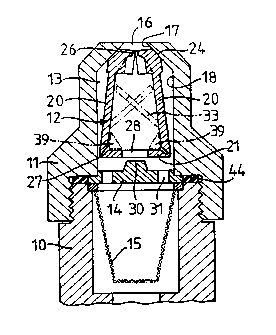
Referring to FIGURES 1 to 3, the spray nozzle
primarily comprises a hollow inlet body 10 on which a
hollow member in the form of a cap 11 is releasably
mounted, and a movable device 12 movable within a cylinder
13 defined primarily by the cap. The spray nozzle may
optionally also be provided with static member 14 and/or a
filter 15.
The cap 11 provides an outlet opening 16, and has a
comically inclined internal ramp surface 17 leading from
the opening 16 to an internal cylindrical surface 18 around
the cylinder 13.
The movable device 12 is in the form of a flexible
body moulded from plastics material so as to comprise parts
which form arms 20 connected together by a head 21. Each
arm 20 provides, on its free end portion, a nozzle surface
22, at least one abutment surface 23 (FIGURE 3) and a
slider surface 24 (FIGURE 2) in a predetermined mutual
configuration. In the embodiment shown in FIGURES 1 to 3,
two arms 20 are provided and the surfaces 22 are configured
so that when the surfaces 23 abut ( FIGURE 1 ) the surfaces
22 define between them a discharge orifice 26 smaller than
and concentric with the outlet opening 16.
The head 21 is dimensioned to be a sliding fit in the
cylinder, and is provided with an axial port 28 providing a
restricted flow path for fluid to flow into the movable
WO 94/13409 PCT/GB93/02475
11
device 12. 2 1 2 8 0 0 8
Each arm 20 is joined to the head 21 by an integral
resilient hinge 27 so that the arms can be swung together
against an inherent resilient resistance from the "as
moulded" condition shown in FIGURE 3 for insertion of the
device into the cylinder 13 so that the slider surfaces 24
are in contact with the ramp surface 17 (FIGURE 2) in the
normal position of the device 12.
The ramp surface 17 is inclined to the central axis
of the cylinder 13 at an angle determined so that the
reaction to forcible engagement of the slider surfaces with
the ramp surface (because of the radially outwardly
directed force applied to the arms by said resilient
resistance) produces a rearwardly directed bias acting to
urge the movable device axially away from the outlet
opening 16 and towards the normal position, e.g. about 30°.
In the normal position said abutment surfaces 23 are
separated so that the surfaces 22 no longer define any
discharge orifice 26 and merely lie in a relatively wide
flow path 29 to the rear of the outlet opening (FIGURE 2).
In use, in the absence of the static member 14 and
filter 15, when fluid is initially supplied to the nozzle,
the initial resistance to flow through the nozzle is
primarily determined by the area of the restricted flow
path i.e. the area of the port 28, the liquid will
initially flow through the wide flow path 29 between the
arms to the opening 16 until the force imparted to the head
21 (which serves as a piston under these conditions) is
sufficient to overcome the bias (and friction of the
engagement of the surfaces 24 and 17) and thereby drives
the device to move forwards towards the outlet. This
forwards movement causes the free end portions of the arms
to be forced towards the axis, as the surfaces 24 traverse
the ramp surface 17, until the abutment surfaces 23 abut
and the discharge orifice 26 is formed when the device
WO 94/13409 ~ PCT/GB93/02475
12
reaches the operative position. In the operative position
the ramp surface 17 serves also as a sealing abutment
surface and the slider surfaces 24 serve also as sealing
surfaces which engage the surface 17 to provide a seal
preventing fluid from by-passing the orifice 26; and the
resistance to flow through the nozzle is greater than the
initial resistance and is determined primarily by the
dimensions of the orifice 26.
The wide flow path 29 preferably has a minimum flow
cross-sectional area about the same as that of the outlet
opening 16.
The initial flow serves as a flushing flow to remove
particles of matter which could otherwise restrict or block
the orifice 26.
The simple example dust described involves a
compromise between the necessity of generating a sufficient
piston force and the desirability of keeping the port 28
sufficiently large to reduce the probability of the port 28
becoming blocked. This compromise is not significant where
the fluid supply is sufficient, but could be detrimental if
the rate of said supply is restricted. In the latter case
the compromise can be avoided by locating a static flow
restrictor 30 in the cylinder so that it restricts the port
28 in the normal position of the device and until the
device has moved forwards to take the port clear of the
restrictor, and has thereby moved the arms radially towards
each other to an extent sufficient to cause the resistance
to flow to be substantially determined by the spacing
between the surfaces 22 and/or 23. The static restrictor
30 is arranged to permit a flushing flow, and also serves
as a plunger or wiper to clear the port as the device
returns to the normal position.
The restrictor may be dimensioned to close the port
completely in the normal position, and, if the head 21 of
c
s
WO 94/13409 T B93/02475
13 21 280 ~
the device is a sufficiently close fit in the cylinder, the
restrictor and head will serve as a non-return valve, to
prevent further, i.e. leakage, flow through the nozzle,
and, if the filter 15 is included, to keep the filter
bathed in the fluid.
However, the head is preferably a clearance or free
sliding fit in the cylinder, and, if a non-return valve
function is required, the static member 14 is employed.
The static member is primarily an apertured disc in which
the apertures 31 do not register with the port 28 so that
when the head abuts the disc the port is closed whilst part
of the surface of the head remains exposed for application
of fluid pressure via the apertures 31, as shown in FIGURE
2.
In such a form of the spray nozzle, the disc 14 is
positioned to limit the stroke of the device so that in the
normal position the surfaces 24 remain in contact with the
ramp surface 17 whereby to maintain said rearwards bias and
force the piston to abut the disc. Initial forwards
movement is thus initiated by the pressure of the fluid
supply imparting the required minimum force to the piston,
prior to commencement of flow through the flow passages.
The restrictor 30 may optionally be provided or
mounted on the disc 14, as shown.
The movable device may be moulded to provide vanes 33
to impart rotation to the flow, e.g. as shown in FIGURES 1
and 5; or an extra arm or arms 34 carrying a vane 35 may
be provided on the device e.g. as shown in FIGURE 5. A
swirl vane 37 may be provided on the restrictor 30, and the
ports 31 may be inclined to promote swirl as indicated in
FIGURE 4. The arms may have lateral extensions 45,
indicated in broken lines in FIGURE 5, which abut in the
operative position to provide within the arms a smooth
walled, almost circular in section, swirl chamber 46
21 280 08
14
(FIGURE 6).
The shape and number of the discharge orifice or
orifices is determined by the form of spray required. For
example, the abutment surface 23 on an arm 20 may lie
between two nozzle surfaces 22 each of which extends to an
edge of the arm, as shown in FIGURE 7, so that in the
operative position the edges abut the surface of the outlet
opening 16 with the result that a pair of discharge
orifices 26 partially concomitant with the opening 16 are
formed within the opening by the surfaces 22.
More than two arms 20 may be employed, e.g. three arms
as shown in FIGURE 8, at equal or unequal angular
15 intervals around the head.
Where the discharge opening 26 is non-circular, e.g.
elongate, as shown in FIGURE 9, or where a spray pattern
asymmetric to the axis or of non-circular form is required,
20 the axial orientation of the device 12 in the cylinder 13
may be determined by any suitable guide means. For
example, the port 28 may be of keyhole form, and a modified
form of the static member 14 having a guide finger 38
thereof parallel to the axis to engage in the eccentric
portion of the port, as shown in FIGURE 12, may be employed
as the guide means. However, it is preferred to provide
the cylinder with an axially directed rib 50 to engage in
a recess 51 in the head (FIGURES 2 and 3) or to provide a
keyway in the cylinder to receive a radially directed
projection on the periphery of the head 21. As can be seen
in FIGURE 6, the hinges 27 provide chordal flats 53 on the
periphery of the head, and to prevent rotation of the
insert, the cylinder may have corresponding chordal flats,
not shown. Markings 54 (FIGURE 7) may be provided on the
cap 11 to indicate the orientation of the device 12 and
thus the spray pattern.
The resilient resistance from which the bias is
,;
WO 94/13409 ~ ~ ~ ~ 15 PCT/GB93/02475
derived may be supplemented, e.g. by extending the vanes 33
to abut so as to urge the arms 20 apart; by using the vane
35 on the arm 34 to urge the arms 20 apart; by forming
buttresses 39 on the arms 20 to engage and react against
the head to urge the arms radially outwards (FIGURES 1 and
3); or by any combination thereof.
A stop surface or flange 42 on the cap may usefully
be employed to seal against the end portions of the arms to
prevent flow bypassing the discharge orifice or orifices;
and in such embodiments the slider surfaces 24 may be
provided by narrow ribs 43 on the arms 20 to reduce
friction in the engagement with the ramp surface (FIGURES
10 and 11).
The end portions of the arms 20 may, in the operative
position, project forwards beyond the outlet opening 16
(FIGURE 10), to be co-terminus with the outlet opening
(FIGURE 8), extend into the outlet opening (FIGURE 7) or
terminate to the rear of the outlet opening (FIGURE 1).
In all embodiments, movement (and optional flexing)
of the movable device serves to dislodge, and/or beak up
solid or non-fluid deposits, on the device, for removal
thereof together with other particles by flushing flow, for
automatic self cleaning or unblocking of the nozzle.
Repeated interruption of the fluid supply can be employed
to facilitate cleaning and/or unblocking of the nozzles.
The invention is not confined to details of the
foregoing examples, and many variations and modifications
are possible within the scope of the invention.
For example, the cap may provide merely the stop
surface or flange 42 or the ramp surface 17, the remaining
cylinder surfaces 17 and 18 or surface 18 being provided by
the inlet body 10 or by a suitably shaped insert (not
,shown) inserted into the interior of the nozzle.
21 280 0 8
16
In the event of a shaped insert being employed,
components such as the static member 14 and/or filter 15,
together with the device 10, or any thereof, may be
preassembled with the insert to form an assembly to
facilitate adaptation of a known form of nozzle, or repair
or refurbishment of a nozzle in accordance with the
invention.
The member 14 and filter 15 need not be located at a
junction between the cap and body, even though it is
convenient to locate the member 14 by means of a junction
seal washer 44 and a locating flange on the filter as shown
in FIGURE 1.
The terms and expressions employed herein are by way
of example and include within the scope thereof applicable
generic terms and synonymous and functional equivalents.
For example the invention further provides and
includes a spray nozzle having a hollow member defining an
outlet opening and a device movable within the nozzle
between a normal position in which the outlet opening is
unrestricted or minimally restricted and an operating
position defining a discharge orifice within or proximal to
the outlet opening and having a flow cross-sectior3al area
less than half that of the outlet opening.