Note: Descriptions are shown in the official language in which they were submitted.
' O 94/14256 PCT/IJS93/11188
2128101
DEVICE AND METHOD FOR ADAPTIV~LY ADJUSTING
LOADING GAPACITY FOR A NODE IN A PACKETIZE~)
COMMUNICATION SYSTEM
Field of the Invention'
"
The present invention relates generally to capacity in a
communication system. More particularly, the present
10 invention relates to ~a device and method for adjusting loading
capacity in a packet-based communication system.
Background
1~ Communication resources such as radio frequency
channels have a limited capacity. Nevertheless,
communication needs have continued~to increase. More 'users
are continuaily~ being added to communication systems. The
' efficiency and ~reliability of a communication system is
20 ~ closely related~to~its;system:capacity. System capacity is
generally~based~on~the~ number~of available channels and the
throughput rate~associated~therewith. ;Without technical
mprovements~th~at ~ provide for ~loading capacity adjustment,
u sérs~;may~face impaired ~service, or ;ultimately, a complete
25 ~ ~lack~ of available~service~
Trunked~ mmun~ication~systems~su~h~stelephoneand
cellular systems~ typica!ly~include~an inherent ~i~ed upper
threshold for system càpacity. in a~ digital communication
30~ system, this upper; threshold i s~ an~upper ~iimit that is based on
the number o~ available~ c~annels and the~ throughput rate.
When~the~upper li`mit~of the~system's capacity is reached, the
sy~tem is unable~ to~ carry~ data traffic (i.e., call blocking
occurs). For a fixed ~bandwidth digital communication system,
35 ~typically maximum ;throughput is ~limited to a predetermined
: ~ :
~ .
WO 94/142S6 rCT/US93/11188
2~2~lol 2
upper limit that is allowed for a channel. In addition, for a
voice channel, if more throughput is allocated to digital
representation of voice on the channel, fewer channels can be
simultaneously utilized. As traffic on the system increases to
5 a level that approaches the fixed;~ùpper limit of the systems
capacity, if no flexibility is provided for adjusting the
traffic-carrying eapacity of the system, call biocking is highly
likely to occur.
Thus, there is a need for an adaptive capacity loading
device and method for providing a more efficient
communication system by lowering the probability of call
blocking as eall traffic approaehes the upper limit of the
system s capacity.
1 5
~ Summary of the Invention
An adaptive loading capacity device for a node and a
2 0 method~for adaptively~ adjusting a;loading eapaeity for a node
are set~forth. The~device~automatically~adjusts~a data rate of a
vocoder for the;-node in a;~ pa~ket-based linked communication
system. ~ The~device includes~a~data traffic-determining unit,
operably~coupled~;to receive~data traffic, for determining
25~ ~whether~a~eurrent~data~rate~(CDR)~ofthedatatrafficwithin
the~node;~exeeeds~a~predeterminedthrésholdand,wherethe
;C:DR~exeeeds~the~ predetermined ~threshold, for determining an
adjusted- -throughput~ data~rate; (ATDR)~ for comrnunication
linkslstation~s) utilizing ;the system in accordance with a
; 30~ predetermined~ strategy~ ~such that further links/station~s) may
utilize the~systern.`~ The data traffic includes frames that
nclude packetized~information for coded speech data traffic.
Frames~aiso inc~ude â~;requested;~data rate ~RDR) and a ¢urrent
data rate (CDR)~ for the coded speech data traffic. The device
3 5 further includes an ~ automatic adjusting unit operably coupled
~ 94/14256 21 2 81 01 PCT/US93/11188
to the data traffic-determining unit for, upon comparing the
RDI~ with the ATDR and determining that the R[)R is greater
than the ATDR, automatically adjusting the RDR downward to
equal the ATDR. In this manner system capacity is increased,
5 and a probability of call-blocking is reduced in the system.
The method implements the functions of the device as
described above.
Brief Descriptions of the Drawings
FIG. 1 is a block diagram of a first embodiment of an
adaptive loading capacity~devicé in accordance with the
present invention.
1 5
FIG. 2 il~ustrates~ a frame format for basic information
contained~within a~frame~in the system in accordance with the
present invention.
2~0~ F!G. 3 is~a^~block~diagram of an adaptive loading capacity
device for a ~node~ together ~with~a~ plurality of stations in a
packet-based communication ~system in accordance with the
present invention.~
25 ~ FIG. 4 iS a~block diagram~ showing a~station of FIG. 3 with
g~reàter~ ~ particular~ty. ~
FIG. 5 is~a ~block ~diagram of ~a~.communication system
utilizing an adaptive~capacity loading device in accordance
30~ Iwith~the~present invention. ~
FlG. 6 is ~a~flow~;chart setting ~forth a first embodiment of
steps~in accordance~with~the method of the present invention.
W{) 94/14256 PCT/US93/11188 -- I
2128101
Fl(3. 7 is a flow ehart illustrating the step of
automatieally adjusting the RDR downward to equal the ATDR
of FIG. 6 is shown with more particularity.
., .
FIG. 8 is a flow ehart setting f~orth a seeond embodiment
of steps of the method of the present invention.
FIG. 9 is a bloek diagram of a mieroproeessor
oonstrueted and arranged (programmed) to provide the adaptive
loading eapaeity deviee of the present invention.
Detailed D-scrlption oS a Preferred Embodimer~t
The present; invention~ provides an deviee and method that
readily identifies~ a eoded speeeh data rate loading problem at
a node in a eommunieation system where the loading may l~ad
to eall bloeking~due to fi'lling of the system eapaeity. Then, the
present invention: automatieally red~ees the eoded speeeh data
20 ~ ~ate,~thereby~redueing the data~rates~available for additional
ealls~ that may~be~added to the~ system.~ This aetion allows
subsequent~ealls to'be~placed~without eall bloeking7 allowing
more ~ealls at~a~redueed~ ;voiee quality during, periods of heavy
t r~af f i e . ~
FlG. ~ 1, numeral~;~100, is a~ bloek diagram of a first
embodiment ~of~;an~adaptive~ loadi~g eapaoity deviee in
;aeeordanee~with~ the~present invention.~ The adaptive loading
eapaeity d~viee~(102)~ ~automatieally adjusts a data rate of a
30 ~ voeoder~for;a node~in~a;~paeket-based linked eommunieation
system. The ~eviee ineludes a data traffic-determining unit
(104) and an automatic adjusting~ unit ~(106).
The~ data~tràffic-determining unit (104) of the node is
i ~ 3~ operably ooupled ~to receive data traffic of the oommunication
~ 94/14256 PCT/US~3/11188
~ 2128101
system, generally from multiple nodes and, where selected, at
least one of a plurality of stations. A station is an
inpuVoutput point of the communication system, i.e.,
generally a single addressable site on a LAN that is typically
5 implemented as a computer and selected peripherals. The data
traffic-determining unit (104) determines a current data rate
(CDR) of data traffic within the node and determines whether
the CDR exceeds a predetermined threshold. The
predetermined threshold is an upper rate limit for the system.
10 Where the CDR exceeds the predetermined threshold, the data
traffic-determining unit (104) determines an adjusted
throughput data rate (ATDR) ~for communication
links/station(s) utilizing the system in accordance with a
predetermined strategy.~ The strategy is to provide an
15 adjusted rate that is lower than the current rate, thereby
; allowing the node~ to ~throughput data traffic for a greater
` number o~ calls. The ATDR typically represents an upper rate
limit or capacity of the system ~or, alternatively~ an upper rate
limit decremented by~ a~ buffer~ ~value. The buffer value prevents
20 a~ slight increase~in data~; rate from filling the capacity of the
system,~ causing; ~call-bl~ocking.
Data~traffic is~ packetized into frames that include a
r equested data;irate~(RDR). ~ The~strategy implemented includes
25 ~comparing the;magnitudes of the~RDR and the ATDR and
reducing the ~RDR~ to the~ATDR.~ ~ ~Thus, where a RDR of a frame is
greater~-than~the~ATDR,~ t he~device~automaticallyadjuststhe
R~DR ~downward~to~substantially~ equal the~ATDR. The adjusted
RDR i~ incorporated into frames that are transmitted to
,
30 ~ coupled~nodes~and~stations, which then automatically adjust
the~GDR to substantially~equal the ~request~ed RDR. The
reduction of the;~ CDR~;allows further !inks/station(s) to utilize
the ~ system.
~ 3 5
,~:
,
WO 94/142S6 PCT/IJS~3/11188 ,,
2 ~ ~ G
As illustrated in FIG. 2, numeral 200, the data traffic
comprises frames that include packetized in~ormation ~or
coded speech data traffic (208). The frames further înclude a
requested data rate 5RDR) (204~ and a current data rate (CDR)
5 (206) for the coded speech data traffic. In addition, each frame
typically includes a frame descriptor (202). The coded speech
data traffic comprises packet~ of digitized code that
represent speech information from calls made by
comrnunication system users.
1 0
The automatic adjusting unit (106) is operably coupled
to the data traffic-determining unit ~104). The automatic
adjusting unit (106) compares the RDR of each frame with the
ATDR r~ceived from the data traffic-determining unit (104
1 5 and determines whether the~ RDR is greater than the ATDR.
Where the RDR is greater than the ATDR, the automatic
adjusting unit (106) automatically adjusts the RD~ down~ard
to equal the ATDR. Where the RDF~ is less than or equal to the
ATDR, the automatic adjusting unit (106) typically maintains
~0 the current Rl)R. ~ Where the RDR is adjusted to a lower rate
(i.e., the ATDR is less than the RDR), the probability o~ call-
blocking is reduced~since a portion of ~he capacity of the
i ~ ~ system becomes available for additional calls. The adjusted
;~ ROR is incorporated~ into frames that are transmitted to
25 coupled ~nodes and~stations, which ~then automatically adjust
the GDR to substantially~equal the requested RDR. Clearly,
there is some loss :of; voice quality in tlle received
transmissions, ~but~the loss is~ typically acc~ptable and call-
blocking is reduced. ;
3 0
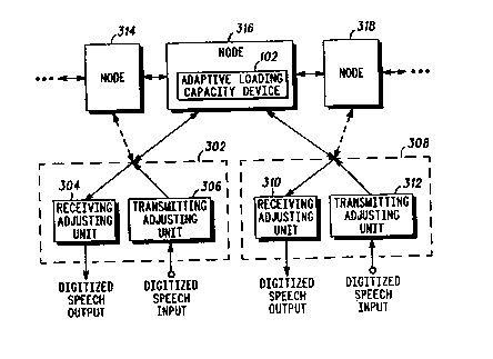
FIG. 3, numeral~ 300, is a block diagram of an adaptive
loading capacity ~device~ o~ a node where a plurality of nodes
function together -with~ a~ plurality of stations in a packet-
based communication system in accordance with the present
35 invention. FlG. 4, numeral 400, is a block diagram showing a
: ~ :
"V 94/14256 21 2 81 01 PCT/IJS93/11188
station of FIG. 3 with greater particularity. The adaptive
loading capacity device (102), as described more fully above,
is coupled to transmit and receive packetized coded speech
data traffic from a plurality of nodes (314, 316, 318, ...) and
stations (302, 308, .. ). Each station includes a receiving-
adjusting unit (304, 310, ...), operably coupled to a at least a
first node for, upon receiving ~ frame of packets of coded
speech data traffic from the node (102, ...), sending a received
RDR of the frame to an encoding-initializing unit (406~ of the
10 station and decoding the packets at a rate defined by the CDR
of the frame. Each station also includes a transmitting-
adjusting unit (306, 312, ...) that is operably coupled to the
node (102, ...)~ for receiving digitized speech data, encoding
said data into packets and transmitting the encoded speech
15 packets at the RDR that has been adjusted to be substantially
equivalent to the recèived RDR. It should be noted, for
example, that in~ an implementation in which each of the nodes
is iocated in a separate orbiting satellite of a plurality of
.
satel!ites, typically ~ a station receives frames of packets
20 from, and~transmits;frames of packets to, a satellite that is
predetermine~ with~respect~to its o~rbital position. That is,
generatly a ~station ~will~ receive/transmit at least fromlto the
orbiting ~ satellite~ ~that~ is in greatest proximity to the station.
Also,~it is~clear that,~with~ resp~ct to system capacity, where
25 ~ ~ the~station ~deteots~a highly loaded n ode, as predetermined, the
station ~may-~further~make ~an adjustment to receive/transmit
frorn/to another ~ node.~
The transmitting-adjusting unit (306, 312, ...) typically
3~0 ~ includes ~an~ encoding-initi~alizing unit (402), a data rate
setting unit (404)~, and a transmitting unit (406). The
` ~ ~ encodi~ng-initializlng~ unit ~(402),; operably coupled to receive
digitized~ speech~;input and to the receiving-adjusting unit
304), encodes and packetizes the digitized speech packets
,:
- : :
~: :
WO 94/14256 . PCT/USg3/11188 .
LO~ 8
utilizing the CDR and initializes an RDR of frames to be
equivalent to the received RDR.
The data rate setting uni,t~ ~404) is operably coupled to
5 the encoding-initializing unit '(402) and is utilized for setting
the CDR of the frame to the requested RDR for the station and
inserting the CDR and RDR into the frames.
The transmitting~ unit (406) is operably coupled to the
10 data rate setting unit (404), for transmitting the frames to a
preselected node.
FIG.' 5, numeral 500, is a block diagram of a
communication system utilizing a first embodiment of an
15 adaptive capacity loading device in accordance with the
present invention. ~ ~ln the~first embodiment a plurality of
nodes (node 1, node 2, node 3, ..~) are operably coupled, as
;preselected, and a~pluralityi of ~stations ~Station 1, 516;
Station 2, 518;~Station~3,~ 520; Station 4, 522, .~.) are operably
20~ ~coupled to at least one of the~ nodes such that each station has
a communication~path~ with; other~stations in the system. In
the embodiment,~ each'of the ~nodes~(504, 506, 508, ..~) includes
an~adaptive capacity~loading`~device'(ACDL) (510, 512, 514, . )
n ~ thatoperates~as~described~above.~ Glearly,inanalternate
25~ embodiment, a'system`~may~be arranged so that only nodes that
are~more Iikely~;to~ experience high~ traffic rates include the
device of the~ present' invention.~By ~determining an adjusted
throughput data~rate ~ATDR)~for communication
I inkslstation(s) ~utilizing the ~system in accordance with the
3~0 ~ -precletermined~ strategy~descrlbed~;~abovej further
:links/stàtion(s):: ~may~;~ utilize~; the ~system.
It is to be ~understood that the couplings of the
- communication~ ~system may~ accommodate frames/packets of
35~ data traveling in~ both~`directions. The frames may carry data
: : :
: :~:: : : ~ :: :
tO 94/142~6 2 ~ 2 81 01 PCT/US93/11188
packets and acknowledgement packets for many different calls
or virtual circuits. Thus, each line may be considered as
constituting many different paths for accommodating many
different calls from many different stations.
FIG. 6, numeral 600, i~ a flow chart setting forth a first
ernbodiment of the steps in accordance with the method of the
present invention. The method of the invention provides for
automatically adjusting a data rate of data traffic of a
10 vocoder for a node in a packet-based linked communication
system, where the data traffic comprises packets that include
at least information ~or coded speech data traffic and frames
that include a requested data rate (RDR) and a current data
rate (CDR) for the coded speech data traffic.
~
The method shown in Fl(3. 6 includes the step of first
determining whether a current data rate (CDR) of the data
traffic within the node exceeds a predetermined threshold
(602) and, where~the CDR exceeds the predetermined threshold,
20 determining an acljusted~throughput data rate (ATDR) (604) for
links/station~s) utiiizing~ the system in accordance with a
predetermined~ ;strategy ~ such that the system may
accommodate traffic; for further calis. The predetermined
strategy includes~provision of ~an adjusted rate to a node
25 where the~ adjusted~'rate is lower than the current rate,
thereby~allowing~the~ node to throughput data traffic for a
greater~ number of ealis.~; ~An ;RDR o f each received frame is
compared with the ~ATDR. Where the received RDR is greater
than the ATDR, the RDR i~ automaticaily adjusted downward to
30 be substantially~ equal to~ the ATDR. Thus, for example, as
iliustrated in Fi(~.~ 7, ~numeral 700, the~ step of automatically
a~justing ~the RDR downward to equal~ the ATDR ~FIG. 6)
includes reducing the~ RDR to an A~DR that is equivalent to one
of: a predeterrnined upper limit of the system'~ capacity (702)
35 and the predetermined upper limit of the system's capacity
: .
WO 94/1425G PCTIUS93/11188
2~ ~ ~ o
minus a predetermined buffer value (704). The adjusted RDR
is incorporated into frames that are transmitted to coupled
nodes and stations, which then automatically adjust the CDR
of received frames to sllbstantially eqllal the requested RDR. In
this manner, a probability of call-blocking is reduced in the
system.
FIG. 8, numeral 800, is a flow chart setting forth a
second embodiment of the steps of the method of the present
invention. In the second embodiment, the method furt~er
includes implementation of the following steps by the
stations: (1) upon receiving a~ frame of coded speech data
traffic from a node,~ sénding a rèceived RDR of the frame to an
encoding-initializing unit of the transmitting-adjusting unit
` 1 5 of the station and aiso decoding~packets of the frame at the
CDR l802), and (2) transmitting an encoded speech frame (804)
by~ (A) encoding and packetizing the digitized speech data
utilizing the CRC and initializing the~ RDR of the frame to be
sub'stantially equivaient to the received RDR (806); (B) setting
`20 t he CDR~to the received RDR and inserting the CDR and the
received ~RDR; into~ the frame~;(808)~;~; and (C) transmitting the
h ~ framei to a preselected ~node (81Q). ~
Though hardware ~embodiments have been discussed, each
2~5~ ~ of the ~elements~ ;of ~the~ hardware can be alternatively
implemented;~by incorporation ~of the;~steps of the method, FlGs.
6-8,~which~;~clearly~implement~the~functions of the hardware,
in ai ~'computer program. ~
30~ FIG. 9, numeràl 900,' is~'a block diagram of a
;;micr~processor ~constructed ~and arranged ~programmed) to
provide the adaptive~loading capacity ~device of the present
inventio~. The microprocessor (902) is programmed to provide
at least the functions ~ of the data~ traffic-determining unit
(104) and the automatic adjusting unit (106), as described
'~ 94/14256 PCT/USg3/11188
21~8101
above. The device further includes, associated memory
circuitry (904), and associated circuitry for coupling the
microprocessor to the node(s) (906) and to receive data traffic
from the stations/nodes (908,...).
Although exemplary embodiments are described above, it
will be obvious to those skilled in the art that many
alterations and modifications may be made without departing
from the invention. Accordingly, it is intended that all such
10 alterations and modifications be included within the spirit and
scope of the invention as defined in the appended claims.
"
We claim:
~:
;:: :