Note: Descriptions are shown in the official language in which they were submitted.
A~3}3 HENSC~EL 5902 Netph0n 2, 01.12.1992
Waggon Union Gmb~
Block brake f or rail vehicle~
The invention relates to a block brake for rail
vehicles in which a brake linkage is acted on by a brake
cylinder via brake blocks which consist of brake block
5 shoes and brake blcck shoe insert~ acts radially on at
least one wheel 3et of the bogie of the rail vehicle.
In practice, brake blo~ks for rail vehicles are
known, in particular in the field of goods traffic, via
which the entire braking of the rail vehicle take~ place
up to a maximum permisible speed of 120 km/h. In the~e
known block brakes, the brake block~ which concist of
brake block ~hoes and brake block shoe inserts act
directly on the running tread of the tyre of the wheel of
the wheel set. The brake blo~ks are attached on a brake
beam which is usually configured in the shape of a
tri~lgle (brake triangle). ~he brake block shoes with the
brake beam are mounted in an articulated fashion in the
rail vehicle or in the bogie of the rail vehicle on its
frame and are acted on by a brake cylinder Yia a ~rake
pull rod with the intermediate connection of the centre
brake linkage and possible connecting levers between the
brake beams.
:- This block brake which is described above fulfils
its function ~atisfactorily up to the aforesaid speed
with loads of up to 22.5 t per axle, customary in goods
traffic, and consists of si~ple components which are
economic to manufacture and can be serviGed with a low
degree of expenditure. ~owever, it has proven a disadvan-
tage that the braking heat which is produced during
braking leads to damage to the tyre of the wheel and to
the running tread.
The con~equence of this is a rough and bumpy
running tread and possibly even the formation of frac-
tures in the running tread. As a result of the mechanical
effect of the brake blocks on the running tread corruga-
tion~ are additionally f ormed on the running tread. As a
result of these change~ to the running tread of the tyre
r,r . ~ : . ~,
'`'.~ . ~ ' ~' '
7 .. :~
'~r,~ : , "
Ij", ,. . . : , , ~ '
-- 2 --
of the wheel a very loud wheel noise is produced. When
the tyre of the wheel is damaged as a result of the
formation of fractures, the wheel set must be replaced.
It is also disadvantageous that, in order to
limit the braking heat produced during braking the
penmissible braking capacities are far below the range
which would be theoretically achievable.
The object of the present invention consisted in
arranging the block brake, which is per ~e economlcal, in
a rail vehicle and constructing it in such a way that
high~r braking capacities can be achieved, that damage to
the tyres of the wheels of the wheel set is avoided and
that the wheel noise of the wheel sets is minim;zed.
According to the invention, this object is
achieved in that at least one rotationally symmetriGal
brake body is permanently arranged on the wheel set shaft
of the wheel set between the wheel discs of the wheel
set, on the outer face of which brake body the brake
block which is acted on rests. By virtue of this measure
according to the invention, the sLmple and economical
components of the known blo~k brake are basically pre-
served and at the same tLme a possible means is provided
of realizing higher braking capacities, of keeping the
running tread of the tyre of the wheel free from braking
heat and of avoiding the formation of corrugations on the
running tread.
According to the invention, in each case at least
one brake block can be provided on each side of the wheel
~et shaft and both brake blocks, acting radially on the
wheel set shaft, rest on the outer face of the brake body
when activated.
By means of this design of the invention, the
wheel axle is kept free from supplementary longitudinal
forces so that even during the braking process the wheel
set can adjust itself to the greatest possible degree to
the course of the track.
Ac~ording to an exemplary em~odiment of the
invention, two or more brake bodies are arranged on the
wheel set shaft and for each brake body in each case one
. ~
-
, - :
b
~rake block which acts on the said body i5 arranged on
each side of the wheel set shaft. ~y increasing the
number of brake bodies on a wheel set shaft a higher
braking capa~ity can be achieved.
According to the invention, the brake block shoes
are attached on brake block hangers and mounted on a
brake beam. Furthermore, according to the invention, when
two brake bodies are arranged on the wheel set shaft the
brake beam is constructed as a brake triangle. ~y means
of this arrangement according to the invention and design
of the brake components, the greatest possible degree of
approximation to the customary block brakes is achieved
and thus a sLmple and economical design of the block
brake according to the in~ention is ensured.
1~ According to an exemplary embodLment of the
invention, each brake block ~an be guided axially on the
brake body~ According to a further exemplary embodLment
of the in~ention, the brake beam is guided laterally on
the frame of the bogie or the subframe of the rail
2 a vehicle. By virtue of these measures, the lateral
guidance of the brake blocks and thus the operating
reliability are ensured.
Details of the invention are explained with
reference to an exemplary eDbodiment in the drawing, in
which:
Fig. 1 shows the vertical longitudinal section through
part of a bogie of a rail vehicle with the block
brake according to the invention,
Fig. 2 show~ a plan view of the part of the bogie
according to Fig. 1,
Fig. 3 shows a front view of the part of the bogie
according to Fig. 1.
In the exemplary embodiment of the invention
illustrated in the drawing, the invention is illustrated
on the bogie of a double-axle railway goods wagon. The
wheel set (1) which consists essentially of the wheel set
shaft (2) with the wheel discs (3) is in this case, as is
known in practice, attached by means of external axle
bearings (4) and leaf suspension springs (not
.. ;, . ~ - - .
. . . -: .
:. . :. .,
.:
.: , ~ :. : . ~ ,
.. : - - . .
. -
; :. . : ~ . .
r ~ 3
-- 4 --
illustrated) with the intermediate connection of link
suspensions (also not illustrated) on suspension (5) of
the subframe ~6) of the railway goods wagon. Between the
wheel di~es (3) of the wheel set (1), in each case one
rotationally symmetrical brake body (7) is arranged fixed
in terms of rotation on the wheel set ~haft (2) on each
side of the centre longitudi~al axis of the railway goods
wagon. The rotationally symmetrical brake body (7) has
here a cylindrical outer face ~8) and a wheel flange (9)
which protrudes beyond the outer face (8).
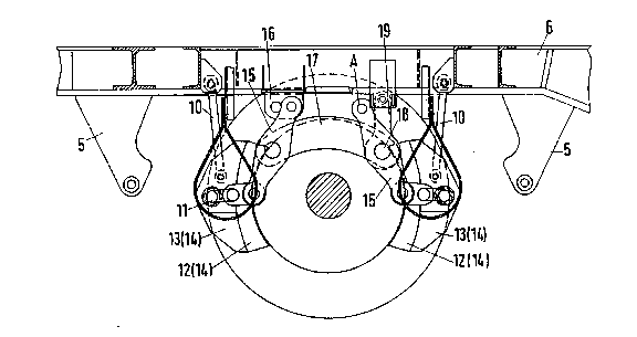
In the subframe (6) of the railway goods wagon,
in each case one brake beam (11) is attached in an
articulated fashion vi~ ~rake block hangers (10) on each
side of the wheel set (1). The brake beam (11) bears at
its two longitudinal ends in each case one brake block
(14) consisting of brake block shoe insert ~12) and brake
block shoe (13). The brake block shoe inserts (12) of
each brake block shoe (13) are located i~ front of the
outer face (8) of the brake body (7~.
In the centre, each brake beam (11) is attached
in an articulated fashion to a brake lever (15), one
brake lever (15) being mounted with its upwardly protrud-
ing end in an articulated fashion to a fixed point
bearing (16) of the subframe (6) of the railway goods
wagon. The second brake lever (15) bears at its upper
free end (designated by A) a brake pull rod (not illus-
trated). In the centre, both brake levers (15) are
connected to one another in an articulated fashion by
means of a brake lever connector (17). The brake lever
~0 (l~) which bears the brake pull rod is also connected in
an articulated fashion to a brake hanger (19) via its
joint (18) which bears the brake lever connector (17),
which brake hanger (l9) is also attached to the subframe
(6) of the railway goods wagon in an articulated fashion.
Via the brake pull rod (not illustrated) and a
centre brake linkage which is also not illustrated but is
k~own from practice, the wheel set (1) is braked by means
of a brake cylinder by the brake blocks (14) being
pre~ed against the outer face (8) of the brake body (7
,., . ~ ~
: : . .
,` . "~
s -
by means of the brake block shoe inserts (12).
According to the invention it is also conceivable
to arrange a wheel flange on each longitudinal side of
the brake body (7) instead of one wheel flange (9) of the
brake body (7) or to provide the outer face (8) of the
brake body (7) with a contour, for example a convex or
concave contour, whi~h guides the brake block (14)
laterally. It is also conceivable, for the purpose of
guiding the brake beam (11) laterally, to guide the said
beam (11~ in the subframe of the railway goods wagon by
means of lateral guides.
Basically, with the block brake accoxding to the
invention the guidance of the brake blocks (14~ on the
brake body (7) can take place firstly in such a way that
the required transverse movements of the wheel set (1)
take place in relation to the brake beam (11) and thus in
relation to the brake block (14) and secondly in such a
way that the transverse movements of the wheel set (1~
are transmitted to the brake beam (11) and thus to the
brake blo~k~ (14), and that the axle braking linkage
which consists of br~ke blocks and brake beam also
oscillates during these transverse movements.
s" . ~
"~
. . .