Note: Descriptions are shown in the official language in which they were submitted.
212~126
. .
PROSTEIESES FOR E~JEE REPLACEMENT
This invention relates to prostheses for knee
replacement, particularly those for total knee replacement
operations.
Most of the knee replacement prostheses in common use
are of the condylar replacement type where the arthritic
joint surfaces are resected and replaced with cooperating
metal and plastic surfaces. In designing a satisfactory
prosthesis, the aim is to replicate as far as possible the
natùral movements of the knee. However, the knee is a
complex joint and the transverse axis of pivoting moves
backwards and forwards as the knee pivots. There is
also a limited degree of axial rotation; such rotation
being biassed to the medial side of the knee. One of the
dif~iculties, however, in providing freedom of movement to
allow such motion is to ensure, at the same time, that the
artificial joint does not jam or dislocate in use.
The present invention provides a number of different
approaches to the solution to the above problem.
According to one aspect of the present invention, there is
provided a prosthesis for knee replacement which
comprises:-
(a) a femoral component having at least one condylarbearing surfaces;
(b) a tibial component having a tibial platform;
~8126
`;
(c) a meniscal component located between the
condylar bearing surfaces and the tibial platform; and
(d) guide means arranged to guide the meniscal
component for movement in an arc about a medially
displaced axis which extends substantially at right angles
to the tibial plate and preferably lies outside the area
of the tibial plate.
The prostheses of this invention are of the condylar
replacement type. In prostheses of this type, some or
all of the natural collateral and cruciate ligaments are
retained to give stability to the artificial joint.
Often, because of the difficulty in resecting the natural
joint surfaces without damaging the cruciate ligaments, it
is the practice to resect at least the posterior cruciate
ligament. However, the collateral ligaments are
generally retained.
Pre~erably, the guide means comprises a curved track
which is upstanding on the tibial platform and cooperates
with a recess in the meniscal component.
The tibial platform may include a stud extending
upwardly from the tibial platform, which engages in a slot
in the meniscal component. Preferably, such stud h~s~ ~-
head which is larger than the cross section of the st
and engages in a corresponding groove in the meniscal
component, thereby restraining lifting off of the meniscal
component from the tibial platform.
; ; 2~2~2~
According to a second embodiment of the present
invention, there is provided a prosthesis for knee
replacement which comprises:-
(a) a femoral component having at least one condylarbearing surface;
(b) a tibial component having a tibial platform and
an anterior-posterior centre line;
(c) a meniscal component located between the
condylar bearing surface and the tibial platform;
d) a stud upstanding from the platform and engaged
in a recess in the meniscal component in such a way as to
permit relative movement between the meniscal component
and said stud and yuide means, (normally remote from said
stud and said recess), for guiding movement of the
meniscal component relative to said platform in an arc
which is centred on an axis which is substantially at
right angles to the tibial platform, and is displaced
medially from the anterior-posterior centre line of the
platform.
As in the first embodiment of the invention, the stud
is preferably provided with an enlarged head which engages
in a groove in the meniscal component and restrains
lifting off of the meniscal component from the platform.
Preferably, stops are provided to prevent the
meniscal component sliding posteriorly or anteriorly
beyond a predetermined sliding limit so as to reduce the
2~12~
risk of dislocation in use.
In one embodiment, the stud slides in a slot in -the
meniscal component which is closed at one or both ends to
provide stops to prevent sliding movement of the meniscal
component in the anterior-posterior direction beyond a
predetermined limit. Where the slot is closed at both
ends, the slot and rail would be designed as 'snap-on'
engaging parts.
Guide means for guiding the meniscal component about
an arc centred on a axis medially of the centre line of
the tibial platform, are preferably formed by suitably
engaging surfaces on the tibial platform and meniscal
component. Preferably, such surfaces are curved and also
include an upstanding curved surface on the tibial
platform, engaging with the recess in the meniscal
component. Preferably, the guidance is such that the
axis about which the meniscal component rotates is centred
at the edge of the tibial platform or beyond its physical
extent.
Several embodiments of the present invention will now
be described with reference to the accompanying drawings,
in which:-
Figure 1 is a plan view of a first embodiment of atibial plate component in accordance with the invention,
Figure la is an elevational view in the anterior-
posterior direction of the tibial plate shown in Figure 1,
212~
Figure lb is a view taken in the direction of the
arrow X in Figure la,
Figure lc is a plan view of a meniscal component
designed for use with the tibial platform shown in Figures
1 to lb,
Figure ld is an elevational view of the meniscal
component shown in Figure lc, taken in the anterior-
posterior direction,
Figure le is a sectional view on the line A-A in
Figure lc,
Figure 2 is a plan view of a second embodiment of a
tibial platform and meniscal component shown in the
neutral or extended position o~ the knee,
Figure 2a shows the position with the plastic
meniscal component rotated 10 externally on the tibial
base plate,
Figure 2b shows the meniscal component rotated 5
internally on the tibial base plate,
F.igure 2c shows the method of engaging the meniscal
component on the tibial base plate,
Figure 3 is a plan view of a further embodiment
showing a tibial platform with a meniscal component in
place on the platform. The meniscal component is shown as
transparent, althouyh normally it would be opaque or
translucent,
Figures 3a and 3b show the meniscal component at
~12~12~
different degrees of rotation on the platform,
Figure 3c shows one method of installing the meniscal
component on the curved rail,
Figure 4a is a perspective view of a femoral
component,
Figure 4b is a perspective view of a meniscal
component showing the condylar bearing surfaces but
omitting the parts which engage with the tihial platform,
Figure 4c is an elevation showing the relationship
between the femoral, meniscal and tibial components, and
Figure 4d shows anterior and plan views of the
femoral and meniscal components.
Referring to Figures 1 to le, the tibial component
comprises a tibial platform 1, usually made from stainless
steel or other non-corrosive metal and having downwardly
extending projections 2 and 3 for engaging the platform in
non-rotatable manner in the resected end of a tibia. The
upper surface 4 of the platform has a flat horizontal
surface with an upstanding stud 5 located on the centre
line P-Q of the tibial component. The tibial platform is
cut away at 7 at the posterior side of the platform to
allow passage of the cruciate ligaments.
As can be seen best in Figure la, the stud has a
generally circular body and an enlarged head 8. Stud 5
extends upwardly from a raised portion 9 of the tibial
base plate. The raised portion 9 forms a central upper
2~12~
.
platform which is bounded by curved sides 10 and 11.
This central portion is typically about 2 to 3 mms higher
than the general plane of the surface 4 of the tibial
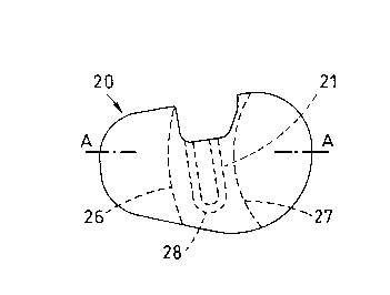
platform. A meniscal component 20 has a shape as seen in
plan view which is similar to that of -the tibial platform
1. However, it is slightly smaller in overall size than
the platform on which it is mounted. The meniscal
component 20 includes a slot 21 formed in the central area
of the meniscal component. Slot 21 includes an enlarged
groove 22, which is shaped to receive the stud and head 8
with some looseness between the stud and the recess to
allow some freedom of motion.
As can be seen more clearly in Figure ld, the
meniscal component is shaped with depressions 23 to
receive the condylar bearing surfaces of the femoral part
of the prosthesis. The meniscal component is thickened
in the central part 24, so as to provide additional
material Eor accommodating the slot and groove 21 and 22.
The underside of the meniscal component is also recessed
at 25 to provide a recess which extends from the anterior
to the posterior side and has smoothly curved surfaces 26
and 27O
Surfaces 26 and 27 cooperate with curved edges 10 and
11 of the raised platform 9. The shape of the curves 26,
27 and 10, 11 are such that the centre o-E rotation of the
meniscal component on the tibial platform lies outside the
2~28~
. . . .
extent of the platform at a point indicated at A in Fiyure
lc .
It will be noted that -the slot 21 is open at the
posterior end and closed at the anterior end 28. Because
of the closed end 28, rotation of the meniscal component
in the posterior direction is l.imited by the stud 5
reaching the end 28 of the slot 21. The open end o-f the
slot enables the meniscal component to be assembled onto
the stud 5 and, if desired, an additional abutment may be
provided on the tibial platform to prevent excessive
sliding mcvement of the meniscal component in the anterior
direction.
The femoral component can be of the conventional type
having a pair of condylar bearing surfaces. However, it
is preferred to shape the condylar bearing surfaces and
the upper surface of the meniscal component so as to be
closely conforming, e.g. as described in PCT Patent
Application No. PCT/GB94/01047 or in European Patent
Application No. 92300878.3 (EPA-04g8586)
A second embodiment in accordance with the invention
is shown in Figures 2 to 2c. This embodiment has a
number of similarities with that shown in Figures 1 to le
and only the differences will be described.
In common with the Figure 1 embodiment, the
embodiment of Figure Z comprises a tibial platform 41
having means similar to those shown in Figure 1 for
2~ 2~
attachment in non-rotational manner to a resected tibia.
The upper surface of platform 41 is substantially flat
except for an upstanding stud 42 which has an enlarged
head similar to that shown in Figure la. Stud 42 is
received in a slot 43 in the meniscal component 44 and
slot 43 includes an upper groove 45 for receiving the head
of the stud 42 in such a way as to prevent lift-off of the
meniscal component ~rom the platform. Slot 43 is closed
at the anterior end 47 in order to provide a stop for
movement oE the meniscal component in the posterior
direction. A stop or brake for movement in the opposite
direction is provided by a rail 48 which engages in a
corresponding recess 49 of the meniscal component.
Rotation of the meniscal component 44 about an axis X
at the edge of the tibial plat-Eorm is controlled by a
semi-circular abutment 50 which is upstanding at the
medial side of the platEorm. A recess or notch 51 is
Eormed in the corresponding portion of the meniscal
component and is rounded as shown to allow approximately
2mms movement in an anterior and posterior direction.
Figure 2c shows the manner in which the meniscal
component can be fitted to the tibial platform by engaging
the abutment 50 in the recess 51 and then the stud 42 in
its corresponding slot 43.
Figures 2a and 2b show di-Eferent relative positions
of the meniscal component on the tibial platform at
2 ~ 2 ~
different degrees of internal and external ro-tation.
Referring to Figures 3, 3a, 3b and 3c, in this
embodiment sliding movement of the meniscal component 101
in the tibial platform 102 is guided by a curved rail 103
which is upstanding from the platform. Preferably, the
rail is 'T'-shaped in section and the corresponding groove
105 in the meniscal component is similarly shaped.
Consequently, a section on the line A-A in Figure 3 will
be similar to the sectional view of Figure le.
As shown in Figure 3a, the rotation of the meniscal
component 102 on the tibial platform is centred on a
medially displaced axis 104. The method of assembling
the meniscal component on the platform is shown in Figure
3c.
Preferably, stops are provided to limit the extent of
rotational movement. For example, the curved slot may be
closed at one end or a stop or stops 106,107 may extend
upwardly from the platform 101.
In common with the arrangement shown in Figure 1, the
embodiments of Figures 2 and 3 is preferably used with a
closely conformin~ femoral component and meniscal
component. The design shown in the above cited European
and PCT applications are preferred.
Referring to Figures 4a, 4b, 4c and 4d, these Figures
show details of the femoral component and the manner in
which the femoral component interac-ts with the meniscal
'` 1 1
component in a prosthesis having closely conforming
femoral and meniscal components. These Figures do not
show the way in which the meniscal component is guided on
the tibial platform since these features are shown in the
other Figures.
Referring to Figure 4a, it will he seen that the
femoral component 141 is a one-piece construction in that
the condyles 146 are formed integrally with the patella
bearing surface 144. The condyles 146 of the femoral
component have a radius R3 which substantially corresponds
to the radius R4 of the tibial bearing surfaces 147 of the
meniscal component 142. The radius R3 is continued
anteriorly, as shown, so as to cut away material in the
condylar regions at 143, while leaving the patella bearing
surface 144 unaffected. The central region 145 of the
meniscal component 142 is shallower than the tibial
surfaces 147 to provide clearance for the patella surface
anteriorly and to prevent impingement in further flexion
posteriorly. Because the patella bearing surface 144 is
unaffected by the cutting away of the condylar surfaces
anteriorly at 143, the lever arm of the patella is not
shortened as in the case of the prior art arrangements.
Because of the close conformity be-tween the condylar
portions and the corresponding bearing surfaces of the
meniscal component, there is uniform spreading of the load
transmitted through the femoral components over a large
~ 212~2~
surface of the meniscal component and wi-thout loss of the
patella lever arm. The cut out regions of the condylar
parts of the femoral component do not require additional
resection, since -they are cut away only in the material of
the prosthesis. The required laxity in the joint is
provided by mounting the meniscal component 142 for guided
sliding and rotational movement on a tibial base plate 150
as shown in Figures 1 to 3. The tibial base plate is
attached in conventional manner, e.g~ by a post P and
locating pins 2 and 3 (see Figure lb) to the resected
tibia 148.
As shown in Figure 4c, the femoral component 141 is
fixed to the femur 152 after resecting the natural
condyles and fixed with studs 82 extending upwardly from
each condylar portion 146. The construction of the
femoral component and the bearing surfaces on the upper
surface of the meniscal component is described in more
detail in our pending patent application PCT/GB94/01047,
~iled May 17th 1994.
A copy of this PCT application is attached as "Schedule A" to
~is application.
In all the embodiments, the meniscal component is assymetric
about the centre line P-Q. This ensures that when the meniscal
component rotates about a medially displaced axis, any ligaments
which extend through the posterior cut-away portion in the tibial
base plate are not trapped between the meniscal component and the
base plate.
.,; . :,,; ~: . , : ,
:.:: ., . ~ ,. : ~
:; . .. - : ~ ,: : : : .: : .
,"
2~812~
13
In the construction described above the femoral
components and tibial metal platform are made from a metal
acceptable for use for implantation in the human body.
Examples are cobalt-chromium and titanium alloys and
stainless steels. The artificial patella (where present)
and/or the plastics bearing components may be made from
any biocompatible material capable of withstanding the
imposed loads and providing appropriate bearing properties
when in contact with a polished metal surface.
Preferably, the plastics material should exhibit low
frictibn properties under these conditions. Examples of
suitable materials are ultra-high molecular weight
polyethylene or acetal copolymers.