Note: Descriptions are shown in the official language in which they were submitted.
2128485
14528-678
1
APPARATUS FOR PROVIDING A REGENERANT SOLUTION
TO A REGENERAHLB LIOUID TREATMENT MEnT~ HED
HACRGROUND OF TAE INVENTION
1. Field of the Invention
This invention relates to a liquid treatment
apparatus or system wherein a liquid treatment media bed is
regenerated with a solution formed by dissolving a solid
material in a liquid. More particularly, it relates to
apparatus for monitoring the amount of solid material
available for forming the solution.
2. Background of the Invention
Some liquid treatment systems have a liquid
treatment medium bed which is regenerated by passing a
solution formed by dissolving a solid in a liquid through the
bed. In the use of such systems, it is desirable to make
those persons responsible for proper operation of the system
aware of the need to replenish the solid material before it is
totally exhausted. Liquid treatment system having a control
system which provides for automatic regeneration of a liquid
treatment medium, may initiate a regeneration cycle even
though the solid, which is dissolved to form the regenerant
solution, has been exhausted. The solid material having been
2128485
14528-678
2
exhausted, the flow of untreated liquid during the several
cycles of a regeneration will cause even further depletion of
the liquid treatment medium bed.
One of the most common liquid treatment systems of
this type is the domestic water softener which removes
hardness from raw water by passing it through a tank
containing a liquid treatment medium bed, typically formed of
resin beads. A salt solution, that is brine, is passed
through the resin bed to restore its softening capacity. The
brine is formed in a container which is connected by a liquid
flow passage to the tank containing the resin beads. The flow
of liquid through the liquid flow passage is regulated by a
control valve which is actuated by an electronic regeneration
control circuit.
Salt, typically in the form of chunks or pellets, is
placed in the container. Under the control of the electronic
regeneration control circuit, the control valve allows a
predetermined amount of water to enter the container.
Providing enough salt is present, the water forms of a
saturated salt solution, or brine, which is the regenerant for
the resin bed. Again, under the control of the electronic
regeneration control circuit, the control valve is actuated to
cause the brine to be withdrawn from the container and
circulated through, and thereby regenerate, the resin in the
tank.
14528-678 ~ ~ 28 4 8 5
3
The amount of salt remaining in the container is
reduced each time a portion of the salt is dissolved to form
a regenerant. The supply of salt will become exhausted after
a number of regeneration cycles, unless additional salt is
placed in the container. Such that the salt supply will not
become exhausted, it is desirable to provide some type of
alarm to indicate that the salt supply is close to being
exhausted. Such an alarm may be formed as a part of the
electronic regeneration control circuit.
While such systems have been provided in the past,
various shortcomings in the design and operation of such
systems have been observed. For instance, U.S. Patent No.
4,987,409 - Jackson, entitled: LEVEL SENSOR AND ALARM is
directed towards a system wherein a sensor, in the form of a
position responsive switch, is placed in a salt brine tank.
As set forth in the Jackson patent, the sensor 52 includes a
mercury switch 68, the contacts of which are open as long as
the sensor is resting on salt. The sensor is weighted such
that the contacts close when the salt level is reduced to a
level such that the sensor 52 floats on the liquid in the
tank. The level sensor disclosed in the Jackson patent, and
others which place an electronically conductive sensor in the
brine tank, are subject to the very corrosive atmosphere which
exists within the brine tank.
It is well known that a salt-brine laden atmosphere
is very corrosive by nature. Placed in such an atmosphere,
2128485
14528-678
4
any electrical device, which necessarily includes metal
conductors, is subject to corrosion which ultimately will
result in the failure of the device. Further, mercury being
considered a hazardous material, it is undesirable to locate
a switch, such as shown in the Jackson patent, in a brine
tank. Should mercury escape from the switch, it will come in
contact with water potentially to be consumed by humans.
80MMARY OF THE INVENTION
Accordingly, it is an object of this invention to
provide an apparatus for providing a regenerant solution to
regenerable liquid treatment medium bed, which apparatus
includes an alarm means to signal the need to add a solid
material, used to form the regenerant solution, to the
container in which the regenerant solution is produced. It is
an object of this invention that the alarm be responsive to an
electronically stored indication of the amount of the solid
material available for providing a regenerant solution. It is
a further object of this invention that the amount of solid
material actually available in the container be provided to
the electronic control circuit without the need for the
presence of any type of electrical device in the container in
which the regenerant solution is produced.
It is another object of this invention to provide
indicia for use in visually observing and manually inputting
to the electronic regeneration control means the available
2128485
14528-678
quantity of solid material. The electronically stored
indication of quantity being reduced by a predetermined amount
each time the liquid treatment medium bed is regenerated.
It is a still further object of this invention that
5 the electronic circuit which electronically stores an
indication of the amount of solid material available for
creating regenerant solution include recalibration means, such
that the reduction in the amount of solid material available
each time the liquid treatment bed is regenerated is adjusted
to be responsive to conditions of the particular system with
which the electronic regeneration control means is associated.
In accordance with one embodiment of this invention,
an apparatus for providing a regeneration solution to a
regenerable liquid treatment medium bed includes an electronic
regeneration control circuit for controlling the regeneration
of a liquid treatment medium bed with regenerant solution
formed in a container by dissolving a quantity of solid
material in a liquid. The container in which the regenerant
solution is formed is provided with indicia spaced apart in a
vertical direction. The indicia are observable with respect
to the top surface of the quantity of solid material received
in the container. An electronic control circuit includes a
manual input means for entering the amount of solid material
available in the container in terms of the observed indicia
most closely corresponding to the top surface of the solid
material. The electronic control circuit includes means for
14528-678 ~ ~ 2 8 4 8 5
6
electronically reducing, each time a quantity of regenerant
solution is used to regenerate the liquid treatment medium,
the electronically stored indication of the amount of solid
material remaining in the container. The apparatus includes
an alarm means which is actuated to provide an alarm when the
electronically stored indication of the amount of solid
material remaining in the container is less than a
predetermined minimum amount.
BRIEF DESCRIPTION OF THE DRAWINGS
FIG. 1 is a perspective view of a water softener
with a brine tank and an electronic control in accordance with
one embodiment of this invention, with a portion of the brine
tank being broken away.
FIG. 2 is a perspective view of a water softener
with a brine tank and an electronic control in accordance with
another embodiment of this invention.
FIG. 3 is a perspective view of a water softener
with a brine tank and an electronic control in accordance with
still another embodiment of this invention, with a portion of
the brine tank being broken away.
FIG. 4 is a perspective view of a water softener
with a brine tank and an electronic control in accordance with
still another embodiment of this invention, with a portion of
the brine tank being broken away.
2128485
14528-678
7
FIG. 5 is a salt monitor flow chart setting forth
the operation of an electronic regeneration control circuit
for a water softener system in accordance with a preferred
embodiment of this invention.
FIG. 6 is a block diagram of a portion of an
electronic regeneration control circuit in accordance with a
preferred embodiment of this invention.
DETAILED DEBCRIPTION OF SHE PREFERRED EMBODIMENT
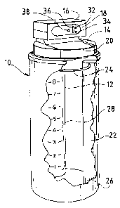
Referring to FIG. 1, this invention will be
described as embodied in a water softener wherein the water
softening system includes a salt container or tank 10 within
which is located within a resin tank 12. The salt storage
container 10 is provided with a cover 14 which supports a
housing 16 enclosing an electronic regeneration control
circuit. The front face of the electronic control circuit
housing 16 is provided with display and control panel 18. The
cover 14 includes a removable lid 20 which is provided
primarily for the purpose of permitting salt to be placed in
the salt storage container 10. The salt storage container 10
and the electronic control circuit are appropriately connected
by a tube and electrical conductors to the resin tank and an
electronically operated control valve respectively.
A brine well 22 is placed within the salt storage
container 10. Placed within the brine well is a conduit (not
shown) which extends to near the bottom of the salt storage
2128485
14528-678
8
container. A tube 24 connects the conduit to the appropriate
connection on the control valve. Openings 26 are provided at
the bottom of the brine well such that water may flow out of
the brine well and brine into the brine well. However, the
opening are sized such that solid particles, particularly
salt, are prevented from entering the brine tank.
Under the control of the electronic control circuit,
the control valve permits a predetermined amount of water to
flow through the tube 24, conduit, and openings 26 in the
brine well 22 into the brine tank. The flow of water into the
brine well 22 may also be terminated by a float valve
associated with the conduit and located in the brine well. As
demanded by the electronic control circuit, the control valve
is actuated to withdraw brine from the brine tank through the
openings 26 in the brine well 22, the conduit and the tube 24
by a venturi pumping action.
In accordance with the embodiment of this invention
shown in FIG. 1, indicia 26 are provided in association with
the brine tank or container in such a manner as to be readily
observable with respect to the top surface of the salt in the
tank by removing the lid 20. As shown in FIG. 1, the indicia
28 are integrally formed on the sidewall of the resin tank 12,
which is located within the salt storage container 10, in such
a position as to be readily visible when the lid 20 is
removed. The indicia 28 could, of course, be provided on the
sidewall of the resin tank 12 in other ways, such as by
2128485
14528-678
9
providing a separately formed measurement strip similar to a
ruler or yardstick, having the indicia 28 fonaed thereon,
which strip is secured to the sidewall of the resin tank 12.
While the indicia may be provided in many different ways, they
should, of course, be provided in a form which is not attacked
by the corrosive atmosphere resulting from the brine contained
within the tank. In the preferred embodiment of this
invention, the indicia 28 are spaced apart in a vertical
direction such that the space between adjacent indicia 1
through 9 represents one-tenth of the total salt capacity of
the tank.
Referring to FIG. 2, another embodiment of a water
softening system of this invention is shown in which the salt
storage container 10 is provided with a transparent or semi-
transparent window 30 having the indicia 28 formed thereon.
In the embodiment shown in FIG. 2, similar components are
identified by numerals corresponding to those applied to the
embodiment shown in FIG. 1. In this embodiment the indicia 28
are readily visible on the outside of the storage tank, as is
the salt level through the transparent window 30, such that it
is not necessary to remove the lid 20 to observe the salt
level and the indicia 28. While this embodiment may be more
convenient to use, it adds considerable to the cost of the
salt container 10.
FIG. 3 shows still another embodiment of this
invention wherein the indicia 28 are integrally formed on the
2128485
14528-678
inside surface of the brine tank 10, much as they were on the
resin tank 12 in FIG. 1. Again, the indicia could be provided
on a separately formed measurement strip similar to a ruler or
yardstick, having the indicia formed thereon, which is secured
5 to the inside wall of the salt container 10 in a position to
be readily observed when the lid 20 is removed.
This invention is also applicable to softeners in
which the salt container 10 is separated from the resin tank
12. Such a softener is shown in FIG. 4. As shown in FIG. 4,
10 the indicia are integrally formed on the inside surface of the
brine tank, much as they are in the embodiment shown in FIG.
3. However, they could also be provided as shown in FIG. 2.
Provided on the control panel of the softener
systems shown in FIGS. 1-4 are manual input means for
inputting salt levels as observed with respect to the indicia
28. Referring to FIGS. 1 through 4, the control manual input
means includes a salt increase key 32, a salt decrease key 34,
a salt level display 36, shown as a bar indicator, and an
alarm indicator 38, such as lighted indicator.
The operation of a water softener in accordance with
this invention will now be described by making reference to
the flow chart set forth in FIG. 5. Presuming that a quantity
of salt has just been added to the salt tank 10, the indicia
28 which is closest to the top surface of the salt should be
identified. The identified indicia may be the one that is just
visible above the top surface of the salt, or it may be the
2128485
14528-678
11
one just below the top surface of the salt. Whichever indicia
28 is considered to be most appropriate is entered into the
electronic control circuit by actuating either the salt
increase key 32 or the salt decrease key 34 until the salt
level display 36, indicates a salt level corresponds to the
salt level observed in the salt tank 10.
For instance, if after the addition of salt, the top
level of the salt is closest to the indicia indicating that
the tank is 80% full, the appropriate salt increase key 32 or
salt decrease key 34 is actuated until the salt level display
36 shows 80%. As set forth at 100 on the flow chart, if the
salt increase key 32 is pressed when the currently stored salt
level is not greater than 90%, the stored or displayed salt
level will be increased by 10%. If the currently displayed
salt level is greater than 90%, the displayed and stored salt
level is not changed.
When the salt level is again observed after a period
of use, and the salt level display 36 indicates a greater or
lesser amount of salt than that indicated by the observed
indicia 28, the salt increase key 32 or the salt decrease key
34 should be actuated to correct the salt level stored by the
electronic control circuit.
The functioning of the salt increase key 32 as set
forth at 100 in the flowchart has been described. As set
forth at 200 in the flowchart, if the salt decrease key 34 is
pressed when the salt level is not less than 10%, the stored
14528-678 212 ~ 4 8 5
12
or displayed salt level will be decreased by 10%. If the
currently displayed salt level is less than 10% the displayed
and stored salt level is not changed.
The electronic control circuit is designed to
actuate the alarm or low salt indicator 38 at a predetermined
minimum salt level. For instance, the predetermined minimum
salt level may be set at 30% as shown at 400 in the flowchart.
If the predetermined minimum salt level is set at 30%, and if
the salt level is equal to or less than 30% for more than one-
half second, the low salt indicator will be energized as
indicated at 500 and 600 in the flowchart. The low salt level
indicator will be turned off if the salt level is greater than
30% as indicated at 400 in the flowchart.
After brine has been used to regenerate the resin
bed, water will be added to the salt tank 10 at an appropriate
time and in an appropriate amount as controlled by the
electronic control circuit actuating the control valve, or by
a float valve as previously discussed. As set forth in the
flow chart at 700, if fill water is not added to the salt
tank, the displayed salt level will remain at its current
level. However, if fill water is being added to the salt tank
and more than one second has elapsed, as set forth at 800 in
the flow chart, the stored salt level will be decreased by the
amount of salt which will dissolve in the amount of fill water
which enters the salt tank in one second as set forth at 900
in the flowchart. When fill water has been added, and brine
14528-678 212 8 4 8 5
13
used over a period of time, presumably several regeneration
cycles, such that the displayed and stored salt level is
reduced to 30% or less, 400 on the flow chart, and more than
one-half second has elapsed, 500 on the flow chart, the low
salt indicator 38 will be actuated. While a low salt visible
or illuminated indicator is shown on the control panel, an
audible indicator may also be actuated.
After salt has been added to the salt tank 10, and
the actual salt level is entered into the electronic control
circuit by the increase or decrease keys, and brine has been
used for a period of time, that is several regeneration
cycles, the salt level display 36 may indicate a different
salt level than that observed by the indicia 28. If such is
the case, the increase or decrease keys may be used to enter
the observed salt level'in a recalibration mode whereby the
decrease in salt level set forth at 900 in the flowchart will
be corrected to correspond with actual amount dissolved.
Referring to FIG. 6, a portion of an electronic
regeneration control circuit in accordance with this invention
is shown. A microcomputer 40 includes a central processing
unit 42 and a salt level memory 44. Inputs to the central
processing unit include the salt increase key 32, the salt
decrease key 34, and fill water flow time 46. Outputs of the
central processing unit 42 as based on the information stored
in the salt level memory 44 are the salt level display 36 and
the low salt indicator 38. The operation of the circuit shown
14528-678
14
in FIG. 6 is in accordance with the flow chart of FIG. 5. It
should be understood that only those aspects of the electronic
regeneration control circuit directly relating to this
invention are shown in FIG. 6. The microcomputer 40 also has
other inputs, such as time of day, usage of processed water,
etc. and also additional outputs such as those controlling the
control valve.
It should be apparent to those skilled in the art
that what has been described is considered at present to be a
preferred embodiment of the apparatus for providing a
regenerant solution to a regenerable liquid treatment medium
bed. However, in accordance with the patent statutes, changes
may be made in the apparatus without actually departing from
the true spirit and scope of this invention. The appended
claims are intended to cover all such changes and
modifications which fall within the true spirit and scope of
this invention.