Note: Descriptions are shown in the official language in which they were submitted.
W O 93/17816 PCT/CA93/00097
~ ~ ~cTr~Tl~ToR FCR CONTINU W S CASTING MOCL~ 2~Z~3~jZ3 ~:
Technical Field of the Invention
This invention relates to an oscillator used in
continuous casting to move the water cooled mould to and fro
relative to the solidifying casting to prevent the casting from
sticking to the mould and causing surface defects in the cast
product. More particularly, the invention relates to a
continuous casting machine ir, which the cast product is guided
lO out of the mould in a curved path having a predetermined casting -~
radius so that the cast product may be withdrawn and trim~ed to
required lengths in a horizontal orientation. The os~ tor
according to the invention comprises both means to osci11ate the
mould and means to guide the mould along a curved path.
Background Art
In the past, moulds were mounted on a beam having a length
co~ s~on~l;ng to the radius of curvature and pivoted at the
centre of curvature. The mould was mounted on the other end of -~
20 the beam and moved with the beam during oscillation. The rather -~
long beam length involved and many ~echan;cal difficulties
encountered with chanqes in beam length, fatigue, an~ load on
the bearings were found to be impractical.
The aforementioned problems were at least parts
addressed by the adoption of short levers provided in pairs and
co~e~Ling the mould to an external support disposed between the
mould and the centre of curvature. The short levers were
i~clined relative to each other and aligned to the centre of the
casting arc. This i,l~o~ nt in the art is well described in
U.S. Patent No. 3,343,592 to Yogel. Because the reciprocating
movem2nt of the mould is very short (O.OS0 to 0.5 in) the
deviation of the short lever travel from the casting arc is very
small and the mould movement along the casting radius is
acceptable. However, the pin joints of this design introduce
some ~ P~irable clearances which have to be carefully
controlled to make the method practical. The operating
conditions of a casting plant, including extre~ely high
temperatures, moisture, and abrasive su~stances in the
W O 93/17816 PC~rtCA93/00097
Z1~3623 - 2 -
atmosphere make the oscillator highly maintenance intensive.
In U.S. 4,456,052 to Takashi Kawakami, the short lever
design is improved by introducing a hydraulic cylinder which
compensates for bearing clearances.
The present tendency is to increase the frequency of
continuous casting moulds and permit frequencies of up to 400
cylces per minute. This requirement has lead to completely new
designs using a multitude of eccentrics as in U.S. 4,480,678 to
Cazaux et al While this is an improvement, it is a high cost
mechanically complex apparatus requiring carefully controlled
maintenance. Some proposals have been made to use leaf springs
in this field, as in U.S. 3,664,409 to Kolomeitsev et al and DE
3 000 117 to Sack, these springs are disposed in a ~anner which
subjects them to both co~pressive and tensile forces. They are
thus limited in their application to situations where the
buckling load of the leaf spring cannot be exceeded and thus are
of limited use.
The object of this invention is to address the
aforementioned problems described with reference to the prior
art, namely to simplify the construction of the ~ould oscillator
and to produce a high frequency oscillation which is stable and
maintenAnce free.
Disclosure of the Invention
In accordance with one aspect of this invention, there
is provided an improved mould guidance means forming part of a
~ntinuous casting machine in which a chilled mould is
oscillated in a curved path corresponding to a predetermined
casting radius. The mould is guided by a first tensile element
3G having an inner end and an outer end, the outer end being
anchored to a fixed external fra~e and the inner end being
secure to move with the mould, the first tensile ele~ent lying
on a first radius extending from the centre of curvature of the
predeter~ined casting radius. A second tensile ele~ent having
an inner and an outer end both anchore~ to a fixed external
frame is secured to mave with the mould at a point intermediate
~he inner and outer ends. At least one end of the second
tensile element has variable tensionin~ means adapted to apply a
W O 93/17816 PCT/CA93/00097
3 21;~
tensile force to the element so as to prestress the element
prior to oscillation. The second tensile element lies in a
second radius extending from the centre curvature of the
predetermined casting radius.
In accordance with another aspect of this invention,
the oscillating drive comprises drive means, cam means coupled
to the drive means for rotation in a vertical plane and having a
predetermined eccentricity, follower means pivotable at one end
about a pivot mounted to a fixed external frame and adapted to
maintain physical contact with the c2m means, transfer means
disposed to maintain contact between the follower means and the
mould table, and selection means adapted to adjust the distance
separating the wheel from the pivoted end of the follower so as
to vary the oscillation stroke imparted to the ~ould.
Description of the Drawings
A preferred emkodiment of the ~nvention is described
below with reference to the acco~panying drawings, in which:
Fig. l is a partly sectioned side elevation of a
continuous casting machine made according to the invention;
Fig. 2 is a plan view looking down on line 2-2 of Fig.
l (drawn to a larger scale);
Fig. 3 is a plan view looking down on line 3-3 of Fig.
l (drawn to a larger scale~;
Fig. 4 is an enlarged detail view of variable
tensioning means;
Fig. 5 is a side eleva~ional view taken on line 5-5 of
Fig. l (drawn to a larger scale);
Fig. 6 is a top elevational view on arrow 6 from Fig. l
(drawn to a larger scale);
~ igs. 7-9 are sch~ tic views s;~;lAr to Fig. 5 showing
an os~ ation drive with cam means in a variety of positions
relative to a follower and corresponding to an oscillation
stroke of n~;nA1 magnitude, a stroke of smaller magnitude, and
a stroke of larger magnitude, respectively; and
Figs. lO and ll are schematic side elevations similar
to Fig. 1 showing the relative displ~cP~nt of a mould and
associated tensile elements during the upward stroke of the
W O 93/17816 PC~r/CA93/00097
t C
~Z8GZ3 - 4 -
oscillating drive and the downward stroke, respectively.
Best Mode for Carrying out the Invention
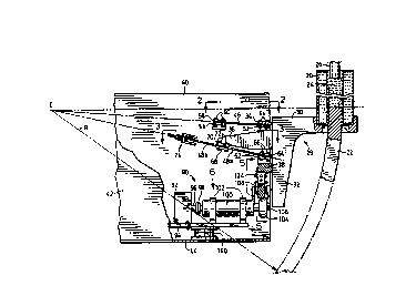
; Referring firstly to Fig. l, there is shown a continuous casting' 5 machine comprising a water cooled mould 20 of which the inner
; walls have a slight curvature as is now common in the art so as
to precurve a cast bar 22 emerging fro~ the ~ould 20 at the
~ bottom thereof and being continuously supplied from a pool of
mould metal 24 contained at the top of the mould and fed by a
tun~ish 26 or other conventional means. The cast bar 22 is
guided along a predetermined curved path by conventional means
including starter bars and rollers (not shown), the path having
~n inner radius of curvature designated by the letter R and
having a centre of curvature C.
The mould 20 is supported on a ~ould table generally
indicated by numeral 28 and comprising a generally horizontal
platform 30, a downwardly extending leg portion 32, a lug 34
extending across the width of the platform 30 transversely to
- the ~ownward portion 32 and a pair of extensions 36 extending
transversely to the downward portion 32 and disposed below the
' lug 34. The extensions 36 are spaced from one another in
parallel and ~isp~sed on the same side of the mould table 28. A
bracket 38 extends outwardly from the downward portion 32 and is
~;.cposed below the extensions 36.
An osc;1l~ting drive and mould guidance means is ho~sed
in a fixed external frame having a rear wall 40 as drawn in Fig.
l~ a partly cutaway front wall 42 and a floor 44. The mould 20
and A~soci~ted mould table 28 are connected to the frame by
tensile elements 46, 48a, 48b and 50a, 50b (Fia. 3) anchored at
their free end to the fixed frame and each lying in a respective
,'.! radius extending from the centre of curvature C.
~ The first tensile element 46 has its inner end
'- sandwiched between the lug 34 and a plate 52 and is secured with
suitable fasteners 54. The outer end of the first tensile
element 46 is similarily sandwiched between a bracket 56
extending between the rear wall 40 and the front wall 42 of the
fixed frame and a plate 58 likewise secured by suitable
fasteners 60. As can more clearly be seen in Fig. 2, the first
~
W O 93/17816 PC~rtCA93/00097
-
21;~8623
element 46 comprises a sheet of rectangular shape which extends
substantially across the width of the platform 30 comprising the
mould table 28. Preferably, it is constructed fro~ stainless
spring steel material which is precipitation hardened.
The second tensile element 48 ~omprises two lenqths 48a
and 48b of stainless spring steel, each having an end anchored
to the fixed external frame and of which the other end is
attached to a common mount at the free end of one of the
extensions 36. Conveniently, the lengths may be deemed to
comprise a single tensile element of which both the inner and
outer ends are anchored to the fixed external frame. Th~s the
length 48a of the second tensile element has one end sandwiched
between a bracket 62 extending transversely from the rear w311
40 toward the front wall 42 and a plate 64 secured by suit:able
fasteners 66. The other end of the length of 48a comprising the
se~nd tensile element 48 is secured to move with the mould 20
and is sandwiched between a lug 68 for~ing part of the extension
36 and a plate 70 secured by a suitable fastener 72. The length
48b comprising the other end of the second tensile element 48 is
likewise secured to the mould extension 36 by a respective
fastener 72 transversing the plate 70 and lug 68. At the other
end, the length 48b is secured to variable tensioning means
generally indicated by numeral 74 anchored to the rear wall 40
of the fixed external fr~me.
The variable tensioning means 74 is shown in greater
detail in Fig. 4. The second element 48 is held in a shackle 76
by a through pin 78 shown in ghost-outline. The shackle 76 is
~;srosed inside a guide 80 of substantially C-shaped cross
section and secured to a bracket 82 extending from the rear wall
40 of the external frame towards the front wall 42. A threaded
rod 84 is received in an opening provided through the bracket 82
and guide 80 and is held captive in the shackle 76. A plurality
of Belville spring washers 86 located about the rod 84 and
interposed between the bracket 82 and an adjustment nut 88
operate to apply a load on the shackle 76 and Frestress the
second tensile element 48. The tension imFarted to the length
48b of the second tensile element 48 may be adjusted as required
by varying the position of the retaining nut 88 on the rod 84.
~, . . . . . . . .
W O 93/17816 PC~r~CA93/OOOg7
, .,.~ c
z~'~86~3 - 6 ~
As indicated above, the mould extension 36 is provided
in pairs each associated with a respective second tensile
element 48, 59. The attachment of the second tensile element 50
to the fixed external frame and to the mould table 28 is
analogous to the atta~hmPnt of the second tensile element,48 and
like parts are identifed by like numerals in the drawings. It '
will of course be understood that the brackets 62 and 82
associated with the second tensile element 50 extend from the
front wall 42 toward the rear wall 40 of the fixed external
frame.
The oscillating drive generally indicated by numeral 90
in Fig. 1 will now be described with reference being made in
particular to Figs. 5 and 6. The oscillating drive co~prises
drive means including a motor (not s~own) mounted in a housing
92 and suppor~ed on a table 94, a drive shaft 96 driven by the
motor, and a coupling 98 coupling the drive shaft 96 to a
reinforced shaft 100. The gear box 100 is supported on the
table 94 by a pair of longitudinally spaced pedestals 102. An
eccentrically driven wheel or cam 104 is rotatably driven for
rotation in a vertical plane with a driven shaft 106 coupled to
the shaft 100. A follower 108 in the form of a bar is pivotably
~ounted at one end for rotation about a pivot pin 110 fixed to a
bracket 112 extending from the rear wall 40 of the fixed
external frame toward the front wall 42. A leaf spring 114 is
secured to the free end of the follower 108 remote from the
pivot 110 by means of suitable fasteners 116 which penetrate the
leaf spring and an overlying plate 118. The leaf spring 114 is
also secured to the front wall 42 of the fixed external frame
with fasteners 120 which penetrate the leaf spring and an
overlying plate 122. The leaf spring 114 thus biases the
follower 108 toward the wheel 104.
A transfer means 124 in the form of a rocker is
disposed between the follower 108 and the bracket 38 extending
from the downward portion 32 of the mould table 28. The
transfer means 124 is secured to the bracket 38 by another leaf
spring 126 attached at r~spective ends to the bracket 38 and the
transfer means 124 by fasteners 128 and 130 each associated with
a respective plate 132 and 134. The transfer element 124
W O 93/17816 P ~ ICA93/00097
''- Z'1.;~86
-- 7 --
carries a pair of spaced apart outwardly extending pins 136 each
of which locates in a ~lot formed in plates 138 attached to the
mould bracket 38 and the follower lOB in alignment with one
another.
The table 94 is rotatably mounted on a turnta~le 140.
The radial position of the table 94 on the turntable 140 is
determined by selection means generally indicated in Fig. 6 by
numeral 142. The selection means 142 comprises an adjustable
tie secured at one end to the table 94 and at the other end to
the front wall 42 of the fixed external frame. The tie is in
the form of a threaded rod 144 fixed at one end to a ~racket 146
attached to the table 94. The threaded rod 144 is receiv~
through a pinion 148 having a complementary female thread and
whose axial position on the rod 144 is adjusted with a worm 150
15 attached to a bracket 152 forming part of the front wall 42 of
the fixed external frame.
It will be appreciated that adjusting the effective
length of the threaded tie rod 144 by means of the wor~ 150 will
vary the radial position of the table 94 along an arc indicated
by arrows 154. As a result, the radial position of the wheel
- 104 or cam on the turntable can be selected. In Fig. 6,
alternate positions of the wheel 104 are drawn in ghost-outline
and show the wheel either close to the pivot 110 of the follower
108 or remote fro~ the pivot.
In Figs. ~ to 9, it is illustrated how the oscillation
stroke imparted to the ~ uld will vary according to whether the
wheel 104 or cam is positioned in align~ent with the transfer
means 124 and about ~idway between the ends of the follower 108
~Fig. 7); spaced from the transfer means 124 and remote from the
30 pivot 110 (Fig. 8); and spaced fro~ the transfer means 124 but
near the pivot 110 (Fig. 9). In the neutral position shown in
Fig. 7, the follower 108 will travel through a vertical height
of magnitude XO which corresponds to the eccentricity of the
wheel 104 and the mould 20 will likewise have an oscillation
stroke of magnitude XO. In Fig. 8 where the wheel 104 is
remote from the pivot 110, the vertical displace~ent of the
follower 108 at the transfer means 124 has a magnitude Xl
which is less than the eccentricity XO of the wheel 1~4. The
W O 93/17816 PCT/CA93~00097
6~3 - 8 -
oscillation stroke of the mould likewise has a smaller magnitude
Xl. In Fig. 9 where the wheel 104 is near the pivot llO, the
vertical displacement of the follower 108 at the transfer means
124 has a magnitude X2 which is larger than the eccentricity
Xl of the wheel. Si~ rly, the oscillation stroke of the
mould 20 has a greater magnitude X2.
It will thus be understood that the oscillation stroke
of the mould may be varied simply by rotation of the table 94
and this is easily accomplished while the continuous casting
machine is in operation. This permits the stroke to ~e adjusted
in situ in accordance with the oscillation frequency and casting
speed for better cvntrol of the surface finish of the cast bar
22.
In the upstroke of the follower 108 during oscillation,
the mould table 28 is brought to an upwardly inclined position
illustrated in Fig. lO. The first tensile element 46 operates
to ~ecure the mould table 28 to the fixed external fra~e and
limits the J~ cr~t of the mould table along a line which is
perpendicular to the associated first radius extending from the
centre of curvature C. Similarly, the second tensile elements
48, 50 limit m~ nt of the mould table 28 along a line which
is perpendicular to the associated second radius extending fro~
the centre of curvature C. The result is that the mould table
28 is guided around the centre of curvature on the castina arc.
It will be appreciated that the actual ~ nt about the
tensile elements is along an arc defined by the length of the
tensile element but since the ratio of the length of the tensile
elements to the stroke is in the order of 200 to l, the
deviation from a circular arc of a straight line is negliqikle
and within the expected elastic tolerances of the oscillator.
It will be noted that the first tensile element 46 is a
sheet which will flex quite easily in a direction transverse to
the A-csociated first radius but which will be totally rigid in
the orthogonal direction across the width of the mould table
28. This design feature gives the mould table a most important
lateral stability. Whether the mould table 28 is in the
upwardly i~Cli~e~ position on the upward stroke of the
os~ tion movement as shown in Fig. lO or in a downwardly
W O 93/17816 PC~r/CA93/00097
- 9- 21;~8~
incline~ position as shown in Fig. ll on the downward stroke of
the oscillation moYement, the first tensile element is always
maintained in tension.
The second tensile elements 48, 50 are maintained in
tension by applying a ~reload using the adjustment nut 88. The
Belville spring washers 86 operate to change the effective
length of the second tensile elements 48, 50 during
osc;ll~tion. Since the length changes are very small, in the
order of 0.005 inches, the length changes in the second tensile
elements may in part be accomcdated by the elastic behaviour of
the spring steel material comprising the elements. It will be
appreciated that the prestressed second elements 48, 50 will
firmly locate the mould table 28.
An analysis of the mechanical forces operating on the
mould table will show a clockwise turning mo~ent (as drawn)
defined by the combined mass of the mould 2Q and mould table
28. The count~rclockwise moment originates in the tensile
forces applieZ to the first and second tensile elements.
~eca~qe the second tensile ele~ents are anchored at their free
ends to the fixed external frame, the connection to the mould
table being established intermediate those ends on the mould
extensions 36, the second tensile elements 48, 50 are likewise
maintained in tension. Any compressive forces applied to the
second tensile elements 48 are nullified by prestressing the
elements with the tensioning means 74.
Typically, the oscill~tion stroke achieved will vary
between 0.05 inches and 0.5 inches at an oscillation frequency
of 400 to 40 cycles per minute respectively and will vary as a
function of casting speed.
Industrial Applicability
The invention thus provides an elegantly si~ple
structure for controlling movement of a mould table without any
- slop heCAllce no clearances are required betwecn relatively
moving parts. The apparatus is expected to be long lasting and
operate maint~nAnce free as long as the tensile elements are
used at stress levels which do not exceed their fati~ue
resistance~ It is expected that the load carrying capacity of
W O 93/17816 P ~ fCA93/00097
2128623 . - lo - ~
~ ~ '. ;t ? i' ~ ~ 7
the mould table will be greatly enhanced because tensile members
are employed.
Moreover, the oscillation stroke may be adjusted in
situ thereby greatly facilitating the selection of optimium
5 operating conditions.
It will be appreciated that several variations may be
made to the above described preferred embodiment of the 3
invention without departing from the scope of the ~y~ended
claims. As will be apparent to those skilled in the art, the
mould guidance means comprising the tensile elements may be
a~soriAted with a co1l~entional oscillating drive including
variety of eccentrically driven means and reciprocating
cylinders of various kin2s.
In the preferred embodiment described above, an
lS eccentric wheel oscillates a follower pivoted at one end and the
distance separating the wheel from the pivoted end is varied by
mounting the wheel on a turntable. It will of course ke
acceptable to move the wheel linearly relative to the follower
by mounting it for example on a table supported on rails
comprising a rack and pinion.
It will also be appreciated that the oscillating drive
may be positioned outside the radius of curvature of the cast
product exiting the mould, in which case the tensile elements
may be rearranged so as to remain in tension.
W O 93/1781~ PC~r/CA93/00097
Index o~ Reference Signs 2128623
mould 82 bracket
~2 cast bar 84 threaded rod
5 24 molten metal pool 86 Belville washers
26 turndish 88 adjustment nut
28 mould table 90 oscillating drive
platform 92 motor housing
32 mould table 94 table
(downward position) 96 drive shaft
34 lug 98 coupling
36 mound table 100 gearbox
(extension) 102 pedestal (2)
38 bracket 104 (cam) wheel
fixed frame 106 drive shaft
(rear wall) 108 follower
42 fixed frame 110 pivot
(front wall) 112 bracket
44 fixed frame (floor) 114 leaf spring
46 first tensile element 116 fasteners
48a.b second tensile elements 118 plate
50a.b second tensile elements 120 fasteners
52 plate 122 plate
54 fasteners 124 transfer means
56 bracket 126 leaf spring
58 plate 128 fasteners
fasteners 130 fasteners
62 bracket 132 plate
64 plate 134 plate
66 fasteners 136 pins
68 lug 138 plates (slotted) (2)
plate 140 turntable
72 fasteners 142 selection means
74 tensioning means 144 threaded rod
76 shackle 146 bracket
78 pin 148 pinion
guide 150 worm
82 bracket 152 bracket
154 arrows
c~r~:TIT~IT F ~ Fr~lr