Language selection

Search

Patent 2128874 Summary

Third-party information liability

Some of the information on this Web page has been provided by external sources. The Government of Canada is not responsible for the accuracy, reliability or currency of the information supplied by external sources. Users wishing to rely upon this information should consult directly with the source of the information. Content provided by external sources is not subject to official languages, privacy and accessibility requirements.

Claims and Abstract availability

Any discrepancies in the text and image of the Claims and Abstract are due to differing posting times. Text of the Claims and Abstract are posted:

  • At the time the application is open to public inspection;
  • At the time of issue of the patent (grant).
(12) Patent: (11) CA 2128874
(54) English Title: CONTROL ARM ARRANGEMENT FOR A BRAKE LEVER
(54) French Title: LEVIER DE COMMANDE DE FREIN
Status: Expired and beyond the Period of Reversal
Bibliographic Data
(51) International Patent Classification (IPC):
  • F16D 65/28 (2006.01)
  • F16D 65/22 (2006.01)
  • F16D 65/60 (2006.01)
(72) Inventors :
  • NELANDER, AKE (Sweden)
(73) Owners :
  • HALDEX AB
(71) Applicants :
  • HALDEX AB (Sweden)
(74) Agent: SMART & BIGGAR LP
(74) Associate agent:
(45) Issued: 2004-04-13
(86) PCT Filing Date: 1993-02-03
(87) Open to Public Inspection: 1993-08-19
Examination requested: 1999-09-10
Availability of licence: N/A
Dedicated to the Public: N/A
(25) Language of filing: English

Patent Cooperation Treaty (PCT): Yes
(86) PCT Filing Number: PCT/SE1993/000081
(87) International Publication Number: WO 1993016429
(85) National Entry: 1994-07-26

(30) Application Priority Data:
Application No. Country/Territory Date
9200317-7 (Sweden) 1992-02-05

Abstracts

English Abstract


A control arm arrangement for a road vehicle brake lever having a control arm
pivotally connected to the brake lever and an anchor bracket for attachment to
an
underframe part of the vehicle. The control arm comprises a first U-shaped
flange
with facing ends and the anchor bracket comprises a second U-shaped flange
with
facing ends that fit closely with facing ends of said first U-shaped flange.


Claims

Note: Claims are shown in the official language in which they were submitted.

THE EMBODIMENTS OF THE INVENTION FOR WHICH AN EXCLUSIVE
PRIVILEGE OR PROPERTY IS CLAIMED ARE DEFINED AS FOLLOWS:
1. A control arm arrangement for a road vehicle brake lever having a control
arm
with a first end pivotally connected to the brake lever and an anchor bracket
with
a first end for attachment to an underframe part of a vehicle; said control
arm
comprising a first U-shaped flange at its second end and said anchor bracket
comprising a second U-shaped flange at its second end, said first U-shaped
flange
overlapping said second U-shaped flange to produce a contact area between said
first and second U-shaped flanges wherein vibrations and forces between said
brake lever and the vehicle are withstood with minimal wear.
-5-

Description

Note: Descriptions are shown in the official language in which they were submitted.


CA 02128874 2002-05-16
A CONTROL ARM ARRANGEMENT FOR A BRAKE LEVER
Technical Field
This invention relates to a control arm arrangement for a road vehicle brake
lever, comprising a control arm pivotally connected to the brake lever and an
anchor
bracket for attachment to an underframe part of the vehicle.
1o Background of the Invention
A conventional brake lever for a heavy road vehicle is mounted on an S-cam
shaft of a drum brake and is connected to a brake cylinder, as is well known
in the art.
It contains an automatic slack adjuster, which for its function needs a
control signal,
provided by a control arm connected to a fix-point on the vehicle, normally by
means
of an anchor bracket.
Conventionally, the control arm and the anchor bracket are connected by
means of a screw joint, containing a washer and possibly a wear-reducing
plastic
2o insert. At mounting the corresponding holes in the two parts have to be
aligned and
the screw joint (screw and nut) securely fastened. Due to vibrations and
mutual
movements it is difficult to obviate wear and noise. The screw joint may also
give
difficulties at later dismounting.
Another possibility is to provide the anchor bracket with a slot for
cooperation
with a suitably shaped end of the control arm. The cooperating contact
surfaces are
small, which means that the problem with wear is not obviated, even if the
mounting
difficulties are decreased.
-1-

CA 02128874 2003-05-16
Summary of the Invention
A far better solution is according to the invention attained in that facing
ends of
the control arm and the anchor bracket are provided with flanges, so that the
closely
cooperation ends are U-shaped in cross-section.
The arrangement is extremely easy to mount and dismount, three are no
connection means and the contact area between the cooperating parts is very
large, which
means that the wear will be minimal, even if the arrangement is subjected to
vibrations
t o and big forces.
As embodied and broadly described herein, the invention provides a control arm
arrangement for a road vehicle brake lever having a control arm with a first
end pivotally
connected to the brake lever and an anchor bracket with a first end for
attachment to an
underftame part of a vehicle; said control arm comprising a first U-shaped
flange as its
second end and said anchor bracket comprising a second U-shaped flange at its
second
end, said first U-shaped flange overlapping said second U-shaped flange to
produce a
contact area between said first and second U-shaped flanges wherein vibrations
and
forces between said brake lever and the vehicle are withstood with minimal
wear.
Brief description of the Drawings
The invention will be described in further detail below reference being made
to
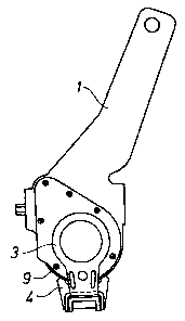
the accompanying drawings, in which Fig 1 is a side view of a road vehicle
automatic
brake lever with a control arm arrangement according to the invention, Fig 2
is an end
view of the same arrangement, whereas Figs 3 and 4 to a larger scale and in
views
corresponding to those according to Figs 1 and 2, respectively, show the two
parts
relevant to the invention.
_Z_

i.
CA 02128874 2002-05-16
In the drawings, the preferred embodiment of the invention is illustrated by
way of examples. It is to be expressly understood that the description and
drawings
are only for the purpose of illustration and are an aid for understanding.
They are not
intended to be a definition of the limits of the invention.
Detailed Description of a Preferred Embodiment
A conventional brake lever containing an automatic slack adjuster has the
numeral 1. As is well known in the art and accordingly not shown, such a lever
is
1o mounted on an S-cam shaft for a drum brake of a heavy road vehicle and is
connected
to a brake cylinder push rod.
A brake lever 1 of this kind, which in operation is rocking about its shaft at
each brake application and release, needs a fixed reference point for its
internal slack
adjusting mechanism. This reference point may, as shown in Fig 2, be an
underframe
part 2, which is also used for journaling the S-cam brake shaft (not shown).
The arrangement for connecting the brake lever 1 with the underframe part 2
consists of two details, namely a control arm 3 and an anchor bracket 4. The
control
2o arm 3 is pivotally connected to the brake lever 1 in order to transmit a
control signal
to internal parts thereof, whereas the anchor bracket 4 is connected to the
underframe
part 2 by means of at least one screw joint 5 in an oblong hole 6 in the
anchor bracket
4 so as to allow position adjustments.
The control arm 3 may be provided with stiffening ribs 7 in the plate material
and a hole 8 for access to screws 9, which would otherwise be covered. The
lower part
of the control arm 3 is bent at a right angle and is there provided with
flanges 10 so as
to have a U-shape in cross-section.
-3-

i
CA 02128874 2002-05-16
In a corresponding way the end of the anchor bracket 4 is bent and is provided
with flanges 11 so as also to have a U-shape in cross-section. The
dimensioning is
such that relative axial movements between the two U-shaped ends are possible
but
that they fit together rather closely side-ways. In this way a very large
contact area
between the two cooperating parts is obtained with a resulting minimal wear.
The
arrangement is easy to install, and there are no holes, screws, nuts, washers
or inserts
as in the arrangement it is to replace.
The above description of the preferred embodiment should not be interpreted
1o in a limiting manner since other variations, modifications and refinements
are possible
within the spirit and scope of the present invention. The scope of the
invention is
defined in the appended claim and its equivalents.
-4-

Representative Drawing
A single figure which represents the drawing illustrating the invention.
Administrative Status

2024-08-01:As part of the Next Generation Patents (NGP) transition, the Canadian Patents Database (CPD) now contains a more detailed Event History, which replicates the Event Log of our new back-office solution.

Please note that "Inactive:" events refers to events no longer in use in our new back-office solution.

For a clearer understanding of the status of the application/patent presented on this page, the site Disclaimer , as well as the definitions for Patent , Event History , Maintenance Fee  and Payment History  should be consulted.

Event History

Description Date
Inactive: IPC deactivated 2012-01-07
Inactive: First IPC from PCS 2012-01-01
Inactive: IPC from PCS 2012-01-01
Inactive: IPC expired 2012-01-01
Time Limit for Reversal Expired 2009-02-03
Letter Sent 2008-02-04
Inactive: IPC from MCD 2006-03-11
Grant by Issuance 2004-04-13
Inactive: Cover page published 2004-04-12
Inactive: Final fee received 2004-01-07
Pre-grant 2004-01-07
Letter Sent 2003-07-24
Notice of Allowance is Issued 2003-07-24
Inactive: Approved for allowance (AFA) 2003-07-11
Amendment Received - Voluntary Amendment 2003-05-16
Inactive: S.30(2) Rules - Examiner requisition 2003-04-01
Amendment Received - Voluntary Amendment 2002-05-16
Inactive: S.30(2) Rules - Examiner requisition 2001-12-07
Inactive: Status info is complete as of Log entry date 1999-10-04
Letter Sent 1999-10-04
Inactive: Application prosecuted on TS as of Log entry date 1999-10-04
All Requirements for Examination Determined Compliant 1999-09-10
Request for Examination Requirements Determined Compliant 1999-09-10
Application Published (Open to Public Inspection) 1993-08-19

Abandonment History

There is no abandonment history.

Maintenance Fee

The last payment was received on 2004-01-19

Note : If the full payment has not been received on or before the date indicated, a further fee may be required which may be one of the following

  • the reinstatement fee;
  • the late payment fee; or
  • additional fee to reverse deemed expiry.

Please refer to the CIPO Patent Fees web page to see all current fee amounts.

Fee History

Fee Type Anniversary Year Due Date Paid Date
MF (application, 5th anniv.) - standard 05 1998-02-03 1998-01-29
MF (application, 6th anniv.) - standard 06 1999-02-03 1999-01-25
Request for examination - standard 1999-09-10
MF (application, 7th anniv.) - standard 07 2000-02-03 2000-01-24
MF (application, 8th anniv.) - standard 08 2001-02-05 2001-01-12
MF (application, 9th anniv.) - standard 09 2002-02-04 2002-01-25
MF (application, 10th anniv.) - standard 10 2003-02-03 2003-01-29
Final fee - standard 2004-01-07
MF (application, 11th anniv.) - standard 11 2004-02-03 2004-01-19
MF (patent, 12th anniv.) - standard 2005-02-03 2005-01-28
MF (patent, 13th anniv.) - standard 2006-02-03 2006-01-23
MF (patent, 14th anniv.) - standard 2007-02-05 2007-01-17
Owners on Record

Note: Records showing the ownership history in alphabetical order.

Current Owners on Record
HALDEX AB
Past Owners on Record
AKE NELANDER
Past Owners that do not appear in the "Owners on Record" listing will appear in other documentation within the application.
Documents

To view selected files, please enter reCAPTCHA code :


To view images, click a link in the Document Description column. To download the documents, select one or more checkboxes in the first column and then click the "Download Selected in PDF format (Zip Archive)" or the "Download Selected as Single PDF" button.

List of published and non-published patent-specific documents on the CPD .

If you have any difficulty accessing content, you can call the Client Service Centre at 1-866-997-1936 or send them an e-mail at CIPO Client Service Centre.


Document
Description 
Date
(yyyy-mm-dd) 
Number of pages   Size of Image (KB) 
Representative drawing 1998-07-27 1 4
Description 2003-05-16 4 139
Claims 2003-05-16 1 19
Representative drawing 2003-07-11 1 4
Claims 2002-05-16 1 15
Abstract 2002-05-16 1 12
Description 2002-05-16 4 137
Drawings 2002-05-16 3 26
Cover Page 1995-08-19 1 17
Abstract 1995-08-19 1 42
Claims 1995-08-19 1 14
Description 1995-08-19 3 142
Drawings 1995-08-19 2 28
Cover Page 2004-03-10 1 31
Acknowledgement of Request for Examination 1999-10-04 1 193
Commissioner's Notice - Application Found Allowable 2003-07-24 1 160
Maintenance Fee Notice 2008-03-17 1 172
PCT 1994-07-26 7 244
Correspondence 2004-01-07 1 21
Fees 1997-03-12 1 34
Fees 2004-01-19 1 40
Fees 1997-02-11 2 65
Fees 1995-01-23 1 61
Fees 1996-01-30 1 59