Language selection

Search

Patent 2129164 Summary

Third-party information liability

Some of the information on this Web page has been provided by external sources. The Government of Canada is not responsible for the accuracy, reliability or currency of the information supplied by external sources. Users wishing to rely upon this information should consult directly with the source of the information. Content provided by external sources is not subject to official languages, privacy and accessibility requirements.

Claims and Abstract availability

Any discrepancies in the text and image of the Claims and Abstract are due to differing posting times. Text of the Claims and Abstract are posted:

  • At the time the application is open to public inspection;
  • At the time of issue of the patent (grant).
(12) Patent: (11) CA 2129164
(54) English Title: BINGO DABBER
(54) French Title: MARQUEUR DE BINGO
Status: Expired and beyond the Period of Reversal
Bibliographic Data
Abstracts

English Abstract


A bingo dabber has an inner end with
attachment means for a finger and an outer end with a
tank connected to feed a dabber tip.


French Abstract

La présente invention a pour objet un tampon destiné aux jours de bingo comportant un dispositif de fixation au doigt, et dont une extrémité est pourvue d'un réservoir de liquide pour alimenter le tampon.

Claims

Note: Claims are shown in the official language in which they were submitted.

The embodiments of the invention in which an exclusive property
or privilege is claimed are defined as follows:
1. Bingo dabber comprising:
a body defining an inner end,
means at said inner end for detachable mounting on an
outer extent of a finger,
said body being shaped to define an outer end generally
directed away from said finger when so attached,
said body defining a tank intermediate said inner and
outer end,
a passage connecting said tank to said outer end, open
cellular material filling said passage,
said material being shaped to form an outwardly facing
dabber.
2. Bingo dabber as claimed in claim 1 wherein said body is
shaped to define a body extent, slightly downwardly directed
relative to said finger extent, when so detachably attached,
and the hand corresponding to said finger is held palm downwardly.
3. Bingo dabber as claimed in claim 1 wherein, said means
for detachable attachment comprises:
an inwardly directed recess defined on said body adapted to
receive the finger tip corresponding to said finger extent, and
means for resilient attachment of said body to said extent
when said finger tip is received in said recess.
4. Bingo dabber as claimed in claim 1 wherein said detachable
attachment means includes an upwardly open channel for receiving
said outer finger extent, and
- 5 -

a pair of resilient members one extending upwardly from each
side of said channel and shaped to press on said finger extent when
the latter is contained in said channel.
5. Bingo dabber as claimed in claim 2 wherein said detachable
attachment means includes an upwardly open channel for receiving
said outer finger extent, and
a pair of resilient members one extending upwardly from each
side of said channel and shaped to press on said finger extent when
the latter is contained in said channel.
6. Bingo dabber as claimed in claim 3 wherein said means for
resilient attachment includes an upwardly open channel for receiving
said finger extent when said tip is received in said recess, and
a pair of resilient members, one extending upwardly from each
side of said channel and shaped to press on said finger extent when
the latter is contained in said channel.
7. Bingo dabber as claimed in claim 4 wherein said means for
resilient attachment includes an upwardly open channel for receiving
said finger extent when said tip is received in said recess, and
a pair of resilient members, one extending upwardly from each
side of said channel and shaped to press on said finger extent when
the latter is contained in said channel.
- 6 -

Description

Note: Descriptions are shown in the official language in which they were submitted.


212916g
This invention relates to a bingo dabber, that is a hand held,
ink marking device, for marking squares on bingo cards.
Heretofore bingo dabbers known to me have been relatively thick
cylinders of the general contour of the common felt pen but slightly
thicker. Such prior dabbers are somewhat cumbrous to carry and use
and specifically require holding, in use by the user's palm and
fingers.
I have designed a bingo dabber which is more compact and
convenient shape and more convenient to use.
The inventive dabber provides a body, designed adjacent the
inward end, for detachable attachment to an outer extent of a finger,
and shaped to define an outer end. The body when so attached defines
a tank outwardly of said fingers and preferably provides closable
entry means for refilling said tank, where the body defines a passage
at its finger-remote end with resilient connected cellular material
filling the passage and forming an outwardly directed dabber tip.
The invention therefore provides a dabber which does not require
a voluntary holding action but is resiliently attached to the user's
finger and, while so attached, conveniently oriented for use by the
equivalent of a tapping motion of the finger.
(This will usually be the index finger).
Preferably the body is shaped to define a body extent extending
between said attachment means and said dabber tip which is shaped
to be slightly downwardly directed relative to said finger extent.
This increases the convenience with which a dabber is used with a
tapping motion.
Preferably the mef~ns for detachable attachment comprises an
upwardly open channel, an inwardly facing recess facing the outward

2129164
end of said channel, shaped to snugly receive the tip of a finger
whose tip is received in said recess and a pair of resilient
members, one extending upwardly on each side of said channel,
shaped to partially close over said extent when the finger tip is
in said recess.
It is within the cope of the invention to make the cellular
~aterial removable, to use its passage as a filling port (after
first directing the dabber upwardly) so that the entry means and
the passage are combined. However, this arrangement is somewhat
inconvenient and tends to stain the user's hands. Thus, it is
found preferable to have a separate, closable, entry means upwardly
directed when the dabber is in its normal orientation, on the finger
of a hand held palm downwardly, (i.e. in the normal orientation for
the dabber).
In drawings which illustrate a preferred embodiement of the
invention:
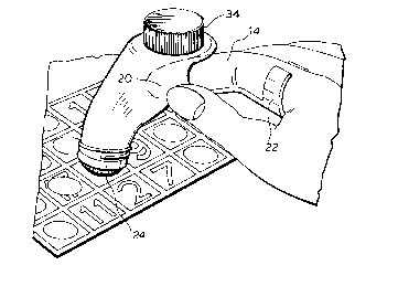
Figure 1 is a persepective of a dabber in accord with the
invention, in use,
Figure 2 is an exploded view of the dabber,
Figure 3 is a vertical section of the dabber, and
Figure 4 is a top view of the dabber with the cap removed from
the dabber tip.
In the drawings: the dabber body is generally shaped to define
an inner end 10 and outer end 12 and a body shaped for detachable
attachment to a finger extent 14 and shaped to extend slightly
downwardly relative to the finger extent when the hand is held palm
downwardly.

212916~
The body defines a tank 16 extending between an attachment
means at the inner end and a dabber tip at the outer end.
The attachment means preferably comprises an upwardly directed
channel 18 shaped to receive the outer extent of a finger (usually
the index finger) and a recess 20 for the finger tip, facing the
outward end of the channel, shaped to snugly receive the tip when
the outer extent 14 of the corresponding finger is in the channel.
A pair of resilient members 22 extend, one on each side of the
channel, shaped to partially close over the finger extent 14 therein
and to press lightly thereon. With the finger tip contained in the
recess and the resilient members exerting their light clamping
pressure, the dabber body is secured to the body and may be
manipulated to allow dabbing with a slight motion of the finger by
the dabbertip 24 to be described.
The outer end of the body defines a passage 26 connecting the
tank with body outer end 12. A plastic sleeve 28 is frictionally
received in the body to seal thereto. (If the dabber is not to be
replaced the sleeve may be glued or sealed to the body's passage
defining walls). Open cell dabber material 30 (preferably open cell
plastic or rubber) fills the sleeve and extends sufficiently outwardly
therefrom to form a standard bingo dabber tip 24. A cap 32 is
preferably provided to screw on the exterior of the body to cover
the tip when not in use. It is possible to make the tip subject
to withdrawal for inverting the dabber to fill it with marking fluid.
However, this tends to be very untidy and a separate filling means
is preferred. The separate filling means is preferably the screw
cap 34 and entering port 30 which is upwardly directed.

2129164
In operation the dabber tank 16 may be filled with fluid by
removing cap 34 either before or after attachment as described. The
cap 34 is replaced after filling.
In operation the dabber tank 16 may be filled with fluid by
removing cap 34 either before or after attachment as described. The
cap 34 is replaced after filling.
To use the dabber the finger (usually the index finger) is
inserted in the recess 20 with the finger extent 14 distending the
clamping members 22 which resiliently clamp the dabber to the finger.
The dabber cap is removed, ink travels through the material 30
responsive to its use and the dabber tip 24 may be used to mark th~
card with a light tapping motion.

Representative Drawing
A single figure which represents the drawing illustrating the invention.
Administrative Status

2024-08-01:As part of the Next Generation Patents (NGP) transition, the Canadian Patents Database (CPD) now contains a more detailed Event History, which replicates the Event Log of our new back-office solution.

Please note that "Inactive:" events refers to events no longer in use in our new back-office solution.

For a clearer understanding of the status of the application/patent presented on this page, the site Disclaimer , as well as the definitions for Patent , Event History , Maintenance Fee  and Payment History  should be consulted.

Event History

Description Date
Inactive: Office letter 2004-09-30
Letter Sent 2004-09-23
Time Limit for Reversal Expired 2004-07-29
Letter Sent 2003-07-29
Letter Sent 2002-10-03
Inactive: Reversal of will be deemed expired status 2002-09-12
Letter Sent 2002-07-29
Grant by Issuance 1998-11-03
Pre-grant 1998-06-09
Inactive: Final fee received 1998-06-09
Notice of Allowance is Issued 1998-01-30
Letter Sent 1998-01-30
Inactive: Status info is complete as of Log entry date 1998-01-26
Inactive: Application prosecuted on TS as of Log entry date 1998-01-26
Inactive: IPC assigned 1997-12-08
Inactive: IPC removed 1997-12-08
Inactive: First IPC assigned 1997-12-08
Inactive: IPC removed 1997-12-08
Inactive: IPC assigned 1997-12-08
Inactive: Approved for allowance (AFA) 1997-11-18
Application Published (Open to Public Inspection) 1996-01-30
All Requirements for Examination Determined Compliant 1995-09-20
Request for Examination Requirements Determined Compliant 1995-09-20

Abandonment History

There is no abandonment history.

Maintenance Fee

The last payment was received on 1998-06-15

Note : If the full payment has not been received on or before the date indicated, a further fee may be required which may be one of the following

  • the reinstatement fee;
  • the late payment fee; or
  • additional fee to reverse deemed expiry.

Patent fees are adjusted on the 1st of January every year. The amounts above are the current amounts if received by December 31 of the current year.
Please refer to the CIPO Patent Fees web page to see all current fee amounts.

Fee History

Fee Type Anniversary Year Due Date Paid Date
MF (application, 3rd anniv.) - small 03 1997-07-29 1997-07-11
Final fee - small 1998-06-09
MF (application, 4th anniv.) - small 04 1998-07-29 1998-06-15
MF (patent, 5th anniv.) - small 1999-07-29 1999-07-13
MF (patent, 6th anniv.) - small 2000-07-31 2000-07-20
MF (patent, 7th anniv.) - small 2001-07-30 2001-07-23
MF (patent, 8th anniv.) - small 2002-07-29 2002-07-29
Owners on Record

Note: Records showing the ownership history in alphabetical order.

Current Owners on Record
JOHN EMIGLIO
Past Owners on Record
None
Past Owners that do not appear in the "Owners on Record" listing will appear in other documentation within the application.
Documents

To view selected files, please enter reCAPTCHA code :


To view images, click a link in the Document Description column. To download the documents, select one or more checkboxes in the first column and then click the "Download Selected in PDF format (Zip Archive)" or the "Download Selected as Single PDF" button.

List of published and non-published patent-specific documents on the CPD .

If you have any difficulty accessing content, you can call the Client Service Centre at 1-866-997-1936 or send them an e-mail at CIPO Client Service Centre.


Document
Description 
Date
(yyyy-mm-dd) 
Number of pages   Size of Image (KB) 
Abstract 1996-01-29 1 5
Description 1996-01-29 4 135
Claims 1996-01-29 4 128
Drawings 1996-01-29 3 55
Representative drawing 1998-09-21 1 13
Representative drawing 1997-12-07 1 21
Commissioner's Notice - Application Found Allowable 1998-01-29 1 165
Maintenance Fee Notice 2003-08-25 1 174
Maintenance Fee Notice 2004-09-22 1 173
Correspondence 2002-07-30 1 30
Fees 2001-07-22 1 18
Correspondence 1998-06-08 1 31
Fees 2002-07-28 4 327
Correspondence 2002-10-02 1 9
Fees 1997-07-10 1 35
Fees 1998-06-14 1 31
Fees 2000-07-19 1 23
Fees 1999-07-12 1 23
Correspondence 2004-09-29 2 93
Fees 1996-07-16 1 33
Prosecution correspondence 1994-07-28 2 100
Prosecution correspondence 1995-10-22 1 24
Courtesy - Office Letter 1995-11-07 1 41
Correspondence related to formalities 1995-11-21 1 24