Language selection

Search

Patent 2129372 Summary

Third-party information liability

Some of the information on this Web page has been provided by external sources. The Government of Canada is not responsible for the accuracy, reliability or currency of the information supplied by external sources. Users wishing to rely upon this information should consult directly with the source of the information. Content provided by external sources is not subject to official languages, privacy and accessibility requirements.

Claims and Abstract availability

Any discrepancies in the text and image of the Claims and Abstract are due to differing posting times. Text of the Claims and Abstract are posted:

  • At the time the application is open to public inspection;
  • At the time of issue of the patent (grant).
(12) Patent: (11) CA 2129372
(54) English Title: VENTILATION SYSTEM FOR THE CREW CABIN OF A COMBAT VEHICLE
(54) French Title: SYSTEME DE VENTILATION POUR HABITACLE DE VEHICULE DE COMBAT
Status: Expired and beyond the Period of Reversal
Bibliographic Data
(51) International Patent Classification (IPC):
  • B60H 1/24 (2006.01)
  • F41H 7/02 (2006.01)
  • F41H 7/03 (2006.01)
(72) Inventors :
  • SKOFF, GERHARD (Austria)
(73) Owners :
  • STEYR-DAIMLER-PUCH AKTIENGESELLSCHAFT
(71) Applicants :
  • STEYR-DAIMLER-PUCH AKTIENGESELLSCHAFT (Austria)
(74) Agent: SMART & BIGGAR LP
(74) Associate agent:
(45) Issued: 2004-04-20
(22) Filed Date: 1994-08-03
(41) Open to Public Inspection: 1995-02-05
Examination requested: 2001-04-11
Availability of licence: N/A
Dedicated to the Public: N/A
(25) Language of filing: English

Patent Cooperation Treaty (PCT): No

(30) Application Priority Data:
Application No. Country/Territory Date
A 1559/93 (Austria) 1993-08-04

Abstracts

English Abstract


A system for the ventilation of the crew cabin of
a combat vehicle having an engine room (5) separated from
the crew cabin (2) in which a radiator (9) having a suction,
cooling blower (10) is located. The ventilation system
comprises an air suction and cleaning apparatus (12, 13, 15)
having a ventilator (14) and an air distribution
channel (16) having blower openings (17) into the crew
cabin. Advantageously, a sealable passage opening (20) is
provided between the crew cabin (2) and the engine room (5).


Claims

Note: Claims are shown in the official language in which they were submitted.

C L A I M S
1. A system for the ventilation of a crew cabin of a combat
vehicle having an engine room separated from the crew cabin,
comprising
a radiator located in said engine room,
a sucking cooling blower connected to the output of said
radiator for sucking air out of said engine room,
an air suction and cleaning apparatus located in said crew
cabin having a ventilator and an opening for sucking in fresh air
from outside,
an air distribution channel connected to an output of said air
suction and cleaning apparatus in said crew cabin,
a plurality of blowing nozzles disposed on said air
distribution channel for delivering said fresh air to said crew
cabin, and
a sealable passage opening located between said crew cabin
and said engine room for selectively admitting used air from said
crew cabin to said engine room.
2. The ventilation system of claim 1, wherein said ventilator is
an axial ventilator.
3. The ventilation system of claim 1, further comprising a sound
absorber located adjacent to said passage opening.
7

4. The ventilation system of claim 1, further
comprising a valve connected to said passage opening in said
engine room, wherein said valve closes automatically if
overpressure exists in the engine room and/or when the
engine is shut off.
8

Description

Note: Descriptions are shown in the official language in which they were submitted.


Attorney Docket No.: 3551-23/STEY-131
VENTTLATION SYSTEM FOR THE CREW CABIN
OF A COMBAT VEHICLE
Field of the Invention
The present invantion relates to a system for the ventilation.
of the crew cabi:: of a combat vehicle having an engine roori
containing a Goole= cuith an aspirating cooling blower separate from.
the crew cabin. Piore specifically, it relates to a ventilation
system comprising an air suction and cleaning device having a
ventilator and an a!r distribution channel having blowing nozzles
in the crew cabin.
Background of the Invention
In combat vehicles, providing ventilation of the crew cabin is
difficult in several respects: the air supplied from the outside by
means of a ventilator must be cleaned mechanically and chemically
because it may contain traces of combat gas, thereby producing a
considerable drop in the pressure; the air must be distributed in
the interior of the crew, cabin, in an aimed manner requiring ai=
guiding channels, e.g., going to the driver; the crew which is
contained in narro:~n quarters has a considerable air requirement
and, furthermore, firing may be necessary from the crew cabin. in
grenadier vehicles, necessitating, a high air throughput; ant,
~30 finally, the air must also leave the crew cabin. again, in the casa
of an open, as w=11 as closed, combat room, which constitutes G

21293'
special difficulty in the case o~ ABC (Atomic. (,~: :.:l.ear) ,
iinc:c~:n.icsloctica.~l Cl~c;mic~~l.s)-proof vei~ic_~::.,.
No known system meets all of t~::~se requirements. Known
systems v~~ith exhau.:~t blowers need an enormous amount of blower
S capacity to ensure sufficient air suppl~.~ and cannot produce any air
stream directed on the individual consu-.~rs. Furthermore, suction
through a filter is only possible wit:: an air-tight crew cabin.
Also, with ventilation by means of pressure blowers, the blower
output is still so high that a radial blower must be used which
takes up a lot of the limited interior space. When the combat room
is closed, an outlet opening, which can be closed, also must be
available. Systems with pressure blowers and suction blowers come
closest to meeting the requirements, but they need two blowers and
this type of system is fraught with high costs, expensive controls
and a loss of structural space.
A combat vehicle is known from U.S. Patent No. 2,853,153 which
discloses an engine contained in a separate space. The engine
sucks its combustion air through a filter selectively either from
the combat room or from the engine room. However, in this process,
the non-cleaned air is sucked into the combat room, which requires
an open hatch and does not permit indiv'_dual delivery of the air to
the personnel. The filter has a coarse collector and the particles
thus caught are sucked through an opening by the cooling blowar of
the engine. The opening cannot be closed.
It is therefore an object of the present invention to create
a ventilation system which avoids the above-mentioned disadvantages
2

212937
a.:.a ~~e~~s all the requireme:-:=s at a '_ow technological cost.
Summary of the Invention
This aad other objecc_ves are achieved according to the
inve:~ticr. A ventilation =vstem for the crew cabin of a combat
vehicle is provided. The cc:~bat vehicle has an engine room which
is SeDaratsd from the crew cabin. a radiator is located in the
engine room. A suction, cooing blower is connected to the output
oz tze =adiator. An air suc=ion and cleaning apparatus is located
in the crew cabin. The air suction and cleaning apparatus has a
ventilator and an input for sucking in fresh air from the outside.
An air distribution channel is located in the crew cabin and is
connected to an output of tra air suction and cleaning apparatus.
A plurality of air blowing nozzles are disposed on the air
distribution channel for de-ivering fresh air to the crew cabin.
A sealable passage opening .s located between the crew cabin and
the engine room. This passage selectively conveys used air from
the crew cabin to the engine room.
A passage opening which can be closed between the crew cabin
and the angine room is provided. The fact that a very, strong
sucking, cooling blower is already being used in the engine room to'
ensure engine cooling so that a considerable underpressure prevails
in the engine room is taken advantage of here. This underpressure
sucks the used air out of tae crew cabin and lowers the pressure
therein. The blower is, as a rule, controlled by a thermostat, so
that the ventilation of the crew cabin is also increased in case of
3

iiiy!~.~: ,.In:~~m.~l lc>:acl. IC .i.~~, ~::erafore, possible 1.o make do
wi.:.~:
a vent i l,ator iwvinc~ a ).ow pr=ss~:_~e l.eve:l at the ai.r inlet :into the
crew cabin where air cleaning a'so Cakes place. When the vehicle
is open, etois ventilator can e:~~n 1~~ shut o~L completely aad the
S underp~-essure in tlae engine roc:n suffices to suck away gunpowder
gases which are released when =firing from the crew cabin.
'flee structural space requi cements are especially low if tl~e
ventilator is an axial ventilator. This is made possible by the low
required conveying pressure based on the invention.
In a preferred embodiment of the ventilation system, a sound
absorber follows the passage opening, thereby keeping the noise in
the engine room away from the crew.
In a further preferred embodiment, a flap which closes
automatically when overpressure occurs in the engine room and when
the engine is shut off is provided to close the passage opening.
This protects the crew from the entry of engine gases in the case
of an explosion in the engine room, as well as when the engine is
stopped.
Brief Description of the Drawings
The invention is described below in a preferred embodiment
through the following drawings.
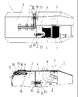
Fig. 1 shows a combat vehicle with the system according to the
}' 25 invention, much simplified; and
Fig. 2 shows a vertical section along II-II in Fig. 1.
q

212937.
Detailed Jescri~tion of the Invention
In F'i.<~s. 1 aria 2 the body 1. of an aw~momci personnel ct~rr i<.u :s
indicated in rough outlines. In its interior is a crew cabin 2
wtoich extends forwa=d to the driver :~c.ar. 3 and can be l.igtmly
sealed on top by m=a:~s of a cover 4.
Next to the driver seat 3 i.s the engine room 5 which is
completely separated rrom the crew cabin 2 and can be recognized
outside by the air supply grill 6 and the air exhaust grill 7. 2n
the interior of tre engine room is an engine 8, which is only
suggested here and may be a water-cooled engine for instance, a
connected radiator 9 and a cooling blower 10. This cooling blower
is very strong and has generous dimensions. The throttling effect
of the air supply grill 6 produces an underpressure in the engine
room 5. With an air-cooled engine an analogous blower would be
provided.
At the outer wall of body 1, an air suction hood 12 is
installed, from which the air is conveyed via a coarse filter 13,
a blower 14 and a chemical filter 15 into the air distribution
channel 16. Fresh air is then blown into the crew cabin at
approximate locations from various air blowing nozzles 17.
Between crew cabin 2 and the,engine room 5, a passage opening
20 is provided. A pine socket 21 containing a butterfly valve 22
and a sound absorber 23 are connected to the passage opening.
The ventilation system operates as follows. When the
butterfly valve 22 is open, the underpressure in the engine room 5
sucks used air frc~ the crew cabin 2. When the cover 4 is open,
5

~1~9~"~''
this sucking causes possible powder cases to be removed from the
crew cabin 2, i.i: necessary even witho~:~ :~wi.tching on tl~e I:r:~es:tr-oir
ve::tilator 14. when the cover 4 is closed, the underpressure i.n tlla
engine room S also produces a lowering of the pressure in the crew
cat:in 2, thereby assisting the ventilator 14. 'This means drat tlr.:
ventilator 14 need not cover the entire pressure drop i.n the air
filters 13, 15 and in the air distribution channel 16 with blowing
nozzles 17. !herefore, the ventilator 14 need only be designed for
a _elatively low pressure increase which makes it possible to use
an axial ventilator. Axial ventilators are characterized by low
space requirement, i.e., a short length in the flow direction, and
high air throughput but their pressure increase is limited.
The pipe socket 21 connected to the passage opening 20 also
contains a sound absorber 23 so that the noise of the engine room
cannot penetrate into the crew cabin 2. The butterfly valve 22 is
closed by the control element 29 when the engine is shut off or
when the air pressure in the engine room rises. However, the
butterfly valve 22 can also be made in the form of a non-return
valve or some other type of safety valve which closes automatically
when the pressure in the engine room rises.
While the invention has been described by reference to a
specific embodiment, this was for purposes of illustration only.
Numerous alternative embodiments will be apparent to those skilled
in the art and are considered to be within the scope of the
. 25 invention.
6

Representative Drawing
A single figure which represents the drawing illustrating the invention.
Administrative Status

2024-08-01:As part of the Next Generation Patents (NGP) transition, the Canadian Patents Database (CPD) now contains a more detailed Event History, which replicates the Event Log of our new back-office solution.

Please note that "Inactive:" events refers to events no longer in use in our new back-office solution.

For a clearer understanding of the status of the application/patent presented on this page, the site Disclaimer , as well as the definitions for Patent , Event History , Maintenance Fee  and Payment History  should be consulted.

Event History

Description Date
Time Limit for Reversal Expired 2007-08-03
Letter Sent 2006-08-03
Inactive: IPC from MCD 2006-03-11
Grant by Issuance 2004-04-20
Inactive: Cover page published 2004-04-19
Pre-grant 2004-02-09
Inactive: Final fee received 2004-02-09
Notice of Allowance is Issued 2003-11-04
Letter Sent 2003-11-04
Amendment Received - Voluntary Amendment 2003-10-23
Inactive: Received pages at allowance 2003-10-23
Inactive: Office letter 2003-10-14
Inactive: Approved for allowance (AFA) 2003-10-06
Amendment Received - Voluntary Amendment 2001-05-09
Letter Sent 2001-05-09
Inactive: Status info is complete as of Log entry date 2001-05-09
Inactive: Application prosecuted on TS as of Log entry date 2001-05-09
Request for Examination Requirements Determined Compliant 2001-04-11
All Requirements for Examination Determined Compliant 2001-04-11
Application Published (Open to Public Inspection) 1995-02-05

Abandonment History

There is no abandonment history.

Maintenance Fee

The last payment was received on 

Note : If the full payment has not been received on or before the date indicated, a further fee may be required which may be one of the following

  • the reinstatement fee;
  • the late payment fee; or
  • additional fee to reverse deemed expiry.

Please refer to the CIPO Patent Fees web page to see all current fee amounts.

Owners on Record

Note: Records showing the ownership history in alphabetical order.

Current Owners on Record
STEYR-DAIMLER-PUCH AKTIENGESELLSCHAFT
Past Owners on Record
GERHARD SKOFF
Past Owners that do not appear in the "Owners on Record" listing will appear in other documentation within the application.
Documents

To view selected files, please enter reCAPTCHA code :


To view images, click a link in the Document Description column. To download the documents, select one or more checkboxes in the first column and then click the "Download Selected in PDF format (Zip Archive)" or the "Download Selected as Single PDF" button.

List of published and non-published patent-specific documents on the CPD .

If you have any difficulty accessing content, you can call the Client Service Centre at 1-866-997-1936 or send them an e-mail at CIPO Client Service Centre.


Document
Description 
Date
(yyyy-mm-dd) 
Number of pages   Size of Image (KB) 
Representative drawing 1998-08-03 1 18
Description 1995-07-15 6 186
Claims 1995-07-15 2 30
Drawings 1995-07-15 2 35
Abstract 1995-07-15 1 12
Abstract 2003-10-23 1 15
Claims 2003-10-23 2 32
Cover Page 1995-07-15 1 128
Representative drawing 2004-03-16 1 11
Cover Page 2004-03-16 1 37
Reminder - Request for Examination 2001-04-04 1 117
Acknowledgement of Request for Examination 2001-05-09 1 178
Commissioner's Notice - Application Found Allowable 2003-11-04 1 159
Maintenance Fee Notice 2006-09-28 1 173
Correspondence 2003-10-14 1 22
Correspondence 2003-10-23 3 57
Correspondence 2004-02-09 1 33
Fees 1995-07-23 1 72