Note: Descriptions are shown in the official language in which they were submitted.
D~N, DAN & DAN
2~29~0~ :
CONDUCTIVE CONNECTOR APPARATUS .
. .
FIELD OF lr~v~iN~ oN
:
The present invention relates to a conductive connector ~;
apparatus suitable for applying when attaching an electrical :
component, such as an interior lamp, to the painted surface of a
conductive plate such as the surface o~ an automobile body, and
grounding said body.
BACKGROUND OF THE INv~ lON
Thi~s type of prior art involves performing body grounding by
opening a~hole in the pa1nted~surfaoe~of a conductive attaching
body such ss an automobile body and fa~steniny toyether a lead
s~wire and bus ~ar wlth screws,
An example of this type of prior art is described i n
Japanese Patent Utillty Model Publication No. 4-49461.
In this exam~le of the prior art, to~ether with arranging a
conductive member, having a bent piece inserted into a hole
: formed adjacent to an attachment hole of an insulated attached
body, on the surface of said attached body, the surfaoe of said
:attached body on whlch a conductive member is arranyed makes :~ .
'
DAN, DAN & DAN 212960~
planar contact with a conductive attaching body so that by
tightly fastening said attached body to hole 8 of this conductive
attaching body with a conductive screw inserted through said
attachment hole, the end o~ the bent piece of said conductive
member is connected to the inner surface of the hole of said
conductive attaching body with said conductive screw while
scratching off on the inner surface of the screw head.
In this example o~ the prior art, in the attaching of an
interior lamp and so forth by fastening with screws to the
automobile body, since there are no reinforcing members,
particularly on the inner surface and periphery of the
cylindrical attachment hole of a plastic attached body, the
problem is encountered wherein a completely satisfactory
attachment state cannot always be obtained due to the cracking,
cutting, tearing or breaking oif of the attached body due to the
powerful twisting force of tha set screws.
In addition, there is also tha pxoblem o~ the conductive
member, integrated into a single unit with a bus bar, becoming
dlsplaced by the turning force of the screws.
.: .; .
In addition, since the attached body is attached by only its
surface on which a conductiva member is arrangad making planar
contact with an attaching body, there was also the problem of it
~ being subjected to restrictions on its direction of attachment.
s~ ~ Namely, since handling of lead wires and bus bars is ~ ~
: ,
' .,
2 ;
.
DAN, DAN & DAN
212960~
troublesome at visible locations such as door switches and
interior electrical components such as interior lamps, not to
mention locations hidden from sight, and the screws would become
loose due to vibrations and so forth, numerous problems arose
such as requiring the use of spring washers.
Consequently, although there are other examples of the prior
art which prevent partial damaye to the attached body by the
above-mentioned fastening by screws by embedding a reinforcing
ring by insertion molding in line with the attachment hole, even
in the case of such examples of the prior art, there is the
problem of molding costs becominy expensive due to the need for
means of ~lastic insert molding.
~: Therefore, although it is possihl~ to consider simply
:
~: tightly fitting or loosely fittiny a reinforcing ring in the
above-mentioned cylindrical attachment hole~ in the case this is ~
~:~ tightly fit, a press machine is re~uirecl while also resultin~ in .
poor workability~ In contrast, in the case said reinforcin~ ring
is loosely fit, there are problems such as the ring easily
:
falling out to the outside or still requiring the use of a spriny
I washer.
~ ' .
SUMMARY OF THE INVENTION
In order ~o eliminate each of the above-mentioned problems,
~ , -~; : ;. : . ~ :
.. :~ . , " : . . :. .
.: ~ . : . , .:
; i : . . ...
, ................................................ ..
DAN, DAN & DAN 212 9 6 0 j
the present invention improves the shape of the attachment hole
of the attached body by inserting a cylindrical bent ~iece, of
which at least one side extending from a conductive member is
formed into a flat surface, along the inner sur~ace of the
attachment hole itself of an attached body, followed by fastening
the attached body to a conductive attaching body with a
conductive screw.
Accordingly, the ob~ect of the present invention is to
reinforce the periphery of the above-mentioned attachment hole
with the bent piece, and lock the conductive member in positio~
without beiny displaced, thus accommodating the direction of
attachment of the attached body and preventing loosening of the
conductive screw by the resilient force of bending following
: fastening of the bent piece with the screw, and therehy
eliminating the need for a spring washer.
In the composing of an apparatus whlch attaches a conductive
~: member, arranged on the surface of an insulated attached body, to
a conductive attaching member, the above-mentioned object of the
present invention is accomplished by arranging a conductive
I i memberj having a bent piece aligned with the inner sur$ace of an
attachment hole o$ an insulated attached body made of ulastic and
so forth, slightly protruding from said inner surface and
inserted into this attachment hole, on the surface of said
attached body, and said attached body making planar contact with
: . 4
.:J, :':' ' ' . ,' ' . . , "" : '
~fff',
.DAN, DAN & DAN 212 9 6 0 ~
a conductive attaching body so that by tightly fastening said
attached body to the hole of this conductive attaching body with
a conductive screw inserted through the hent piece within said
attachment hole, the bent piece of said conductive member is
forcibly bent, and its end is connected to the inner surface of
the hole of said conductive attaching body with said conductive
screw while maintaining electrical continuity.
::~ When the attached body is fastened in the hole of a
conductive attaching body with a conductive screw inserted into
the attachment hole of said attached body, since a conductive
'
bent piece is present within the attachment hole of said attached
body aligned al~ng its inner surface, the inner surface and
: periphery of said attachment hole can be reinforced, thus
enabllng said attached body to be securely fastened to the
ainted surface of a conductive attaching body without~being cut,
torn or broken off by the twisting force of the conduotive screw.
Moreover, during this fastening, since the bent piece of the
:: ~
conductive member is pushed against the painted surface of the
conductive attaching body by the twisting force of the conductive
screw,lwhile the conductive screw is screwed into the hole of the
conductive attaching body while forcibly pushlng the projecting
portion of the bent piece into an attachment ho.le with the inner
surface of thje head of the conductive screw, the conductive screw
can be screwed in at a right angle to the conductive attaching
s,
, .
. DAN, DAN & DAN 212 9 6 0 ~
body.
In addition, by tightly fastening the attached body in the
hole of the conductive attaching body with a conductive screw ;~
inserted throuyh an attachment hole of said attached body, the . :
projecting portion of the bent piece of said conductive member is ; .
forcibly pushed into the attachment hole by the powerful twisting ~ ~:
force of said conductive screw, thus enabliny the bent piece to :
make resilient contact with the inner surface of the head of the : ;
conductive screw by strongly bendiny the bent piece with slight ~ ;
looseness. Together with said conductive member being able to be ~ .
connected to the inner surface of the hole of the conductive ~-
attaching body whil~e maintaining electrical continuity, the :~
conductive screw following thls fastening is not inadvertently '~
loosened by external disturbances such as vibrations and so forth :::
,~ ;
due~to the powerful resillent contact friction of~said bent piece ;~
maklng secure resilient contact with the inner surface of its
head portion. .;
According to another embodiment of the present invention,
whiIe the bent piece of a conductive member is pushed against the
,: ~
painted surface of a conductive attaching body by the twisting ~ :~
force of a conductive screw during fastening, since the
conductive screw is screwed into an attachment hole while a ~
projection provided on the bent piece forcibly scratches and cuts ~ ;
into the inner surface of the head portion of the conductive
': ':
'.
,~", " ,f,,,, , ,,,",,~",,;,,, ,,," " j ,, ~ f{ ;", '~ ~, "' ,, " , .i,
DAN, DAN & DAN 212 9 6 0 ~
screw, the conductive screw is screwed in at a right angle to the
conductive attachlng body.
Namely, as a result of the above-mentioned bent piece being
tightly clamped by a projecting residual portion between the
inside of the head of the conductive screw and the painted
surface of the conductive attachiny body in the state wherein the
majority of its projection has been scratched and cut away, the
above-mentioned conductive member can be favorably connected to
the conductive attaching body at the innar surface of its hole
through the conductive scxew by means of its bent piece while
maintaining electrical continuityO
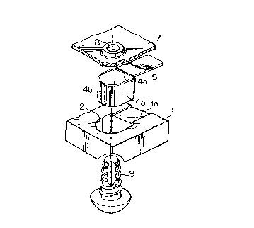
BRIEF DESCRIPTION OF THE DRAWINGS
Fig. 1 is a cross-sectional view indicating an embodiment of
the present invention.
Fig. 2 is an exploded perspective view indicating an
~ ~ :
embodiment of the present invention.
Figs. 3A and 3B are cross-sectional views during the course
o~ assembly of an embodiment of the present invention.
Fig. 4 is a cross-sectional view during the course of
assembly o~ an embodiment of the present invention.
~ ~ Fi~s. 5A and 5B are perspective views indicating other
:
. :
DAN, DAN ~ DAN 2129 6 0 a
examples of bent pieces oE the conducting member.
Figs. 6A and 6B are perspective views indicating another
example of bent ~ieces o~ the conducting member.
Figs. 7A and 7B are perspectiye views indicating other
examples of bent pieces of the conducting member.
Fig. 8 is a cross-sectional view indicating another example
of the present invention.
Fig. 9 is a cross-sectional view indicating another example
of the present invention.
,
~ DETAILED DESCRIPTION OF THE
.. . ~ .
;~ PREFERRED EXEMPLARY EMBODIMENTS
: .: .:
The following provides an explanation of a first embodiment
of the present invention with reference to the drawings.
First, with respect to the basic constitution of the present
invention, in the attaching of a conductive member arranged on
the surface of an insulated attached body to a conductive
attaching body while maintaining electrical continuity, a
conductive member 5, in the form of a bus bar and so forth,
having bent pieces 4a and 4b inserted as shown in Fig. 3A in
attachment hole 2 of an insulated attached body 1 made of plastic
:.
DAN, DAN ~ DAN 212 9 6 0 ~
and so forth as shown in Fig. 2 and slightly projecting from said
attachment hole 2 aligned along its inner surface, is arranged on
the surface of the above-mentioned attached body 1, for example
on flat groove 1a.
As a result of the surface of the above-mentioned attached
body 1 on which the conductive member is arranged making planar
contact with metal conductive attaching body 7 as shown in Fig.
4, and tightly fastening the above-mentioned attached body 1 to
hole 8 of conductive attaching body 7 as shown in the same
drawing, or to a nut welded to conductive attaching body 7 in
place of this hole 8, with conductiv~ screw 9, in the form of a
tapping screw and so forth, inserted through the above-mentioned
attachment h~le 2, leading projection 3 of bent piece 4 of the
above-mentioned conductive member 5 is forcibly pushed into
.~ .
attachment hole 2 by the powerful twisting force of the above-
mentioned conduotive screw 9, thus enabling bent pieae 4b to be
strongly bent with slight looseness and make resilient contact
;~ with the inner surface of the head of conductive screw 9 as shown
in Fig. 1, resulting in the above-mentioned conductive member 5
beingiable to be connected to the inner surface of hole 8 of
conductive attaching body 7 while maintaining electrical
continuity.
The followiny provides an explanation of the operation of
the present invention.
: . ' 9 .:
,, ,, , ,
,.,,,, : .
. DAN, DAN ~ DAN
-- 2 1 2 9 6 ~
As a result of paint being peeled from the inner surface of
hole 8 formed in conductive attaching body 7 during drilling or
burring, the inner surface of the above-mentioned hole 8 or a nut
welded to conductive attaching body 7 is electrically conductive~
In addition, when attached body 1 is fastened to hole 8 of
conductive attaching body 7 with conductive screw 9 inserted
throug~ bent pieces 4a and 4b as shown in Fig. 3A inside
attachment hole 2 of attached body 1, since conductive bent
pieces 4a and 4b are present inside attaohment hole 2 of attached
body 1 and are aligned with its inner surface, the inner surface
and periphery of attachment hole 2 can be reinforced by bent
pieces 4a and 4b, thus enabling attached body 1 to be securely
ast~ned to painted surface 7a of conductive attaching body 7 as
shown ~in Fig. 1 without being cut or damaged by the twisting
force of conducti:ve screw 9, and without displaclng the bus bar
since:one side of bent piece 4a is in the form of a flat surface.
During this fastening, while bent pieces 4a and 4b of
.
conductive member S are pushed against the painted surface of
conductive attaching body 7 by the twisting force of conductive
screwl9, since conductive screw 9 is screwed into hole 8 of
- conductive attaching body 7 while projection 3 of bent pieces 4a
:: :
and 4b is forcibly pushed into attachment hole 2 by the inner ~ .
~ surface of the head of conductive screw 9, conductive screw 9 is
.~ ; screwed in and fastened at a right angle to conductive attaching . .
DAN, DAN & DAN
---' 212960~
body 7 as shown in Fi g. 1 .
Following this fastening, conductive screw 9 does not become
inadvertently loosened by external disturbances such as
vibrations and so forth due to the power~ul resilient contact
friction of the above-mentioned bent piece 4b securely making
resilient contact with the inner surface of its head.
Furthermore, the shape of bent pieces 4a and 4b to be formed
on conductive member 5 is not limited to the above-mentioned
curved cylinder, but rather various shapes of bent pieces 4a and
4b can be employed as shown in each of the drawings of Figs. 5A,
: ~,
6A and 7A.
In addition, although an example of attaching attached body
s described in the above-mentioned embodiment wherein its
surface~on which conductive member is provided makes contact with
conductive attaching body 7,~ as shown in Figs. 8 and 9, said
att~ched~body~l~may also be ~astened~with conductive screw~9 by
having the surface of said attached body 1 on which a conductive
member i~9 not arranged make contact with conductive attaching
body 7.
The following provides an explanation of a second embodiment
of the present invention with reference to the drawings.
: ~ :
First, with respect to the basic constitution of this second
embodiment, in the attaching of a conductive member arranged on
1 1 ' '
~,~,,. . ,,, , , . :
, ,',',',,.'; ., ' ; , ' ' ', : . ' ' '
, ~; ;~' : , . . .
. DAN, DAN ~ DAN
212960~
.
the surface of an insulated attached body to a conductive
attaching body while maintaining electrical continuity, bent
pieces 4a and ~b, having projection 3 which slicJhtly protrudes
from attachment hole 2 of insulated attached body 1 made of
plastic and so forth as shown in Fig. 3B, are inserted into
attachment hole 2, and conductive member 5, in the form of a
brass bus bar and so forth, which is integrated into a single
unit with bent pieces 4a and 4b, is arranged on the su~rface of
the above-mentioned attached body 1, for example on ~lat groove
1a.
: As a result of the surface of the above-mentioned attached
~: body 1 on which the conductive member is arranged making planar
contact with metal conductive attaching body 7, in the form of an
~; automobile door or chassis, as shown in Fig. 4, and tightly
fastening the above-mentioned attached body 1 to hole 8 of this
conductive attaching body 7 as shown in the same drawing, or to a
nut welded to conductive attaching body 7, with conductive screw
9; in the form of a tapping screw and so forth, inserted through
the above-mentioned attachment hole 2, the leading ends of bent
pieces~ 4a and ~b of the above-mentioned conductive member 5 can
be connected to the inner surface o~ hole 8 of the above-
: mentioned conductive attaching body 7 with the above-mentioned
screw 9 while maintaining electrical continuity.
; During thi~ fastening, while bent pieces 4a and 4b of
~':
12
. DAN, DAN ~ DAN
2129~0~
conductive member 5 is pushed a~ainst the painted surface of
conductive attaching body 7 by the twisting force of conductive
screw 9, since conductive screw 9 is screwed into attachment hole
2 while pro~ection 3 of bent pieces 4a and 4b is forcibly
scratched and cut by the inner surface of the head of conductive
screw 9, conductive screw 9 is screwed in and fastened at a right
angle to conductive attaching body 7.
Namely, as a result of the above-mentioned bent pieces 4a
and 4b being tightly clamped by means of projection residual
portion 3a between the inside of the head of conductive screw 9
and the painted surface of conductive attaching body 7 in the
state wherein the majority of its projection 3 has been scratched
and cut away, the above-mentioned conductive member 5 can be
favorably connected to conductive attaching body 7 at the inner
~ ~:
sur~ace of its hole 8 through conductive screw 9 by means of its :-
bent pieces 4a and 4b while maintaining electrical:continuity.
In addition, following this fastening, conductive screw 9 :~
does not become inadvertently loosened by external disturbances ~ :
such as vibrations and so forth due to the powerful resilient ~ :
: :
i contact friction resulting from the small residual portion 3a of
projection 3 of the above-mentioned bent pieces 4a and 4b
securely inserted and making contact with the inner surface of
its head.
~: ~: . .
~;Furthermore, the shape of bent pieces 4a and 4b to be formed : :
. . '.
," 1,,:,,,,, . . " , . . : , .. .. ,;.. " , ,.
' DAN, DAN ~ DAN :-
212960~ ::
.. :
on conductive member 5 is not limited to the above-mentioned ~:
curved cylinder, but rather various shapes of bent pieces 4a and
4b can be employed as shown in each of the drawings of Figs. 5B,
6B and 7. .
As a result of having the composition as explained above,
the present invention offers the advantages described below.
When fastening attached body 1 to hole 8 of conductive
attaching body 7 with conductive screw 9 inserted into attachment
hole 2 of attached body 1, since conductive bent pieces 4a and 4b
are present in attachment hole 2 of attached body 1 aligned with
its inner surface, the inner surface and periphery of attachment - .
hole 2 are able to be reinforced by bent pieces 4a and 4b, thus
offering the advantage in terms of manufacturing since attached
body:1 can be seourely fastened to painted surface 7a of
conductive attaching body 7 without being cut or broken off by
the twisting force of conductive screw 9. . :
During this fastening, while bent pieces 4a and 4b of ~ : .
conductive member 5 are being pushed against painted surface 7a
of conductive attaching body 7 by the twlsting force of . .
conductive screw 9, since conductive screw 9 is screwed into hole
8 of conductive attachlng body 7 while projection 3 of bent
. :, .
ieces 4a and 4b i5 forcibly pushed into attachment hole 2 by the
~:~: inner surface of the head of conductive screw 9, conductive screw
:: , .
- '
, . . ..
.:: . 14
1, 1 ~
DAN, DAN & DAN
212960a
9 is able to be screwed in and fastened at a riyht anyle to
conductive attaching body 7, and is not ina~vertently loo~ened by
external disturbance in the ~orm of vibrations and so on due to
the powerful resilient contact friction of the above~mentioned
bent piece 4b securely makiny resilient contact with the inner
surface of its head, thereby of~ering the advantage of
eliminating the need for a spring washer.
In addition, since projection 3 of bent pieces 4a and 4b of
the above-mentioned conductive member S is forcibly pushed into
attachment hole 2 by conductive screw 9 inserted in hole 8 of
conductlve attachins body 7 through attachment hole 2 of the
above-mentioned attached body 1 due to the powerful twisting
~ - .
force of the above-mentioned conductive screw 9 as shown in Fig.
; 1, enabling it to make resilient contact with the inner surface
of the head of conductive~screw 9 as shown in Fig. 1 as a result
of stronyly bending bent piece 4b with sliyht looseness, the
above-mentioned conductlng member 5 is able to be connected to
the inner surface of hole 8 of conduative attaching body 7 while
maintaininy electrical continuity, thereby offering numerous
advantiayes ~ncluding being able to reliably maintain a state of
electrical continuity for a lony time.
, ~ ,
", ",,."; ,, " ,,, , " , . .,, , , , :,, " ., . , : ,