Language selection

Search

Patent 2129814 Summary

Third-party information liability

Some of the information on this Web page has been provided by external sources. The Government of Canada is not responsible for the accuracy, reliability or currency of the information supplied by external sources. Users wishing to rely upon this information should consult directly with the source of the information. Content provided by external sources is not subject to official languages, privacy and accessibility requirements.

Claims and Abstract availability

Any discrepancies in the text and image of the Claims and Abstract are due to differing posting times. Text of the Claims and Abstract are posted:

  • At the time the application is open to public inspection;
  • At the time of issue of the patent (grant).
(12) Patent: (11) CA 2129814
(54) English Title: ROOF VENT RAIN DEFLECTOR
(54) French Title: SYSTEME D'AERATION A L'EPREUVE DE LA PLUIE
Status: Term Expired - Post Grant Beyond Limit
Bibliographic Data
(51) International Patent Classification (IPC):
  • F24F 07/02 (2006.01)
  • B60H 01/26 (2006.01)
  • F24F 13/10 (2006.01)
(72) Inventors :
  • PINDER, ROBERT CLAYTON (Canada)
(73) Owners :
  • MILDRED GRACE PINDER
  • ELIZABETH CHERYL ZVANIGA
  • BRYAN NORMAN PINDER
(71) Applicants :
  • MILDRED GRACE PINDER (Canada)
  • ELIZABETH CHERYL ZVANIGA (Canada)
  • BRYAN NORMAN PINDER (Canada)
(74) Agent: AVENTUM IP LAW LLP
(74) Associate agent:
(45) Issued: 1997-03-04
(22) Filed Date: 1994-08-09
(41) Open to Public Inspection: 1996-02-10
Examination requested: 1994-08-09
Availability of licence: N/A
Dedicated to the Public: N/A
(25) Language of filing: English

Patent Cooperation Treaty (PCT): No

(30) Application Priority Data: None

Abstracts

English Abstract

A rain deflector for a vehicle roof vent consists of a pair of like panels one of which is fastened to the cap of the roof vent and moves therewith, and is hinged to the second panel which has the end remote from the hinge connected to slide along tracks on the vehicle roof. Each panel is substantially larger than the vent cap, to extend beyond the edges of the vent and prevents rain from entering the vent while permitting ventilationof air through the vent.


French Abstract

Un déflecteur de pluie pour un évent de toit de véhicule se compose d'une paire de panneaux identiques dont un est fixé sur le capuchon de l'évent de toit et se déplace avec celui-ci, et est articulé au deuxième panneau dont l'extrémité éloignée de la charnière est connectée de manière à glisser le long de rails sur le toit du véhicule. Chaque panneau est nettement plus grand que le bouchon d'évent, de manière à s'étendre au-delà des bords de l'évent et à empêcher la pluie de pénétrer dans l'évent tout en permettant la ventilation par l'évent.

Claims

Note: Claims are shown in the official language in which they were submitted.

- 6 -
CLAIMS
1. A roof vent rain deflector adapted to cooperate with a standard
hinged cap roof to prevent rain from entering the vent when said
cap is raised, said deflector comprising;
a first panel adapted to be attached to and overlie said cap
and extend beyond the edges of said cap for a distance
approximately half the width of said cap,
a second panel of substantially the same size as said first
panel hinged to said first panel at the end of said first panel
remote from the hinged end of said roof cap,
track means adapted to be fastened to the roof of a vehicle
equipped with said roof vent, and positioned to provide a sliding
connection to the unhinged end of said second panel,
and means connecting said second panel in sliding relation to
said track means , whereby when said cap is opened, said first
panel is moved with said cap, and the edge of said second panel
which is hinged to said first panel moves upwardly towards said
roof cap, and the unhinged edge of said second panel moves along
said track means, said two panels forming a pair of triangular
openings permitting flow of air from said vent while preventing
rain from entering therein.
2. A rain deflector as claimed in claim 1, wherein said first and
second panels and said hinge are formed froma single sheet of
thermoplastic material
3. A rain deflector as claimed in claim 1, wherein said tracks
are formed of metal, and are provided with a longitudinally
extending slot in each track, and a sliding axle assembly is

- 7 -
connected to each side of said second panel and slides in said slot
in said track.
4. A rain deflector as claimed in claim 1,2,or 3 including splash
matting adapted to be positioned adjacent said roof vent to
prevent rain from bouncing on said roof and into said vent.

Description

Note: Descriptions are shown in the official language in which they were submitted.


ROOF VENT RAIN DFFLFCTOR 2 ~. 2 9 ~14
FIFLD OF ~ NVh..llON
The present invention relates to a device which, when
installed over a standard vehicle ventilating hatch, allows a full
flow of warm air out of the vehicle through the hatch, and also
keeps rain from entering the vehicle through the hatch.
The standard roof vent used by most recreation vehicles
in North America has a fourteen inch square opening through the
roof, over which an adjustable hatch vent unit is installed. This
unit has a crank-up mechanism attached to a hinged cap, which when
closed, keeps out the rain, but when raised to full height rotates
upward at approximately a fifty to sixty degree angle to the
horizontal, allowing full ventilation. Unfortunately, when open,
the vent cannot prevent rain from entering the vehicle that it is
installed upon.
BAC~OUND OF 1~ lNv~ ON
There are known units for moving vehicles, buses and cars
using openings in the roof and covered by a fixed lid mounted over
openings which vent out the back of the lid. Another type is a
dome mounted permanently over the roof vent with a small screened
and louvered area on one vertical side. Reference is made to
United States Patents 4,592,269 dated June 30, 1986 to Lamparter
and 1,539,534 dated May 1925 to Ansell, which show examples of such
prior art devices. Although these units keep rain out of a
vehicle, the volume of air exhausted is very small when the vehicle
~r

2.t..29~i~
is stationary. These units need forward motion to provide adequate
ventilation.
There has been a need for rain protection plus full
ventilation for as long as these types of roof vents have been
used. Also, a survey of registered recreation vehicles shows over
twenty-six million units in North America. Accordingly, there is
a well defined demand for the device of the present invention.
BRI8F D8SCRIPTION OF 1~ DRAWINGS:
In the accompanying drawings,
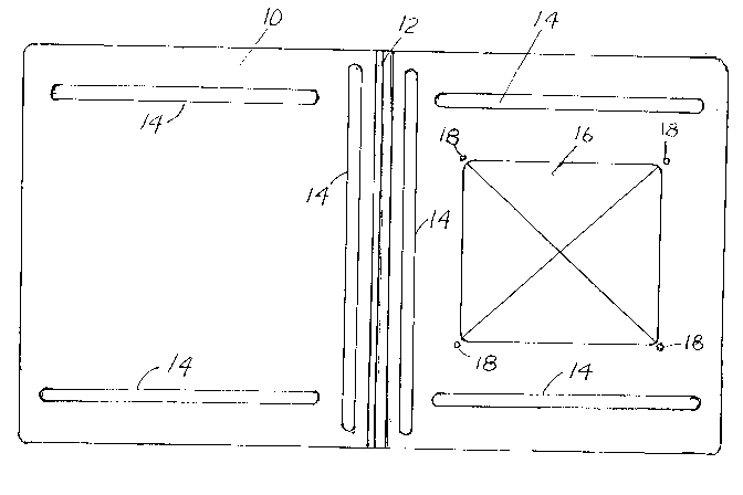
Figure 1 is a top view of the roof vent rain deflector of the
invent ion;
Figure 2 is an end view of the deflector shown in Figure 1 showing
two support legs which are used to support the sliding end section
of the deflector;
Figure 3 is a side view of the deflector shown in Figure 1 showing
a rear support leg, hinged centre area and a domed section shaped
to fit over and embrace a vent roof cap.
Figure 4 is a side view of the slide track showing the slotted area
and mounting fasteners to mount the deflector to the roof of a
vehicle;
Figure 5 is an exploded view of a support leg, the end of a slide
track and sliding axle assembly;
Figure 6 is a top view of the slide track of Figure 5 with the
sliding axle assembly engaged in the track;
Figure 7 is a side view of the deflector of Figure 1 installed on
a vehicle roof;

2~ 29~3i4
Figure 8 is a top view of the device installed on a roof vent
hatch, in the closed position, and
Figure 9 is a side view of a the well known roof vent used on most
recreation vehicles partially open, and showing how easily rain may
enter the vent. This illustrates type of unit that the deflector
is intended to protect.
D~TAIL~D D~SCRIPTION OF 1~ INVENTION
Referring to Figure 1 there is shown a plastic one-piece
lid 10, having a flexible integral hinge 12, and reinforcing ribs
14. One end of the lid 10 has a domed section 16 and is provided
with four mounting holes 18 for attachment to the cap of a roof
vent.
Figure 2 is an end elevation of the lid 10 of Figure 1
showing support legs 20 extending below the lid 10. In Figure 3
the lid 10 is shown in side view, clearly showing the relationship
of the the domed section 16, the flexible hinge 12 and the support
legs 20.
Figures 4, 5, and 6 illustrate a slide track 22, fasteners 24 used
to mount the slide track 22 to the roof of the vehicle, and the
sliding axle assembly 26 used to connect the support legs 20
(Figure 2) to the the slide tracks 22 of the device. The sliding
axle assembly 26 consists of a bolt 38, a sleeve 40, nuts 42 and
washers 44 It will be appreciated by those skilled in the art
that two slide tracks 22 and two sliding axle assemblies 26 are
required for each lid 10, the tracks 22 being mirror images of

2~ 29~i4
each other and mounted on the vehicle roof on opposite sides of the
roof vent frame, as explained hereinafter.
Figure 7, which is a side view of the deflector mounted
on the roof of a vehicle 36, with the roof vent hatch assembly in
a partly open position, illustrates the operation of the deflector
of the present invention. In the open position, the lid 10 is
urged upward by the roof vent cap 34 and folds along flexible hinge
12 with domed section 16 nesting with the vent cap 34. Sliding
axle assemblies 26 slide along slide tracks 22, permitting full
flow of exhaust air through the vent opening, while covering the
vent opening to prevent rain from entering the vent. Vent frame 30
defines the area of the opening over which the cap spans when the
vent is in the closed position. Arm 32 is a component of the roof
vent mechanism, which controls the position of the cap 34, and does
not form part of the device of the present invention. A splash
arresting mat 28 is positioned on either side of the roof vent
frame 30 to prevent splashing of rain drops from the roof into the
vent opening. As shown, tracks 22 are mounted parallel to the
sides of the roof vent frame, but displaced to the end of the frame
which would be the down wind end when the vehicle is in motion.
Figure 8 is a plan view of the deflector of the present invention
in closed position, and mounted on the roof of a vehicle over the
roof vent. The tracks 22 are fastened directly to the vehicle roof
36 with the sliding axle assemblies 26 engaged in the slots of the
tracks 22 and with the domed section 16 of the deflector secured to
the vent cap by fastenings (not shown) passing through mounting

2l2~14
holes 18 and connected to the vent cap. The splash arresting mat
sections 28 are partially visible extending beyond the edges of the
deflector.
Figure 9 illustrates the prior art situation where no
protection is provided to prevent rain from enteringthe roof vent,
highlighting the risk of such a vent admitting rain.
Thus the rain deflector of the present invention serves
to keep rain from entering an open roof vent while permitting full
ventilation through the vent.

Representative Drawing
A single figure which represents the drawing illustrating the invention.
Administrative Status

2024-08-01:As part of the Next Generation Patents (NGP) transition, the Canadian Patents Database (CPD) now contains a more detailed Event History, which replicates the Event Log of our new back-office solution.

Please note that "Inactive:" events refers to events no longer in use in our new back-office solution.

For a clearer understanding of the status of the application/patent presented on this page, the site Disclaimer , as well as the definitions for Patent , Event History , Maintenance Fee  and Payment History  should be consulted.

Event History

Description Date
Inactive: Adhoc Request Documented 2018-06-06
Revocation of Agent Requirements Determined Compliant 2018-05-18
Appointment of Agent Requirements Determined Compliant 2018-05-18
Inactive: Expired (new Act pat) 2014-08-09
Letter Sent 2010-05-11
Inactive: Single transfer 2010-04-23
Letter Sent 2008-08-14
Inactive: Single transfer 2008-08-05
Inactive: Agents merged 2003-12-09
Grant by Issuance 1997-03-04
Small Entity Declaration Determined Compliant 1996-03-19
Application Published (Open to Public Inspection) 1996-02-10
All Requirements for Examination Determined Compliant 1994-08-09
Request for Examination Requirements Determined Compliant 1994-08-09

Abandonment History

There is no abandonment history.

Fee History

Fee Type Anniversary Year Due Date Paid Date
MF (patent, 4th anniv.) - small 1998-08-10 1998-08-07
MF (patent, 5th anniv.) - small 1999-08-09 1999-08-06
MF (patent, 6th anniv.) - small 2000-08-09 2000-07-18
MF (patent, 7th anniv.) - small 2001-08-09 2001-08-01
MF (patent, 8th anniv.) - small 2002-08-09 2002-08-07
MF (patent, 9th anniv.) - small 2003-08-11 2003-07-25
MF (patent, 10th anniv.) - small 2004-08-09 2004-07-27
MF (patent, 11th anniv.) - small 2005-08-09 2005-07-25
MF (patent, 12th anniv.) - small 2006-08-09 2006-07-12
MF (patent, 13th anniv.) - small 2007-08-09 2007-06-22
MF (patent, 14th anniv.) - small 2008-08-11 2008-06-19
Registration of a document 2008-08-05
MF (patent, 15th anniv.) - small 2009-08-10 2009-07-29
Registration of a document 2010-04-23
MF (patent, 16th anniv.) - small 2010-08-09 2010-06-30
MF (patent, 17th anniv.) - small 2011-08-09 2011-08-05
MF (patent, 18th anniv.) - small 2012-08-09 2012-08-08
MF (patent, 19th anniv.) - small 2013-08-09 2013-08-07
Owners on Record

Note: Records showing the ownership history in alphabetical order.

Current Owners on Record
MILDRED GRACE PINDER
ELIZABETH CHERYL ZVANIGA
BRYAN NORMAN PINDER
Past Owners on Record
ROBERT CLAYTON PINDER
Past Owners that do not appear in the "Owners on Record" listing will appear in other documentation within the application.
Documents

To view selected files, please enter reCAPTCHA code :


To view images, click a link in the Document Description column. To download the documents, select one or more checkboxes in the first column and then click the "Download Selected in PDF format (Zip Archive)" or the "Download Selected as Single PDF" button.

List of published and non-published patent-specific documents on the CPD .

If you have any difficulty accessing content, you can call the Client Service Centre at 1-866-997-1936 or send them an e-mail at CIPO Client Service Centre.


Document
Description 
Date
(yyyy-mm-dd) 
Number of pages   Size of Image (KB) 
Description 1996-02-09 2 68
Abstract 1996-02-09 1 42
Claims 1996-02-09 1 30
Drawings 1996-02-09 4 55
Drawings 1996-04-06 4 55
Claims 1996-04-06 1 30
Abstract 1996-04-06 1 42
Description 1996-04-06 2 68
Abstract 1997-02-24 1 15
Description 1997-02-24 5 169
Drawings 1997-02-24 5 89
Claims 1997-02-24 2 49
Representative drawing 1999-06-21 1 15
Courtesy - Certificate of registration (related document(s)) 2008-08-13 1 104
Courtesy - Certificate of registration (related document(s)) 2010-05-10 1 101
Fees 1998-08-06 2 65
Fees 2001-07-31 1 35
Fees 2000-07-17 1 30
Fees 1999-08-05 1 36
Fees 2011-08-04 1 200
Fees 1996-08-11 2 72
Fees 1995-08-30 2 72
Prosecution correspondence 1996-03-18 2 48
PCT Correspondence 1996-11-27 1 30
PCT Correspondence 1996-12-12 1 32
PCT Correspondence 1996-12-16 1 92
Examiner Requisition 1995-09-18 2 90
Courtesy - Office Letter 1997-01-20 1 16
Courtesy - Office Letter 1996-05-05 1 20