Language selection

Search

Patent 2130057 Summary

Third-party information liability

Some of the information on this Web page has been provided by external sources. The Government of Canada is not responsible for the accuracy, reliability or currency of the information supplied by external sources. Users wishing to rely upon this information should consult directly with the source of the information. Content provided by external sources is not subject to official languages, privacy and accessibility requirements.

Claims and Abstract availability

Any discrepancies in the text and image of the Claims and Abstract are due to differing posting times. Text of the Claims and Abstract are posted:

  • At the time the application is open to public inspection;
  • At the time of issue of the patent (grant).
(12) Patent: (11) CA 2130057
(54) English Title: DIAGONALLY BRACED RAIL TRUCK WITH IMPROVED END BLOCK
(54) French Title: BOGIE CONTREVENTE, AVEC CALES D'EXTREMITE AMELIOREES
Status: Term Expired - Post Grant Beyond Limit
Bibliographic Data
(51) International Patent Classification (IPC):
  • B61F 5/50 (2006.01)
  • B61F 5/52 (2006.01)
(72) Inventors :
  • SARNICKI, JOHN T. (United States of America)
  • BERG, THOMAS R. (United States of America)
(73) Owners :
  • STANDARD CAR TRUCK COMPANY
(71) Applicants :
(74) Agent: DENNISON ASSOCIATES
(74) Associate agent:
(45) Issued: 1998-08-25
(22) Filed Date: 1994-08-12
(41) Open to Public Inspection: 1996-01-06
Examination requested: 1995-09-01
Availability of licence: N/A
Dedicated to the Public: N/A
(25) Language of filing: English

Patent Cooperation Treaty (PCT): No

(30) Application Priority Data:
Application No. Country/Territory Date
08/270,505 (United States of America) 1994-07-05

Abstracts

English Abstract


A railroad car truck includes a pair of side frames and
a bolster which is supported by springs on the side frame. There
are diagonal cross braces attached to the side frames with each
cross brace being attached to one side frame on one side of the
bolster and being attached to the other side frame on the
opposite side of the bolster. There are mounting brackets fixed
to the side frame and there is an end block attached with
elastomeric mounting elements to each mounting bracket. The end
blocks mount the cross braces. Each end block has a profile such
as not to materially interfere with the scan area of a hot box
detector mounted adjacent one of the railroad track rails.


French Abstract

Wagon de chemin de fer comportant un paire de longerons de châssis et une traverse pivot supportée par des ressorts arrimés aux logerons. Des traverses entrecroisées sont fixées aux longerons, chacune d'elles étant fixée à l'un et l'autre longerons, de part et d'autre de la traverse pivot. Des supports de montage sont fixés aux longerons avec une entretoise d'extrémité retenue par des éléments de fixation en élastomère à chaque support de montage. Les entretoises d'extrémité servent au montage des traverses entrecroisées. Chaque entretoise d'extrémité possède un profil destiné à ne pas interférer avec le bon fonctionnement détecteur de boîtes chaudes montée à proximité d'un rail du chemin de fer.

Claims

Note: Claims are shown in the official language in which they were submitted.

-1-
THE EMBODIMENTS OF THE INVENTION IN WHICH AN EXCLUSIVE
PROPERTY OR PRIVILEGE IS CLAIMED ARE DEFINED AS FOLLOWS:
1. A railroad car truck including a pair of side
frames, a bolster supported by springs on said side frames,
diagonal cross braces attached to said side frames, with
each cross brace being attached to one side frame on one
side of said bolster and being attached to the other side
frame on the opposite side of the bolster, means for
attaching each brace to a side frame including a mounting
bracket fixed to the side frame, an end block attached to
each mounting bracket, elastomeric mounting elements
interconnected between each end block and its associated
mounting bracket, each end block having a generally
circular flange adjacent an elastomeric mounting element
and an extended nose, said nose having a first portion of a
first diameter and a second end portion of a second
diameter, said second portion having a smaller diameter
than said first portion, said second portion extending
within an end of a cross brace, each end block having a
profile such as not to materially interfere with a scan
area of a hot box detector mounted adjacent one of a
railroad track rail.
2. The truck of Claim 1, characterized in that there
is a first elastomeric mounting element positioned between
said end block circular flange and one side of said
mounting bracket, and a second elastomeric mounting element
positioned on an opposite side of said mounting bracket.
3. The truck of Claim 2, characterized by and
including a locking plate positioned adjacent said second
elastomeric mounting element.
4. The truck of Claim 3, characterized in that said
locking plate, elastomeric elements and end block are all
connected together by a mounting bolt which extends from

-2-
one side of said locking plate, through said elastomeric
mounting elements and mounting bracket into said end block.
5. The truck of Claim 2, characterized by and
including holding rings positioned between each elastomeric
mounting element and said mounting bracket.
6. The truck of Claim 1, characterized by a plurality
of fillets extending between each end block circular
flanges and its nose.
7. An end block for use in attaching a cross brace to
a side frame of a railroad car truck, said end block
including a generally annular flange adapted to be
positioned against a side frame elastomeric mounting
element, an axially extending nose integral with said
flange, said nose having a first portion of a first
diameter and a second portion of a second diameter, said
second portion diameter being less than that of said first
portion diameter, said second portion being formed and
adapted to extend within a cross brace, and reinforcing
means extending between and integral with said flange and
axially extending nose, said axially extending nose having
a profile such as not to materially interfere with a scan
area of a hot box detector mounted adjacent one of a
railroad track rail.

Description

Note: Descriptions are shown in the official language in which they were submitted.


2130051
DIAGONALLY BRACED RAIL TRUCK
WITH IMPROVED END BLOCK
THE FIELD OF THE INVENTION
The present invention relates to diagonally braced
rail trucks of the type disclosed in U.S. Patents 4,570,544 and
5,243,920, both owned by the assignee of the present application,
Standard Car Truck Company. More specifically, the invention
relates to an improvement in the end block which mounts the cross
brace to the side frame.
It is common practice for railroads to utilize hot box
detectors which look up from the rail at the roller bearings on a
rail car truck at an angle of approximately 45~ to the
horizontal. The hot box detectors are designed to locate
overheated bearings before such can cause damage to the truck and
possible derailment of the car. In the past, the cross brace
supports on some types of rail cars interfered with the scan area
of the hot box detector and therefore diagonal cross brace trucks
were not universally accepted by the railroads. The present
application provides an end block which avoids any material
interference with the scan area of the hot box detector.
SUMMARY OF THE INVENTION
The present invention relates to railroad trucks of the
type utilizing diagonal braces between opposed portions of the
car truck side frames and particularly to an end block design for

2130057
mounting the cross braces, which end block design will not
materially interfere with the scan area of a hot box detector.
Another purpose of the invention is to provide a
diagonally braced rail truck of the type described having an
improved end block design.
Another purpose is an end block design having a profile
which reduces interference between the end block and a hot box
detector scan area.
Another purpose of the invention is to provide a
mounting arrangement for diagonal cross braces in a railroad car
truck, which mounting arrangement utilizes an end block having an
elongated nose and an integral circular flange, with the flange
being formed and adapted to be supported by elastomeric elements
on the mounting bracket attached to the side frame.
Other purposes will appear in the ensuing
specification, drawings and claims.
BRIEF DESCRIPTION OF THE DRAWINGS
The invention is illustrated diagrammatically in the
following drawings wherein:
Fig. 1 is a side view of a railroad car truck of the
type disclosed herein;
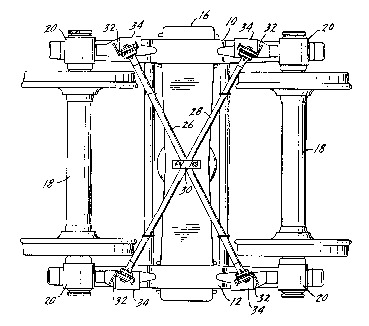
Fig. 2 is a bottom plan view of the truck of Fig. 1;
Fig. 3 is an enlarged side view of the mounting bracket
supporting the diagonal cross braces;
Fig. 4 is a bottom view of the end block and mounting
bracket; and

2130051
Fig. 5 is a side view, looking up at 45~ to the
horizon, on an enlarged scale, showing the mounted end block and
its relationship to the scan area of a hot box detector and the
truck roller bearing and axle.
DESCRIPTION OF THE PREFERRED EMBODIMENT
In the drawings, a diagonally braced truck of the type
disclosed in U.S. Patents 4,570,544 and 5,243,920 is illustrated
in Figs. 1 and 2. There are side frames 10 and 12, each of which
has a window within which are mounted load springs 14. The
springs 14 support a bolster 16 as is conventional. There are a
pair of wheelsets 18 each of which has roller bearings 20 on
which are mounted roller bearing adapters 22. The adapters 22
support the side frame on the wheelsets.
As is known in the art, it is common practice for
railroads to utilize hot box detectors to detect overheated
roller bearings. Such detectors are normally mounted outboard of
a rail and have an upward scan path which is at approximately 45~
to the horizontal. The typical scan path for a hot box detector
is illustrated in Fig. 1 and is bounded by the broken lines 24
which extend from the top of the rail up to the left-hand roller
bearing of the truck.
The present invention is particularly concerned with an
end block design which will not interfere with the scan path of
the hot box detector.
The truck illustrated in Figs. 1 and 2 has diagonal
cross braces 26 and 28, each of which extends from an area

2130057 ~l
generally adjacent one corner of one side frame to a diagonally
opposite position on the other side frame. The mounting
arrangement for the end of each cross brace is identical and only
one will be described in detail. As shown in Fig. 2, the cross
S braces are attached to each other via an integrated clamp 30
which extends over the crossing diagonal braces and to the
respective side frames via a huckbolt 58.
The mounting arrangement for each end of each diagonal
cross brace is illustrated in Figs. 3, 4 and 5. There is a
mounting bracket 32 which is attached by a base plate 34 to the
side frame, conventionally by welding or the like. The bracket
32 has an opening 36 in one wall 38 thereof. The end block is
illustrated at 40 and has a circular flange 42 and an axially
extending nose 44 with fillets 46 being integral with both the
flange and the nose for support. The nose 44 has a portion of
reduced diameter, indicated at 48, which extends within the
hollow interior of the cross braces 26 and 28 and thereby mounts
the cross braces to the end block.
There is a first elastomeric mounting element 50 which
is seated upon holding ring 52 which is welded to wall 38 of the
mounting bracket 32. On the opposite side of wall 38 there is a
similar elastomeric mounting element 54 and a holding ring 56
welded to wall 38. A bolt 58, washer 60, and locking plate 62
complete the support for the end block, with the bolt 58 passing

2130057
through the mounting hole 36, elements 50, 52, 54, 56, and wall
38 of mounting bracket 32. Thus, the entire assembly is bolted
to the mounting bracket with the end block extending toward the
interior of the truck to mount to hollow diagonal cross braces 26
and 28.
Illustrated in Fig. 5 is the roller bearing 20 and the
associated axle of a wheelset 18. Also shown in this figure is
the location of the mounting bracket and the end block, as they
would be located and positioned by the side frame. In broken
lines at 64 is the A.A.R. assigned minimum scan area of the hot
box detector. The long slender nose 44 of the end block is
specifically designed so that there is minimum overlap between
the end block and the scan area 64 of the hot box detector. In
prior art end blocks there was substantial interference or
overlap between the scan area and the end block which prevented
appropriate utilization of the hot box detector. The present
end block having an integral circular flange, long slender nose
and supporting fillets is formed and adapted to provide the
necessary secure mounting for the diagonal cross braces, but yet
avoid interference with the scan path of the hot box detector.
Whereas the preferred form of the invention has been
shown and described herein, it should be realized that there may
be many modifications, substitutions and alterations thereto.

Representative Drawing
A single figure which represents the drawing illustrating the invention.
Administrative Status

2024-08-01:As part of the Next Generation Patents (NGP) transition, the Canadian Patents Database (CPD) now contains a more detailed Event History, which replicates the Event Log of our new back-office solution.

Please note that "Inactive:" events refers to events no longer in use in our new back-office solution.

For a clearer understanding of the status of the application/patent presented on this page, the site Disclaimer , as well as the definitions for Patent , Event History , Maintenance Fee  and Payment History  should be consulted.

Event History

Description Date
Inactive: Expired (new Act pat) 2014-08-12
Inactive: Office letter 2007-03-16
Inactive: Corrective payment - s.78.6 Act 2007-01-31
Inactive: IPC from MCD 2006-03-11
Inactive: Entity size changed 2002-08-28
Grant by Issuance 1998-08-25
Pre-grant 1998-04-16
Inactive: Final fee received 1998-04-16
Notice of Allowance is Issued 1997-10-24
Letter Sent 1997-10-24
Inactive: Application prosecuted on TS as of Log entry date 1997-10-21
Inactive: Status info is complete as of Log entry date 1997-10-21
Inactive: IPC removed 1997-10-02
Inactive: First IPC assigned 1997-10-02
Inactive: IPC assigned 1997-10-02
Inactive: Approved for allowance (AFA) 1997-10-01
Application Published (Open to Public Inspection) 1996-01-06
All Requirements for Examination Determined Compliant 1995-09-01
Request for Examination Requirements Determined Compliant 1995-09-01

Abandonment History

There is no abandonment history.

Maintenance Fee

The last payment was received on 

Note : If the full payment has not been received on or before the date indicated, a further fee may be required which may be one of the following

  • the reinstatement fee;
  • the late payment fee; or
  • additional fee to reverse deemed expiry.

Please refer to the CIPO Patent Fees web page to see all current fee amounts.

Fee History

Fee Type Anniversary Year Due Date Paid Date
MF (application, 3rd anniv.) - small 03 1997-08-12 1997-07-28
Final fee - small 1998-04-16
MF (application, 4th anniv.) - small 04 1998-08-12 1998-07-24
MF (patent, 5th anniv.) - small 1999-08-12 1999-07-28
MF (patent, 6th anniv.) - small 2000-08-14 2000-08-04
MF (patent, 7th anniv.) - small 2001-08-13 2001-07-30
MF (patent, 8th anniv.) - standard 2002-08-12 2002-08-08
MF (patent, 9th anniv.) - standard 2003-08-12 2003-08-07
MF (patent, 10th anniv.) - standard 2004-08-12 2004-07-19
MF (patent, 11th anniv.) - standard 2005-08-12 2005-07-06
MF (patent, 12th anniv.) - standard 2006-08-14 2006-07-17
2007-01-31
MF (patent, 13th anniv.) - standard 2007-08-13 2007-07-25
MF (patent, 14th anniv.) - standard 2008-08-12 2008-07-17
MF (patent, 15th anniv.) - standard 2009-08-12 2009-07-21
MF (patent, 16th anniv.) - standard 2010-08-12 2010-08-11
MF (patent, 17th anniv.) - standard 2011-08-12 2011-07-12
MF (patent, 18th anniv.) - standard 2012-08-13 2012-08-08
MF (patent, 19th anniv.) - standard 2013-08-12 2013-07-30
MF (application, 2nd anniv.) - small 02 1996-08-12
Owners on Record

Note: Records showing the ownership history in alphabetical order.

Current Owners on Record
STANDARD CAR TRUCK COMPANY
Past Owners on Record
JOHN T. SARNICKI
THOMAS R. BERG
Past Owners that do not appear in the "Owners on Record" listing will appear in other documentation within the application.
Documents

To view selected files, please enter reCAPTCHA code :


To view images, click a link in the Document Description column. To download the documents, select one or more checkboxes in the first column and then click the "Download Selected in PDF format (Zip Archive)" or the "Download Selected as Single PDF" button.

List of published and non-published patent-specific documents on the CPD .

If you have any difficulty accessing content, you can call the Client Service Centre at 1-866-997-1936 or send them an e-mail at CIPO Client Service Centre.


Document
Description 
Date
(yyyy-mm-dd) 
Number of pages   Size of Image (KB) 
Description 1997-09-10 5 175
Claims 1997-09-10 2 77
Cover Page 1996-04-29 1 16
Abstract 1996-01-06 1 19
Description 1996-01-06 5 184
Claims 1996-01-06 3 89
Drawings 1996-01-06 2 75
Cover Page 1998-08-12 1 57
Representative drawing 1998-04-03 1 27
Representative drawing 1998-08-12 1 17
Commissioner's Notice - Application Found Allowable 1997-10-24 1 165
Correspondence 1998-04-16 1 44
Correspondence 2007-03-16 1 14
Fees 1996-07-24 1 37
Prosecution correspondence 1995-09-01 1 38
Prosecution correspondence 1997-07-23 2 49
Courtesy - Office Letter 1995-10-03 1 47
Prosecution correspondence 1995-11-21 2 92
Examiner Requisition 1997-01-28 2 75