Note: Descriptions are shown in the official language in which they were submitted.
2~
Filter apparatus for flowable material,
in particular for synthetic plastics melts containing impurities
The invention relates to a filter apparatus for flowable material
containing solid particles, in particular to synthetic plastics melts
oontaining impurities, comprising a housing in which a filter element is
disposed, said filter element being rotational symmetrical to an axis and
having on its periphery a plurality of penetration openings similar to
holes for the filtered matter, said housing comprising an inlet opening for
supplying the material to be filtered to the filter element to the outer
side of its periphery, so that the filtered material penetrates the filter
element from the outside to an inner hollow space being in flow connection
with an outlet opening of the housing, whereas for a continuous
removal of the residual matter from the periphery of the filter element a
scraper element is provided which is disposed coaxially to the filter
element and engages the outer periphery of the filter element and follows
its curvature, so that the r~sidual matter is carried through an
annular gap disposed between the filter element and the housing with a
component of its motion directed in axial direction of the filter element
towards a separate exit, and wherein the filter element for its roation
around its axis is connected to a drive means.
A filter apparatus of this kind is known for a mud suction carriage
tEP-A 164,004)~
Another filter apparatus has become known from the EP-A 411,163.
Within this known construction a flange disposed at one front end of the
filter element is fixed to the housing and scraper element that is wound
around the outer periphery of the filter element in form of a spiral strip
is rotated by means of a driving shaft around the axis of the hollow
i ~
213~10~
- 2 -
cylindrical filter element. Thereby, on the one hand, the residual matter
is scraped off the outer periphery of the filter element, and, on the other
hand, the residual matter is conveyed towards the exit opening of the
housing. This known construction has the disadvantage that the scraper
element that is helically wound around the filter element tends to adhere
to the outer periphery surface of the filter element, because reactien
forces act onto this scraper element which are caused by the impurities
taken off and by the friction between the filter element and the scraper
element wound around it. If one tries to avoid this disadvantage by a
correspondingly increased gap between the inner surface of the helical
strip and the outer periphery of the filter element, then the scraping
effect of the spiral strip is no more sufficient. This disadvantage can
reliably be avoid0d only then if the spiral strip is provided with a great
wall thickness, but this is of detrimental influence upon the entire
dimension, in particular to the outer diameter of the housing accommodating
the filter element. Further, no self adjustment is possible in order to
obtain a clearsnce-free interaction between the filter element and the
scraper element.
The invention has at its object to reliably avoid the described
disadvantages without increasing the diameter of the housing. The invention
solves this task by the features that the scraper element is divided into
several partial elements, which are resiliently abutted in radial direction
of the filter element within the housing confining the annular gap on its
outside, and each of which engages the filter element along a helix section
or a spiral line section only over a section of the axial length of the
filter element and is hold in the housing secured against rotation, the
partial elements, however, extending along a single-flight or multiple-
'' '~ 3 ~ ;~ -
flight helix or spiral line. Whereas, therefore, within the lastly
described known construction the filter element stands still and the ;'
,.,~.: .
spiral-shaped scraper element is rotated, within the inventive construction
the disposition is inverse, that means, the filter element is rotated and
the partial elements of the scraper element stand still. Thus, the scraper
element can no more jam, neither to the filter element nor to the housing
and the scraper element can be disposed so thin that the annular space
between tha outer periphery of the filter element and the inner periphery
of the housing is just sufficient to reliably move-off the impurities.
Thereby and by the partial embedding of the partial elements of the scraper
element in the wall of the housing, an increase of the housing diameter is
avoided. This advantage is also given in comparison with the construction
according to the initially mentioned EP-A 164,004 as well as in comparison
to a further known construction (EP-A 78û64) in which the scraper ~ nL
in form of several hydraulically resiliently abutted partial elements
engages the filter element from the inner side.
Within the inventive construction, there are no difficulties to
rotate the filter element around its longitudinal axis, and for doing this,
the filter element must not be particularly thick. The subdivision of the
2û scraper element into several partial elements distributed over the length
of the filter element enables one, if proper adjustment is given, to obtain
different scraping effects over different parts of the filter element and/
or to obtain the desired clearance between the filter element and the
partial elements of the scraper element without any problem.
The invention enables one to maintain the geometric structure of the
known filter elements, or to change it. in the first case, according to the
invention, the filter element is of hollow cylindrical shape and is connec-
~ ..
, ,~ , ., ~ i !, ' .
2 ~ 3 0 1 0 ~
- 3a -
ted at its one, closed front end to the shaft of a drive means, if desired
by means of a coupling. In the last case, according to the invention, the
filter is of conical or frusto-conical shape and is connedted at its one end
to the shaft of a drive means. As a rule, the first named construction is to
be preferred by clearness purposes and by the ground of a more simple con-
struction.
Within the spirit of the invention, a resilient action of ~he partial
elements of the scraper element onto the filter element can be obtained by
abutting the partial elements of the scraper element resiliently in radial
direction of the filter element, preferably by means of pressure springs
engaging the scraper element from the outside. For this, a particularly
:
suitable construction consists according to the invention in that each
partial element carries at least one radially disposed pin on its outer
surface, which pin is guided in a radial bore of the housing and is pressed
inwardly by a spring inserted between the end of this bore and the front
end of the pin.
Suitably, the exit opening is disposed in the region of that front
end of the filter element that does not face the discharge opening for the
filtered material. In the region of the exit opening and/or in the
channel, a conveyor element, in particular a screw, can be provided for
transporting off the impurities. In such a manner, the scraper element or
its partial elements by which the transport of the impurities to the exit
opening is made, are relieved from reaction forces. This screw, according
to a preferred embodiment of the invention, can be constituted by a section
of the driving shaft, said section at the same time serving as a sealing.
This section may according to the invention, be surrounded by a cooling
means for the purpose to transport the impurities to the outside in
~ ,.,.!,,,,,.,,,.,,", ,", ,~,", ,~",,., ,""," ~, "", ,~
~t ' ~ ~ 4 - ~1 3 ~1 0 ~ ;~
a cooled condition.
The material to be filtered is supplied under pressure and
pressurizes the closed front end of the filter element, so that these
forces tend to shift the filter element in direction of the pressure force.
This pressure can be compensated at least par-tially by the featu~e that the
driving shaft connected to the front end of the filter element has a
2 1 3 0 1 0 ~
-- 5 --
smaller diameter than the outer diameter of the cylindrical filter
element. By the so formed annular surface a counter-pressure is exerted
that makes the said compensation.
Since the filter element within the inventive construction has to
withstand the torsion exerted by the driving shaft, a partioular suitable
embodiment within the spirit of the invention consists in that the filter
element consists of a screen carrier member radially penetrated by a
plurality of channels, the outer periphery of this screen carrier member
being engaged by a cylindrical screen which is provided with a plurality
of openings, the diameter of which being smaller than that of the
channels. The real filter action, therefore, is done by the screen openings
of the screen element, the impurities being scraped off from the outer
periphery of the screen element by the scraper element or its sections,
respectively. The screen element can be shrunk on the screen carrier member
in a simple manner.
The inventive construction is particularly suitable for filtering
synthetic plastics material melts, in particular in the recycling field.
However, it can also be used with advantage in other technical fields where
solid particles must be filtered from a liquid carrying these particles,
for example fruit juices, for the filtration of oils and so on.
In the drawings embodiments of the invention are schematically shown
by way of examples. Fig.1 shows a longitudinal section through a first
embodiment. Fig.2 shows a section along the line II-II of Fig.1. Fig.3
shows the detail III of Fig.1 in a greater scale. Figs.4 to 7 each show a
further embodiment in longitudinal section. Fig.8 shows a section through a
section of the filter element in an enlarged scale.
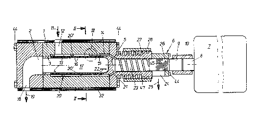
Within the embodiment according to- Fig.1 a substantially hollow
213~10~ ~
cylindrical housing 1 is provided, in the hollow space 2 of which a
substantially cylindrical filter element 3 is bearingly supported for
rotation around its longitudinal axis 4. This filter element 3 is closed on
its one front end 5 and is there connected for co~mon rotation to the shaft
8 of a drive means 6. This drive means 6 comprises a motor 7 provided with
a gearing, the driven shaft 8 thereof is coupled by means of a coupling 10
to a shaft 9 connected to the front end 5 of the filter element 3. The
material to be filtered is in-troduced in direction of the arrow 11 through
an inlet opening 12 into the housing 1 and enters there a narrow annular
gap 13 between the inner periphery surface 14 of the housing 1 and the
outer periphery surface 15 of the filter element 3. This filter element 3
is provided with a plurality of penetration openings 16 for the filtered
material, which openings are constituted by holes that are so small that
the impurities to be r~-~~,ved from the material to be filtered are retained.
The filtered material penetrates the penetration openings 16 and reaches
the cylindrical hollow space of the filter element 3 connected to a
discharge opening 18 of the housing 1 through which the filtered ~aterial
leaves the apparatus in direction of the arrow 19. The impurities retained
by filter element 3 gather on the outer periphery surface 15 of the filter
element 3 and are transported from there by means of a stillstanding
scraper element 20 in direction towards the closed front end 5 of the
filter element 3. For this, the scraper element 20 extends in partial
elements 20' in the manner of a helix line around the outer surface 15 of
: , .
the filter element 3, suitably wlth a constant lead of the helix line. Each
one of the partial elements 20', therefore, engages with its scraping edge
the filter element 3 along a short section of the helix line, the scraplng
edges, therefore, follow the curvature of the filter element 3. All
:'' :' '
': : 2l 30104 ~:
scraping edges of the single partial elements 20' are directed to the same
side, so that all partial elements move the residual matter towards the
closed front end of the filter element 3. All partial elements of the
scraper element 20 are secured on the housing 1 against being taken along
by the filter element, therefore, the partial elements 20' do not rotate
together with the filter element. ~y the rotation of the filter element 3
along its longitudinal axis 4, however, a component of the motion directed
in direction of the axis 4 is exerted on the impurities in addition to the
scraping action, which component transports the impurities towards the
front end 5. The impurities reach there a frusto-conical annular space 21
which is formed by the fact that the shaft 9 has a smaller diameter than
the outer peripheral surface 15 of the filter element 3. This reducing of
the diameter has the following sense: The material to be filtered is
supplied under pressure through the inlet opening 12 and has sufficient
pressure also within the hollow space 17 in order to exert a substantial
pressure component in direction of the arrow 22 onto the closed front end 5
of the filter element 3, so that the material to be filtered tries to shift
the filter element 3 and the shaft 9 connected thereto to right (Fig.1).
This pressure can at least partially be compensated by the counter-pressure
exerted onto the frusto-conical section of the front end S of the filter
element by the also pressurized impurities which are carried away in the
annular space 21. This counter-pressure is supported by the
counter-pressure of a screw 23 which constitutes a section of the driving
shaft 9. In such a manner the ideal condition, that means no axial forces,
can be obtained, if the dimensions are proper chosen. The housing of the
screw 23 forms a channel 47 for carrying off the impurities which are
transported by the screw 23 from the annular space 21 through the channel
!, ' ', i ~
' . ,~''':~''..:. , ~ . ., , ~ ' :
.~ :~;. , ~' :, . ' '' , ' ' ' ' '; , ~ ~ ' '
' ~
- ~-13~10~
47 towards an exit 24 which extends laterally from the housing of the sorew
23 and through which the impurities discharge in direction of the arrow 25.
In that section of the shaft 9 which with respect to the exit 24 is
disposed opposite the screw 23, a further scre~ 26 is provided which has
a direction of threads opposite to that of the screw 23 so that it acts as
a sealing. The section 27 of the housing 1 that surrounds the screw 23
may be provided on its outer periphery with cooling ribs and, in addition
thereto, with a cooling means 28.
The scraper element 20 with its partial elements may follow a
single-flight helix having a constant lead. However, this scraper element
2û may also be multiple threaded. In each case, the partial elements 20' of
the scraper element 20 are secured on the housing and always engage the
filter element 3 only along a section of the axial length thereof. Each of
these partial elements 20' is resiliently supported within the housing 1 so
that in a proper disposition all of ~hese partial elements 20' engage the
outer peripheral surface 15 of the filter element 3 with the same pressure.
For this, each partial element 20' carries at least one radially disposed
:: ~
pin 29 (Fig.3) which is guided in its longitudinal direction within a
radial bore 30 of the housing 1. The bore 30 is closed at its one end and a
pressure spring 31 engages this end and tries to press the pin 29 and
therefore the related partial element 20' of the scraper element 20 - -~
inwardly in radial direction. If desired, the pressure of the spring 31 may
be adjustable, suitably by means of an adjustable abuttment member. The
single partial elements 20' of the scraper elements have front surfaces
facing the filter element 3 and being chamfered in transport direction so
that the edge 33 exerting a scraper action onto the filter element 3 faces
the closed front end 5 of the filter element 3. ~
' ' ,:
'', ', , 2~3~10~ ~
- 9 -
The housing 1 may on its outside be surrounded by a heating strip 32
in order to maintain the temperature of the supplied synthetic plastics
material melt at the desired temperature.
In Fig.8 the construction of the filter element 3 is shown in
detail. It has a screen carrier member 34 that is penetrated by a plurality
of radial channels 35 for the filtered material. The outer surface 36 of
the screen carrier member 34 is engaged by a screen cylinder 37 that has a
thickness which is smaller in comparison to that of the screen carrier
member 34, the screen cylinder suitably being shrunk onto the screen
carrier member 34. The screen cylinder 37 has openings 38, the number of
which is greater than that of the channels 35. The openings 38 may be
produced by laser machining. The diameter of the openings 38 is
substantially smaller than that of the channels 35 so that the openinys 38
can be passed by the synthetic plastics material melt only, but not by the
impurities thereof. Suitably, the channels 35 enlarge towards the screen
carrier member 37 in order to make as much openings effective as possible.
The enlargements 46 of the channels 35 can be produced in a simple manner
by machining screw threads, particularly having a trapezoidal cross
section, or annular grooves at the outer surface 36 of the screen carrier
member 34. The screen member 37 is then fixed to the crests of these screw
threads or, respectively, to the ribs remaining between the annular
grooves.
Within the embodiment according to Fig.4, the rotating filter
element 3 and the shaft 9 which in a section is formed as a screw Z3,
have substantially the same outer diameter. If the reaction force exerted
onto the shaft 9 to the left (Fig.4) by the screw 23 is not
sufficiently great, there will be an axial force acting onto the filter
~13V~ o~
- 10 -
element 3 towards the right, a corresponding pressure of the material
supplied via the inlet opening 12 provided. It is to be recommended
therefore, to use such an apparatus only then, if the pressure of the
supplied material to be cleaned is low.
According to the embodiment of Fig.5, the inlet opening 12 of the
housing 1 is provided with an enlargement 39 facing the filter element 3
and extending in axial direction of the filter element 3 over nearly the
entire length thereof. Such an enlalgam~n~ which is formed like a slot in
the housing 1, forms a distributor for the material supplied which
distributes this material ùver the entire length of the filter element 3.
This enhances the filter action of the filter element 3. Further, the
scraper element 12 or, respectively, its partial elements 20' continue into
the section 27 of the housing 1 up to the exit opening 24, so that-the
scraper element 20 carries out also the discharge of the deposited
impurities. Therefore, the screw 23 can be omitted. A li~ited counter
thrust onto the filter element 3 towards the left can take place by the
worm 26 serving as a sealing.
The embodiment according to Fig.6 is similar to that of Fig.5, but
the exit 24 for the impurities is disposed closer to the closed front end 5
of the filter element 3 and - when seen in flowing direction of the
impurities - is disposed before the cooling means 28. This causes that the
impurities are quicker carried off. Further, a tube 40 is inserted into the
exit 24, and a valve 41 is disposed in that end of the tube 40 that
protrudes from the housing 1 or, respectively, from the heating strip 32.
Thereby, the impurities carried off can be d~ained off in portions.
The embodiment according to Fig.7 is similar to that of Fig.6,
however, a conveyor element in form of a screw 42 driven by a separate
,, .
~3l~10~
' , ~ .
11 -
drive means is disposed within the tube 40 instead of the valve 41, and
this screw 42 carries off the impurities to the outside through an outlet
opening 43 disposed at the side of the tube 40.
For reasons of a simple assembling, in all embodiments the housing 1
is composed of at least two parts connected to each other by means of
screws 44. Thereby it is possible to produce in the housing 1 curved guide
walls 45 leading to the laterally extending openings 18, 24, which guide
walls produce a smooth deviation of the stream of the flowing material and
prevent, therefore, that single portions of the treated material remain for
a longer time within the apparatus and by this are thermically damaged.
Within the embodiments according to Figs.6 and 7 the guide wall 45 is
omitted in the region of the exit 24.
"'' ~ ,.