Language selection

Search

Patent 2130204 Summary

Third-party information liability

Some of the information on this Web page has been provided by external sources. The Government of Canada is not responsible for the accuracy, reliability or currency of the information supplied by external sources. Users wishing to rely upon this information should consult directly with the source of the information. Content provided by external sources is not subject to official languages, privacy and accessibility requirements.

Claims and Abstract availability

Any discrepancies in the text and image of the Claims and Abstract are due to differing posting times. Text of the Claims and Abstract are posted:

  • At the time the application is open to public inspection;
  • At the time of issue of the patent (grant).
(12) Patent: (11) CA 2130204
(54) English Title: DRY SCRUBBER WITH CONDENSING HEAT EXCHANGER FOR CYCLE EFFICIENCY IMPROVEMENT
(54) French Title: EPURATEUR A SEC AVEC ECHANGEUR DE CHALEUR A CONDENSATION POUR RENDEMENT AMELIORE DU CYCLE
Status: Expired and beyond the Period of Reversal
Bibliographic Data
(51) International Patent Classification (IPC):
  • F28B 1/00 (2006.01)
  • B01D 46/04 (2006.01)
  • B01D 53/34 (2006.01)
  • B01D 53/50 (2006.01)
  • F23J 15/00 (2006.01)
  • F23J 15/04 (2006.01)
  • F23J 15/06 (2006.01)
  • F23L 15/00 (2006.01)
  • F23L 15/04 (2006.01)
(72) Inventors :
  • SMITH, J. WILLIAM (United States of America)
(73) Owners :
  • THE BABCOCK & WILCOX COMPANY
(71) Applicants :
(74) Agent: SMART & BIGGAR LP
(74) Associate agent:
(45) Issued: 1997-10-14
(22) Filed Date: 1994-08-08
(41) Open to Public Inspection: 1995-02-11
Examination requested: 1994-08-08
Availability of licence: N/A
Dedicated to the Public: N/A
(25) Language of filing: English

Patent Cooperation Treaty (PCT): No

(30) Application Priority Data:
Application No. Country/Territory Date
104,974 (United States of America) 1993-08-10

Abstracts

English Abstract


A system for controlling sulfur dioxide (SO2) in a flue
gas produced by a boiler comprises an air heater connected to
the boiler for cooling the flue gas produced by the boiler.
A dry scrubber is connected to the air heater and a slurry
source for receiving the heated flue gas and a slurry in order
to remove SO2 from the flue gas. A particulate collector is
connected to the dry scrubber in order to collect particles
from the flue gas. Heat is recovered from the flue gas by
connecting a condensing heat exchanger to the particulate
collector; and a condensate recycler is connected to the
condensing heat exchanger and the slurry source for reducing
the water requirements for the system.


French Abstract

Système pour contrôler le dioxyde de soufre (SO2) dans un gaz de combustion produit par une chaudière comprenant un réchauffeur d'air raccordé à la chaudière pour refroidir le gaz de combustion produit par la chaudière. Un épurateur à sec est raccordé au réchauffeur d'air et à une source de boue pour recevoir le gaz de combustion chauffé et la boue pour extraire le SO2 du gaz de combustion. Un collecteur de particules est raccordé à l'épurateur à sec pour recueillir les particules du gaz de combustion. La chaleur est récupérée du gaz de combustion en raccordant un échangeur-condenseur au collecteur de particules; et une unité de recyclage de condensats est raccordée à l'échangeur-condenseur et à la source de boue pour diminuer les besoins en eau du système.

Claims

Note: Claims are shown in the official language in which they were submitted.

THE EMBODIMENTS OF THE INVENTION IN WHICH AN EXCLUSIVE
PROPERTY OR PRIVILEGE IS CLAIMED ARE DEFINED AS FOLLOWS:
1. A system for controlling sulfur dioxide (SO2) in a
flue gas produced by a boiler, the system comprising:
an air heater connected to the boiler for cooling
the flue gas produced by the boiler;
a slurry source;
a dry scrubber connected to the air heater and the
slurry source for receiving the heated flue gas and a slurry
from the slurry source for removing SO2 from the flue gas;
particulate collection means connected to the dry
scrubber for collecting particles from the flue gas;
a condensing heat exchanger connected to the
particulate collection means for recovering heat from the flue
gas; and
condensate recycle means connected to the condensing
heat exchanger and the slurry source.
2. The system according to claim 1, including a stack
connected to the condensing heat exchanger for passing the
flue gas from the system.
3. The system according to claim 1, wherein the
condensing heat exchanger is cooled by air.
4. The system according to claim 1, wherein the
condensing heat exchanger is cooled by water.

5. The system according to claim 3, including means for
channeling air from the condensing heat exchanger connected to
the air heater for introducing heated air into the boiler.
6. The system according to claim 5, wherein the
particulate collection means comprises a baghouse.
7. The system according to claim 3, wherein a fan is
connected to the condensing heat exchanger for cooling the
air.
8. The system according to claim 4, wherein a fan is
connected to the air heater.
9. The system according to claim 4, wherein the
particulate collection means comprises a baghouse.
10. A method for removing sulfur dioxide (SO2) from a
flue gas produced by a boiler, the method comprising:
cooling the flue gas produced by the boiler;
providing a slurry source to a dry scrubber;
removing SO2 from the flue gas in the dry scrubber;
collecting particulate from the flue gas;
recovering heat from the flue gas in a condensing
heat exchanger; and
recycling condensate produced by the condensing heat
exchanger back into the system.
11. The method according to claim 10, wherein the
condensing heat exchanger is cooled by air.

12. The method according to claim 10, wherein the
condensing heat exchanger is cooled by water.
13. The method according to claim 11, including
channeling air from the condensing heat exchanger back into
the boiler.

Description

Note: Descriptions are shown in the official language in which they were submitted.


2 ~ 3 ~ ,. 3 ~ .SE 5353
FOR C~ ~ R~FT~ :~y ~MPR~VRMRNr
FT~-n ~N~ RA~K~--~n OF TU~. lNVh:NI-~
e present inV~nt;~n re1~t~s in general to power plants
and their ~m;.~.s;orLs, and in partic~lar to a new and useful
system and meth~ for incr~;n~ the efficiency of power
pl~nt~ using c~ n~ heat ~ 3~, N~ S .
It is well-known ~ ~he power plant field to use a dry
scrubber for ~llLlol 1; n~ ~m; ~; nn~ of sulfur dioxide (SC~)
o~ntA;n~ within the flue gas pro~n~e~ by these pl~nts~ It is
a c~ problem or process constraint for power ~l~nts
employing dry scrukbers to m~; nt~;n a m; n;~lm gas tem~erature
for the dry scrukber which is re~uired for a flue gas
scrl-hh;n~ ~o~s Ihis m;n;mllm ga~ t~,~ t11re is
15 ~,5~hl; ~h~ by the requir~.~..ls for eVd~dLing water in a
scrubber 81urry in the dry scrubber while still achieving the
desired t~.~ re ~n the scrubber process.
As a ~n~r~l rule, the greater the sulfur c~nt~nt of the
flue gas and the greater the required SC~ rem~val effi-iency,
the h;gh~r t-h-e m;n;ml~ gas temperature is required for the dry
scr~bber. This ~;n;~n~ gas te~perature requi.~,~ sets a
limit on the achievable efficiency for the boiler, i.e. the

~:
~ Case 5353
ability to m;n;m; 7e the heat loss in the exhaust gas, and thus
limits the efficiency of the cycle.
U.S. Patent 4,956,162 to Smith et al. discloses a known
system for removing S~ from a flue gas. This system,
however, has a limited cycle efficiency due to the m;n;mllm gas
temperature requi~"~..~s as described above.
Presently, there is no known system or method which can
improve the cycle efficiency for a dry scrubber system.
sr~MM~RY OF ',~'HI-: INVl':~Ll~lN
m e present invention overcomes the cycle limitations
c~l~ ly found in known systems by providing additional heat
recovery in a unique system which also comprises a ~on~n~ing
heat exchanger.
m e present inv~nt-~n provides a system for controlling
sulfur dioxide (SC~) in a flue gas produced by a boiler and
comprises an air heater conn~cte~ to the boiler for cooli~g
the flue gas pro~ e~ by the ho;l~r A slurry source is also
pro~ided. A dry scrubber is connPcte~ after the air heater
and the slurry source for receiving the cooled flue gas and a
slurry in order to ~-~v~ SC~ from the flue gas. Partic~ te
collec~;n~ means, such as a baghouse, is c~nn~cted to the dry
scrubber for collecting par~; rl e-s from the flue gas. A
con~n~;n~ heat ~ "(~r is c~nn~cte~ to the particnl~te
collection means for ~e~v~ling heat from the flue gas which,
; 2S in turn, ill~L~V~S the cycle ~ff;c;ency of the system.
~Jnn~n~te recycle me~ns is also provided for re~n~;ng the
water requir~"~,lls of the system.
It is an object of the present inV~nt;on to provide a
system for ~v~lL~ll;n~ SC~ in a flue gas for impro~ing the
cycle efficiency of the ~ystem.
It is another object of the present invention to provide

~13 o ,~, /1 Case 5353
a system for controlling SO2 in a flue gas which reduces the
water requir~m~ntfi for the system.
The various features of novelty which characterize the
invention are pointed out with particularity in the cl~
annexed to and forming a part of this disclosure. For a
better underst~n~;ng of the invention, its operating
advantages and specific objects attA;ne~ by its uses,
reference is made to the acccmpanying drawings and descriptive
matter in which a preferred embo~;m~nt of the invention is
illustrated.
~RI~F ~Kl~Ll~h~ OF THE D~T~GS
In the drawings:
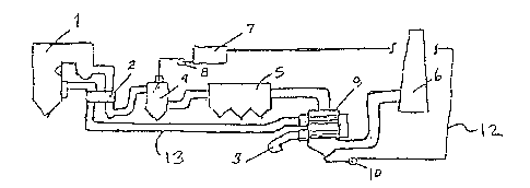
Fig. 1 is a schematic view of a known SO2 re~ val system;
Fig. 2 is a schematic view of an SO2 removal system
according to the present invention; and
Fig. 3 is a schematic view of a second embo~ nt of an So2
removal system according to the present invention.
-~lV~ OF TR~ ~ :,) ~MRnnTMFNTs
Fig. 1 illustrates a known system for removing SO2 from
the flue gas pr ~ l~-e~ by a boiler 1. An air heater 2 is
c~nn~cted to the ho;l~r 1 for cooling the flue gas, while
h~t;ng the combustion air, which is pro~l~e~ and passed by
the boiler 1. The cooled flue gas is ~hAnn~led to a dry
scrubber 4 for removing SC~ from the flue gas.
A slurry source 7, such as a slurry tank, prcvides a
slurry through a slurry pump 8 into the dry scrubber 4 for
removing the SC~ from the flue gas. A h~h~ e 5 is oonn~cted
to the dry scrubber 4 in order to oollect particles from the
flue gas after the scrubbing process has been perfonmed in the
dry scrubber 4. A stack 6 is c~nn~cted to the baghouse 5 for

'~ i
h Case 5353
v~nt;n~ SC~-free e~haust from the system. A forced draft (FD)
fan 3 is ~onn~ted to the air heater 2 and the boiler 1.
The present invention provides a means for overcoming the
cycle limitations of known systems by providing additional
heat recovery for the system and by reducing the water
requi~ s for the system.
The same reference numerals are used to designate the
same or functionally ~im;l~r parts. According to the present
invention, Fig. 2 illustrates a novel system for removing SO2
from the flue gas of a boiler 1. S;mi 1 ~r to the known
systems, an air hP~t~r 2 is conn~cted to the boiler 1 for
cooling the flue gas produced ~y the boiler 1, which in turn,
is provided to the dry scrubber 4 which receives the slurry
from the slurry source 7 through the slurry pump 8. Once SO2
1~ is removed from the flue gas in the dry scrubber 4, a
particulate collector, such as a baghouse 5, is used to
collect particles frcm a flue gas.
U~like the known systemLq, a co~n.q;n~ heat e~h~n~er 9
is c~n~cted to the particulate collector 5 in order to
recover heat for the system through primarily cnn~n~; n~ water
vapor in the flue gas stream which has left the dky scrubber
4. This water vapor c~n~nRe~ by the con~Pnqing heat
y~L 9 results from both the combustion products
- ~hyd~ and moisture in the fuel) and from water evaporated
in the dry scrubber 4.
The c.,..~ ing heat ex~h~er 9, illustrated in Fig. 2,
is air-cooled through the use of an FD fan 3 conn~cted to the
cnn~n~ln~ heat ~ 9. Fig. 3 illustrates a con~n~;ng
heat ~k~ly~ 9a which is water-cooled by a water source,
such as tl~rh;n~- c~n~n~te.
As ~hown in Figs. 2 and 3, con-l~n~at~ produced by the
c~ n~l~n~ing heat ~x~lklllye~s 9 (Fig. 2) and 9a (Fig. 3) i8
,
.

' ~
Ca~e 5353
recycled by a con~n~te recycle ~h~nn~l 12 which is ronn~ted
to the slurry tank 7 and pumped by c~n~n~te return pump 10
in order to reduce the water requi~ fi for the dry scrubber
~ and the system in general. Also, a stack 6 is c~nn~cted to
S the c~ n~ing heat exchangers 9 and 9a, as shown in Figs. 2
and 3 respectively, in order to allow cleaned flue gas to exit
the system.
Fig. 2 illustrates an air ~h~nn~l 13 c~nnPcted to the
c~ n~ing heat exchanger 9 and the air heater 2 and the
boiler 1. Combustion air is first used as the working fluid
in the c~n~n~;ng heat exchanger 9 with the h~te~ air leaving
the heat exchangex 9 and being directed through air ~h~nnPl 13
to the air h~t~r 2, which is sim;l~r to an air heater of a
convent;~n~l system, which in turn, provides the heated air
back into the boiler 1. According the system disclosed by the
present invention, the heat recovered is eventually
transferred to the high pressure steam cycle of the system.
Fig. 3 also illustrates an FD fan 3 c~nn~cted to the heat
exchanger 2 and the boiler 1, s;mil~r to the known systems.
Although co.(l~,~;ng heat exchangers are not novel as heat
recovery devices, ~hey are, however, limited in their
application due to the relatiQn~h;p between the dew point
t~ rature of the gas mixture and the heat sink working fluid
temperature generally found in the power plant. In many
combustion processes, the dew point temperature is too low to
permit practical heat recovery by a c~n~n~;ng system. With
the inclusion of a dry scrubber, the dew point is elevated
which makes the ~n~n~ing heat e~ r m~re practical.
The present in~nt; nn allows for an increase in power
-30 generation efficiency cver known systems. The present
inv~nt;~n also provides for a means for re~nc;ng the make-up
~water requi~ for the dry scrubber in an SC~ removal
:; .

~ 2 3i~ Ca~ie 5353
siystem.
While a specific embo~ nt of the invention has been
shown and described in ~ ;1 to illustrate the application of
the principles of the invention, it will be understood that
the invention may be embodied otherwise without departing ~rom
such principles.

Representative Drawing
A single figure which represents the drawing illustrating the invention.
Administrative Status

2024-08-01:As part of the Next Generation Patents (NGP) transition, the Canadian Patents Database (CPD) now contains a more detailed Event History, which replicates the Event Log of our new back-office solution.

Please note that "Inactive:" events refers to events no longer in use in our new back-office solution.

For a clearer understanding of the status of the application/patent presented on this page, the site Disclaimer , as well as the definitions for Patent , Event History , Maintenance Fee  and Payment History  should be consulted.

Event History

Description Date
Inactive: IPC from MCD 2006-03-11
Time Limit for Reversal Expired 2003-08-08
Letter Sent 2002-08-08
Grant by Issuance 1997-10-14
Inactive: Application prosecuted on TS as of Log entry date 1997-08-07
Inactive: Status info is complete as of Log entry date 1997-08-07
Pre-grant 1997-04-30
Notice of Allowance is Issued 1997-03-04
Application Published (Open to Public Inspection) 1995-02-11
All Requirements for Examination Determined Compliant 1994-08-08
Request for Examination Requirements Determined Compliant 1994-08-08

Abandonment History

There is no abandonment history.

Maintenance Fee

The last payment was received on 

Note : If the full payment has not been received on or before the date indicated, a further fee may be required which may be one of the following

  • the reinstatement fee;
  • the late payment fee; or
  • additional fee to reverse deemed expiry.

Please refer to the CIPO Patent Fees web page to see all current fee amounts.

Fee History

Fee Type Anniversary Year Due Date Paid Date
Final fee - standard 1997-04-30
MF (application, 3rd anniv.) - standard 03 1997-08-08 1997-08-01
MF (patent, 4th anniv.) - standard 1998-08-10 1998-07-22
MF (patent, 5th anniv.) - standard 1999-08-09 1999-07-20
MF (patent, 6th anniv.) - standard 2000-08-08 2000-07-20
MF (patent, 7th anniv.) - standard 2001-08-08 2001-07-19
MF (application, 2nd anniv.) - standard 02 1996-08-08
Owners on Record

Note: Records showing the ownership history in alphabetical order.

Current Owners on Record
THE BABCOCK & WILCOX COMPANY
Past Owners on Record
J. WILLIAM SMITH
Past Owners that do not appear in the "Owners on Record" listing will appear in other documentation within the application.
Documents

To view selected files, please enter reCAPTCHA code :


To view images, click a link in the Document Description column. To download the documents, select one or more checkboxes in the first column and then click the "Download Selected in PDF format (Zip Archive)" or the "Download Selected as Single PDF" button.

List of published and non-published patent-specific documents on the CPD .

If you have any difficulty accessing content, you can call the Client Service Centre at 1-866-997-1936 or send them an e-mail at CIPO Client Service Centre.


Document
Description 
Date
(yyyy-mm-dd) 
Number of pages   Size of Image (KB) 
Drawings 1997-03-04 1 22
Cover Page 1997-10-03 1 50
Cover Page 1995-06-08 1 42
Abstract 1995-06-08 1 38
Claims 1995-06-08 3 108
Description 1995-06-08 6 300
Drawings 1995-06-08 1 32
Representative drawing 1997-10-03 1 7
Maintenance Fee Notice 2002-09-05 1 177
Fees 1997-08-01 1 36
Fees 1997-08-01 1 30
Fees 1996-07-22 1 26
Prosecution correspondence 1994-08-08 4 164
Prosecution correspondence 1994-11-14 1 26
Correspondence related to formalities 1997-04-30 1 35