Language selection

Search

Patent 2130883 Summary

Third-party information liability

Some of the information on this Web page has been provided by external sources. The Government of Canada is not responsible for the accuracy, reliability or currency of the information supplied by external sources. Users wishing to rely upon this information should consult directly with the source of the information. Content provided by external sources is not subject to official languages, privacy and accessibility requirements.

Claims and Abstract availability

Any discrepancies in the text and image of the Claims and Abstract are due to differing posting times. Text of the Claims and Abstract are posted:

  • At the time the application is open to public inspection;
  • At the time of issue of the patent (grant).
(12) Patent: (11) CA 2130883
(54) English Title: FOOT WEAR DRYING APPARATUS
(54) French Title: APPAREIL DE SECHAGE DE CHAUSSURES
Status: Expired and beyond the Period of Reversal
Bibliographic Data
Abstracts

English Abstract


The inventive idea refers to an apparatus that provides
divided air flows through flexible tubings to the inner
volume of moistured foot wear in order to dry them.


French Abstract

Cette invention concerne un dispositif à flexibles multiples servant à acheminer de l'air à l'intérieur de plusieurs chaussures humides pour les sécher.

Claims

Note: Claims are shown in the official language in which they were submitted.

THE EMBODIMENTS OF THE INVENTION IN WHICH AN EXCLUSIVE PROPERTY OR
PRIVILEGE IS CLAIMED ARE DEFINED AS FOLLOWS:
1. An electrically operated footwear dryer having: an elongated
housing, the housing adapted to be positioned on or near the floor of
a room; a fan in the housing near one end of the housing; a motor in
the housing for operating the fan; switch means for controlling
operation of the motor; air inlet means in the housing adjacent the
one end of the housing; at least two pair of air outlets at the other
end of the housing; and a flexible hose attached to each outlet of
each outlet pair, each hose long enough for insertion into a footwear
member resting on the floor, whereby operation of the fan will draw
air into the housing through the inlet means and force it out of each
air outlet pair through the hoses attached to the outlets in the
outlet pair and into a footwear pair the hoses are inserted in.
2. A dryer as claimed in claim 1 wherein the elongated housing is
constructed to stand on the one end on the floor.
3. A dryer as claimed in claim 1 including means for selectively
preventing air from exiting each pair of hoses not used to dry
footwear while at least one pair of hoses are drying footwear.
4. A dryer as claimed in claim 3 wherein the selective preventing
means comprise connector means on the end of one of the hoses of each
pair of hoses, the connector means allowing each pair of hoses to be
selectively connected to each other to prevent air from exiting the
hoses.
5. A dryer as claimed in claim 2 including means for selectively
preventing air from exiting each pair of hoses not used to dry
footwear while at least one pair of hoses are drying footwear.
6. A dryer as claimed in claim 5 wherein the selective preventing
means comprise connector means on the end of one of the hoses of each
pair of hoses, the connector means allowing each pair of hoses to be
selectively connected to each other to prevent air from exiting the
hoses.
3.

7. A dryer as claimed in claim 1 including air heating means in the
housing for heating the air blown through the housing.
8. A dryer as claimed in claim 2 including air heating means in the
housing for heating the air blown through the housing.
9. A dryer as claimed in claim 7 including means for selectively
preventing air from exiting each pair of hoses not used to dry
footwear while at least one pair of hoses are drying footwear.
10. A dryer as claimed in claim 9 wherein the selective preventing
means comprise connector means on the end of one of the hoses of each
pair of hoses, the connector means allowing each pair of hoses to be
selectively connected to each other to prevent air from exiting the
hoses.
11. A dryer as claimed in claim 8 including means for selectively
preventing air from exiting each pair of hoses not used to dry
footwear while at least one pair of hoses are drying footwear.
12. A dryer as claimed in claim 11 wherein the selective preventing
means comprise connector means on the end of one of the hoses of each
pair of hoses, the connector means allowing each pair of hoses to be
selectively connected to each other to prevent air from exiting the
hoses.
4.

Description

Note: Descriptions are shown in the official language in which they were submitted.


21~&'83
SPECIFICATION
This inventive idea relates to a domèstic apparatus for
drying out the interior volume of foot wear.
The prior art includes a variety of devices for drying
the interior of one or more pairs of ski boots or other
foot wear. Some are rack type, dedicated to ski resorts
(Patent No.1270636 Jannach, 4136464 Hay, 4145602 Lee,
4200993 Blanc), some are applicable to a single boot
~Patent No.4768293 Kaffka), or a single pair of boots
(Patent No.2037447 Chu, 41715 80 Vabrinskas).
Eacl; prior boot dryer inv~lltion has its inconveniences
such as handling and turning the boots in a specific
position, or precisely locate the device with respect to
the boot and moving it from boot to boot, or the need to
hang the device in order to be operational, or to place
the device over a floor register, impairing the visual
impression of the room.
I-t is th~ primary object of the inventiv~ idea to
provide an improved foot wear drying apparatus for
domestic purpose, easy to use, low current consumer, and
free of the above disadvantages.
The device of the inventive idea is a self contained
unit, floor siting, or wall mounted in the foot wear
storage area.
The apparatus is electrically operated by a Hi/Low
speed fan for fast/slow drying rate.
The air flow created by the said fan is discharged
through at least two ports and directed into at least a
pair of foot wear through flexible tubes. The flexible
tubes are easily inserted into boots stored in a normal
position, without the risk of damaging the inner lining
of shoes.
The tubes are organised in pairs, so one of the two
tubes consLdered a pair has removably attached a plastic
connector. The pair of tubes not in use, can be easily
connected via the connector, to close a loop and not
waste the blown air.
The device can contain an electric heater to provide
warm air.

CA 02l30883 l998-08-l2
2.
DESCRIPTION OF THE PREFERRED EMBODIMENTS
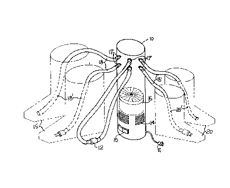
In drawings which illustrate embodiments of the
inventive idea, Figure 1 is a view in perspective showing
the stand up version of the dryer in conjunction with two
pairs of boots.
Figure 2 is a view in perspective showing the wall
mounted version of the said dryer in conjunction with two
pairs of boots.
The drying apparatus illustrated in Figures 1 and 2
comprise a housing 10, having a cylindrical or any other
ergonomical shape and is preferably a rigid injection-
molded plastic product as polypropylene, ABS, or other
suitable material.
The housing 10 is provided with air inlets 14, a three
position switch 15, for LOW-OFF-HI fan speed, and a line
cord 11.
The housing 10 is carrying at one end an electrical
motorized fan 16, which creates an air pressure inside
the said housing.
At the other end the housing includes at least four
fitting like discharge ports 17.
Flexible tubings 18, made of suitable flexible material
such as a 10 mm (3/8") inside diameter commercial vinyl,
are removably clamped onto ports 17.
Dotted lines 18' indicate the respective tubing portions
within boots 19, 20 and each tube will be understood to
have an open end for discharge the air flow toward but at
some clearance from the toe end of the boot in which it
is inserted.
Half of the tubings 18 have removably attached plastic
connectors 12. The said tubings not used are connected in
pairs via connectors 12 to save the air flow.
In the embodiment shown in Figure 2 the housing 10 is
supported by the holding clamps 21 in the wall mounted
version, but otherwise, the construction may be the same
as that described above.
As many changes can be made to the disclosure herein
without departing from the scope of the invention, it is
intended that all material contained herein be
interpreted as illustrative, and this invention to be
limited only by the appending claims.

Representative Drawing
A single figure which represents the drawing illustrating the invention.
Administrative Status

2024-08-01:As part of the Next Generation Patents (NGP) transition, the Canadian Patents Database (CPD) now contains a more detailed Event History, which replicates the Event Log of our new back-office solution.

Please note that "Inactive:" events refers to events no longer in use in our new back-office solution.

For a clearer understanding of the status of the application/patent presented on this page, the site Disclaimer , as well as the definitions for Patent , Event History , Maintenance Fee  and Payment History  should be consulted.

Event History

Description Date
Time Limit for Reversal Expired 2003-08-25
Letter Sent 2002-08-26
Grant by Issuance 1999-03-30
Inactive: Final fee received 1998-08-19
Pre-grant 1998-08-19
Inactive: Received pages at allowance 1998-08-12
Inactive: Office letter 1998-07-30
Notice of Allowance is Issued 1998-07-29
Letter Sent 1998-07-29
Notice of Allowance is Issued 1998-07-29
Inactive: Status info is complete as of Log entry date 1998-07-20
Inactive: Application prosecuted on TS as of Log entry date 1998-07-20
Inactive: IPC removed 1998-05-09
Inactive: IPC assigned 1998-05-09
Inactive: IPC removed 1998-05-09
Inactive: First IPC assigned 1998-05-09
Inactive: IPC assigned 1998-05-09
Inactive: Approved for allowance (AFA) 1998-05-06
Inactive: Inventor deleted 1997-08-26
Application Published (Open to Public Inspection) 1996-02-26
Request for Examination Requirements Determined Compliant 1994-10-19
All Requirements for Examination Determined Compliant 1994-10-19

Abandonment History

There is no abandonment history.

Maintenance Fee

The last payment was received on 1998-08-19

Note : If the full payment has not been received on or before the date indicated, a further fee may be required which may be one of the following

  • the reinstatement fee;
  • the late payment fee; or
  • additional fee to reverse deemed expiry.

Patent fees are adjusted on the 1st of January every year. The amounts above are the current amounts if received by December 31 of the current year.
Please refer to the CIPO Patent Fees web page to see all current fee amounts.

Fee History

Fee Type Anniversary Year Due Date Paid Date
MF (application, 3rd anniv.) - small 03 1997-08-25 1997-08-21
Final fee - small 1998-08-19
MF (application, 4th anniv.) - small 04 1998-08-25 1998-08-19
MF (patent, 5th anniv.) - small 1999-08-25 1999-07-16
MF (patent, 6th anniv.) - small 2000-08-25 2000-07-11
MF (patent, 7th anniv.) - small 2001-08-27 2001-08-23
Owners on Record

Note: Records showing the ownership history in alphabetical order.

Current Owners on Record
ANCA DAN-CONSTANTIN
Past Owners on Record
None
Past Owners that do not appear in the "Owners on Record" listing will appear in other documentation within the application.
Documents

To view selected files, please enter reCAPTCHA code :


To view images, click a link in the Document Description column (Temporarily unavailable). To download the documents, select one or more checkboxes in the first column and then click the "Download Selected in PDF format (Zip Archive)" or the "Download Selected as Single PDF" button.

List of published and non-published patent-specific documents on the CPD .

If you have any difficulty accessing content, you can call the Client Service Centre at 1-866-997-1936 or send them an e-mail at CIPO Client Service Centre.

({010=All Documents, 020=As Filed, 030=As Open to Public Inspection, 040=At Issuance, 050=Examination, 060=Incoming Correspondence, 070=Miscellaneous, 080=Outgoing Correspondence, 090=Payment})


Document
Description 
Date
(yyyy-mm-dd) 
Number of pages   Size of Image (KB) 
Representative drawing 1997-12-07 1 18
Description 1998-08-11 2 97
Claims 1996-02-25 1 35
Description 1996-02-25 2 101
Abstract 1996-02-25 1 9
Drawings 1996-02-25 1 35
Description 1998-04-21 2 92
Claims 1998-04-21 2 83
Representative drawing 1999-03-23 1 13
Commissioner's Notice - Application Found Allowable 1998-07-28 1 166
Maintenance Fee Notice 2002-09-22 1 177
Correspondence 1998-07-28 1 96
Correspondence 1998-08-11 2 79
Correspondence 1998-08-18 1 32
Fees 2001-08-02 1 118
Fees 1998-08-18 1 32
Correspondence 1998-01-19 1 6
Fees 1997-08-20 1 85
Fees 1999-07-15 1 118
Fees 2000-07-10 1 128
Fees 1996-04-11 1 40
Prosecution correspondence 1994-08-24 3 114
Prosecution correspondence 1997-11-17 5 225
Examiner Requisition 1997-06-12 2 66
Courtesy - Office Letter 1998-01-19 1 14
Courtesy - Office Letter 1995-07-25 1 30
Correspondence related to formalities 1994-10-18 1 25