Language selection

Search

Patent 2131043 Summary

Third-party information liability

Some of the information on this Web page has been provided by external sources. The Government of Canada is not responsible for the accuracy, reliability or currency of the information supplied by external sources. Users wishing to rely upon this information should consult directly with the source of the information. Content provided by external sources is not subject to official languages, privacy and accessibility requirements.

Claims and Abstract availability

Any discrepancies in the text and image of the Claims and Abstract are due to differing posting times. Text of the Claims and Abstract are posted:

  • At the time the application is open to public inspection;
  • At the time of issue of the patent (grant).
(12) Patent Application: (11) CA 2131043
(54) English Title: GAS-FILLED LIGHTNING ARRESTER HAVING COPPER ELECTRODES
(54) French Title: PARAFOUDRE A ISOLATION GAZEUSE MUNI D'ELECTRODES DE CUIVRE
Status: Deemed Abandoned and Beyond the Period of Reinstatement - Pending Response to Notice of Disregarded Communication
Bibliographic Data
(51) International Patent Classification (IPC):
  • H01T 04/10 (2006.01)
  • H01T 04/02 (2006.01)
  • H01T 04/12 (2006.01)
(72) Inventors :
  • LANGE, GERHARD (Germany)
(73) Owners :
  • EPCOS AG
  • SIEMENS AKTIENGESELLSCHAFT
(71) Applicants :
  • EPCOS AG (Germany)
  • SIEMENS AKTIENGESELLSCHAFT (Germany)
(74) Agent: SMART & BIGGAR LP
(74) Associate agent:
(45) Issued:
(22) Filed Date: 1994-08-29
(41) Open to Public Inspection: 1995-03-01
Examination requested: 2001-04-11
Availability of licence: N/A
Dedicated to the Public: N/A
(25) Language of filing: English

Patent Cooperation Treaty (PCT): No

(30) Application Priority Data:
Application No. Country/Territory Date
P 43 30 178.9 (Germany) 1993-08-31

Abstracts

English Abstract


Abstract of the Disclosure
To achieve a contact with copper electrodes that discharges axially to a
slight degree and is especially favorable a manufacturing standpoint, a gas-filled
arrester with a ceramic insulator and copper electrodes is provided having a
contact ring which is soldered endwise on an edge of each bowl-shaped copper
electrode. The height (h) of the ring is greater than the thickness (D) of the
edge of the copper electrode. The contact ring is made of iron or a magnetic,
stainless alloy with a coefficient of thermal expansion .alpha. = 120 x 10-7/°C.


Claims

Note: Claims are shown in the official language in which they were submitted.

-6-
What is claimed is:
1. A gas-filled lightning arrester comprising:
two tubular ceramic insulators;
two bowl-shaped copper electrodes, each soldered by their edges endwise
on an end of one of said tubular ceramic insulators, where each edge of said
electrodes has a wall thickness of less than 0.6 mm;
a contact ring coupled endwise to each of said copper electrodes and
made of a material capable of being welded and having a coefficient of thermal
expansion of approximately 120 x 10-7/°C, said contact ring having a height (h)
greater than a wall thickness (D) of each of said edges of said copper electrodes,
where each contact ring is soldered to one of said edges of said copper
electrodes; and
a connecting wire welded to an outside surface of each of said contact
rings.
2. The lightning arrester of claim 1, wherein said contact ring is made
of nickel.
3. The lightning arrester of claim 1, wherein said contact ring is made
of iron.
4. The lightning arrester of claim 1, wherein said contact ring is made
of iron alloy.
5. The lightning arrester of claim 1, wherein said contact ring is made
of a round wire.
6. The lightning arrester of claim 1, wherein said contact ring is made
of a shaped wire having a substantially circular cross section and a flattened
surface in a vicinity of a contact surface, where the copper electrode is also

-7-
flattened at an outer jacket surface and tapered domewise at an inner jacket
surface.
7. The lightning arrester of claim 1, wherein the contact ring comprises
a stamped part with an approximately rectangular cross section.
8. The lightning arrester of claim 7, wherein a cross section of said
contact ring has a flat conical taper at an inner jacket surface.
9. The lightning arrester of claim 1, wherein said height (h) of the
contact ring is between 0.8 and 1 mm.
10. The lightning arrester of claim 1, wherein said contact ring has a
galvanically applied silver layer having a thickness of approximately 5 microns.
Description

Note: Descriptions are shown in the official language in which they were submitted.


~ 3
Gas-Filled Lightning Arrester lEIaving Copper Electrodes
Bacl;Qround of Invention
The present invention relates to electrical components, and more
particularl~t the structural design of the connections of lightning arresters having
bo~ l-shaped electrodes which are soldered to a tubular ceramic insulator.
In gas-filled lightning arresters having bowl-shaped copper electrodes, the
use of copper as the electrode material offers the advantages of small (limensions ~ -
and high current carrying capacity. The electrodes can be manufactured by an
extrusion or embossing method. Because of the considerable differences in
10 coefficients of thermal e:cpansion of copper and ceramic, the electrodes have a
wall thickness of less than 0.6 mm in the vicinity of the soldered connections
with the ceramic insulator. Thermal stresses can therefore be compensated by
the plastic deformability of the copper. Connection of copper electrodes in the
a~cial direction is either performed positively by the edge provided for soldering
15 with the cerarnic insulator or integrally by connecting wires welded to a stub in
the rear bottom area of the electrode surface itself (as seen in U.S. Patent
4,266,260, U.S. Patent 4~433,354). Connecting wires soldered in this way can
also be bent radially (as seen in U.S. Patent 4,866,563). Radial connection of

connecting wires requires a certain amount of space in the axial direction that is
not always available when lightning arresters are mounted in electronic
equipment. In these cases, axial contacts cannot be used. This type of electrodecontact likewise cannot be used when the electrodes are fitted axially with an
5 auxiliary device such as an overload protector. In these cases the electrodes can
be provided with radially welded connecting wires, provided the electrode edge
hais sufficient wall thickness, as is usual in electrodes made of an iron alloy
otherwise conventionally used for this purpose (see U.S. Patent 4,984,125).
As shown in German Patent Application No. P 43 18 366.2, a terminal is
connected integrally, endwise with the soldering edge of a copper electrode; theterminal has the shape of a ring in this area. The ring and the radially
projecting connecting wire are made integral. The ring simultaneously serves to
center an additional cylindrical component.
1 5
In a gas-filled lightning arrester having two bowl-shaped copper
electrodes soldered by their edges endwise on a tubular cerarnic insulator, there
is a need for a contact on the copper electrode that discharges axially to the
smallest degree possible and can be readily manufactured.
'O
Summary of the Invention
This and other needs are met by the lightning arrester of the present
invention. The edge of each copper electrode is provided endwise with a
contact ring made of a weldable material having a coefficient of thermal
25 expansion of approximately 120 x lO-'/C. The contact ring hasa height greater
than the wall thickness of the copper electrode, and the contact ring is soldered
to the edge of the copper electrode. Also, a connecting wire is welded to the
outer jacket surface of the contact ring.
With such a design of the lightning arrester, a radial contact is provided
axially in a very limited space by connecting wires that are soldered tangentially
or radially. The use of a contact ring with a coefficient of thermal expansion of

approximately 120 x 10 7/C results in a reduction of the shear stress on the
soldered connection between the copper electrode and the cerarnic part because
the coefficient of thermal expansion of the contact ring is between the
coefficients of thermal expansion of ceramic ~i.e., 75 x lo 7/oC) and copper (i.e.,
approximately 170 x 107/C) and thus partially takes up the shrinkage stresses
of the copper electrode in the marginal area. Consequently, alloys containing
iron are preferred for the contact ring, however pure nickel can also be used.
Reduction of shear stress in the area of the soldered connection between the
copper electrode and ceramic insulator results in a higher electrical and, hence,
thermal loading capacity of the lightning arrester. A connecting wire is welded
to a special contact ring initially in the course of the manufacturing process of
the lightning arrester. The use of this special contact ring offers advaintages
from a manufacturing standpoint in that only lightning arresters provided with
contact rings can be subjected to manufacturing processes such as drum
I ~ grinding, pickling. silverplating or tinplating, printing, and shaping without
interference from existing wire connections. Silver is advantageously used for
~ soldering the contact ring to the edge of the copper electrode. The silver is
? applied lo the contact ring galvanically with a layer thickness of about S
,!j microns. At the soldering temperature of the lightning arrester, this silver layer
~0 forms a soldered connéction with the surface layer of the edge of the copper
electrode in the vicinity of the eutectic point. In this manner, it is assured that -
soldering of the contact ring and the copper electrode can be performed
simultaneously with the soldering of the copper electrode and the ceramic
insulator.
; The contact ring of the present invention can be made from a round wire.
- A shaped wire can also be used having a cross section, which differs from a
circular shape~ that is flattened in the area of contact with the copper electrode,
and is also flattened on the outer jacket surface, and is tapered in a dome shape
at the inner jacket surface. Large connecting areas are available in the area ofthe integral connection, while the dome-shaped taper can serve to center an , ~ -
additional component. It is advantageous, if the contact ring is made of a
.,; ''
':
. . .

-4-
starnped preform with an approximately rectangular cross section. By drum
grinding, therefore, chamfers can be forrned in the edges of the ring that ensure
that a welded seam is formed that is not applied radially in the area of the
contact surface with the edge of the copper electrode. A stamped contact ring
5 can also be designed so that its cross section has a flat conical taper on the inner
surface.
With the connecting wires welded onto a gas-filled lightning arrester,
having a wire diameter of I mm, the height of the contact ring is
10 advarltageously about 0.8 to I mm. Material for the contact ring can be
magnetic, stainless steels having a coefficient of thermal expansion of
approximately 120 x 107/C, in particular, a steel of type X8Crl7 or alloy N42,
as well as the mater.al known as Vacon conventionally used for vacuum
purposes (which is made of a cobalt-nickel-steel alloy).
1~ .
Brief Description of the Drawin~s
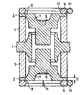
Fig. 1 is a cross-sectional diagram of a three-electrode lightning arrester
having contact rings mounted on the end electrodes, where the rings are made of
a shaped wire, and a welded connecting wire;
'O
Fig. 2 is a cross-sectional diagram of a contact ring made of a round
wire having a connecting wire welded thereon; and
Figs. 3 and 4 are cross-sectional diagrams of stamped contact rings
25 having welded connecting wires.
Detailed Description
Referring to Fig. 1, a cross-section of a gas-filled three-electrode
lightning arrester is shown having a central electrode 1, two end electrodes 2
30 and 3, and tubular ceramic insulators 4 and 5. Each of the two end electrodes 2
and 3 is bowl-shaped and has a thick bottom 6, a side wall 7, and a thin rim or
edge 8. Edge 8 hdS a wall thickness of about 0.5 mm. The twl) end electrodes
I

2 and 3 are soldered endwise by their edges 8 to cerarnic insulators 4 and 5, ;
respectively. Electrodes 2 and 3 arc made of copper and are produced by
extrusion in a known manner. ~ ;
.
A contact ring 9 comprising a magnetic stainless iron alloy with a
coefficient of thermal expansion of about 120 x 10-7/C is soldered on the edge
8 of each electrode 2 or 3. Each contact ring 9 has a silver coating 10, which
melts during the soldering process and forms a silver-copper alloy with the
superficial copper layer at edge 8. The height, h, of each contact ring is greater
than the wall thickness, D, of the edge 8 and is about 0.8 to I mm. A
connecting wire 11 is welded tangentially to the contact ring 9. The connecting
wire 11 is made of copper and is tinned or silvered. The contact rings 9 are
each made of a shaped wire formed into a ring. The shape of this wire is
chosen so that the contact surface with the edge 8 and the outer jacket surface
are made essentially flat, while the inner jacket surface is tapered like a dome.
Referring to Fig. 2. the contact ring can be made of a round wire 12. As
seen in Fig. 3, the contact ring 13 can be made of a stamped part with a flat
design for the contact surface, the covering surface, and the outer jacket surface.
~0 The inner jacket surface has a flat conical taper 15. As seen in Fig. 4, thecontact ring 14 can be made of a stamped part with a rectangular cross section,
with chamfers 16 formed at the edges by drum grinding. With the gas-filled
lightning arrester of the present invention, a contact on the copper electrode : I
discharges axially to the smallest degree possible and can be readily
manu~actured.
~- ~

Representative Drawing
A single figure which represents the drawing illustrating the invention.
Administrative Status

2024-08-01:As part of the Next Generation Patents (NGP) transition, the Canadian Patents Database (CPD) now contains a more detailed Event History, which replicates the Event Log of our new back-office solution.

Please note that "Inactive:" events refers to events no longer in use in our new back-office solution.

For a clearer understanding of the status of the application/patent presented on this page, the site Disclaimer , as well as the definitions for Patent , Event History , Maintenance Fee  and Payment History  should be consulted.

Event History

Description Date
Inactive: IPC from MCD 2006-03-11
Application Not Reinstated by Deadline 2004-08-30
Time Limit for Reversal Expired 2004-08-30
Deemed Abandoned - Failure to Respond to Maintenance Fee Notice 2003-08-29
Letter Sent 2001-07-10
Amendment Received - Voluntary Amendment 2001-06-26
Letter Sent 2001-05-15
Inactive: Status info is complete as of Log entry date 2001-05-15
Inactive: Application prosecuted on TS as of Log entry date 2001-05-15
Request for Examination Requirements Determined Compliant 2001-04-11
All Requirements for Examination Determined Compliant 2001-04-11
Application Published (Open to Public Inspection) 1995-03-01

Abandonment History

Abandonment Date Reason Reinstatement Date
2003-08-29

Maintenance Fee

The last payment was received on 2002-08-06

Note : If the full payment has not been received on or before the date indicated, a further fee may be required which may be one of the following

  • the reinstatement fee;
  • the late payment fee; or
  • additional fee to reverse deemed expiry.

Patent fees are adjusted on the 1st of January every year. The amounts above are the current amounts if received by December 31 of the current year.
Please refer to the CIPO Patent Fees web page to see all current fee amounts.

Fee History

Fee Type Anniversary Year Due Date Paid Date
MF (application, 3rd anniv.) - standard 03 1997-08-29 1997-07-15
MF (application, 4th anniv.) - standard 04 1998-08-31 1998-07-23
MF (application, 5th anniv.) - standard 05 1999-08-30 1999-07-23
MF (application, 6th anniv.) - standard 06 2000-08-29 2000-07-26
Request for examination - standard 2001-04-11
Registration of a document 2001-05-31
MF (application, 7th anniv.) - standard 07 2001-08-29 2001-08-03
MF (application, 8th anniv.) - standard 08 2002-08-29 2002-08-06
Owners on Record

Note: Records showing the ownership history in alphabetical order.

Current Owners on Record
EPCOS AG
SIEMENS AKTIENGESELLSCHAFT
Past Owners on Record
GERHARD LANGE
Past Owners that do not appear in the "Owners on Record" listing will appear in other documentation within the application.
Documents

To view selected files, please enter reCAPTCHA code :


To view images, click a link in the Document Description column. To download the documents, select one or more checkboxes in the first column and then click the "Download Selected in PDF format (Zip Archive)" or the "Download Selected as Single PDF" button.

List of published and non-published patent-specific documents on the CPD .

If you have any difficulty accessing content, you can call the Client Service Centre at 1-866-997-1936 or send them an e-mail at CIPO Client Service Centre.


Document
Description 
Date
(yyyy-mm-dd) 
Number of pages   Size of Image (KB) 
Representative drawing 1999-10-24 1 16
Drawings 1995-05-12 1 66
Claims 1995-05-12 2 84
Abstract 1995-05-12 1 31
Description 1995-05-12 5 286
Reminder - Request for Examination 2001-04-30 1 117
Acknowledgement of Request for Examination 2001-05-14 1 178
Courtesy - Abandonment Letter (Maintenance Fee) 2003-10-26 1 176
Correspondence 2001-06-10 1 20
Fees 1996-07-22 1 79