Language selection

Search

Patent 2131066 Summary

Third-party information liability

Some of the information on this Web page has been provided by external sources. The Government of Canada is not responsible for the accuracy, reliability or currency of the information supplied by external sources. Users wishing to rely upon this information should consult directly with the source of the information. Content provided by external sources is not subject to official languages, privacy and accessibility requirements.

Claims and Abstract availability

Any discrepancies in the text and image of the Claims and Abstract are due to differing posting times. Text of the Claims and Abstract are posted:

  • At the time the application is open to public inspection;
  • At the time of issue of the patent (grant).
(12) Patent: (11) CA 2131066
(54) English Title: DEBARKER ARMS AND DEBARKER TIPS FOR MOUNTING ON LOG BARKING MACHINES
(54) French Title: BRAS ET EXTREMITES DU DISPOSITIF D'ECORCAGE D'UNE ECORCEUSE
Status: Term Expired - Post Grant Beyond Limit
Bibliographic Data
(51) International Patent Classification (IPC):
  • B27L 1/00 (2006.01)
  • B23B 27/16 (2006.01)
  • B27G 3/00 (2006.01)
  • B27L 1/08 (2006.01)
  • B27L 3/00 (2006.01)
(72) Inventors :
  • JOHNSON, DENIS (Canada)
  • JOHNSON, YVON (Canada)
(73) Owners :
  • JOHNSON ENTERPRISES INC.
(71) Applicants :
  • JOHNSON ENTERPRISES INC. (Canada)
(74) Agent: NORTON ROSE FULBRIGHT CANADA LLP/S.E.N.C.R.L., S.R.L.
(74) Associate agent:
(45) Issued: 2001-01-30
(22) Filed Date: 1994-08-29
(41) Open to Public Inspection: 1996-03-01
Examination requested: 1999-08-09
Availability of licence: N/A
Dedicated to the Public: N/A
(25) Language of filing: English

Patent Cooperation Treaty (PCT): No

(30) Application Priority Data: None

Abstracts

English Abstract

A debarker arm for a debarking machine, comprised of a crescent shaped member, a debarker arm support, an outwardly forwardly extending flange, a debarker tip receptacle, and a debarker tip seated in said receptacle, the invention comprising said outwardly forwardly extending flange extending above and forwardly of said debarker tip in the direction of incoming logs.


French Abstract

Bras d'écorçage pour écorceuse, composé d'un organe en forme de croissant, d'un support de bras d'écorçage, d'une bride en extension vers l'avant et vers l'extérieur, d'un réceptacle de pointe d'écorçage, et d'une pointe d'écorçage siégeant dans ledit réceptacle, l'invention comprenant ladite bride en extension vers l'avant et vers l'extérieur s'étendant au-dessus et vers l'avant de ladite pointe d'écorçage dans la direction de bûches entrantes.

Claims

Note: Claims are shown in the official language in which they were submitted.

CLAIMS
1. A debarker arm for mounting in a rotor of a debarking machine, the rotor
and debarking arm having a log entry side and log exit side, the debarker arm
comprised of an integral debarker arm support, a debarker arm body, debarker
tip
receptacle, and a debarker receptacle lip, characterized in that the debarker
arm
receptacle is comprised of a receptacle located behind the receptacle lip on
the log
entry side of the debarker arm receptacle, the lip extending substantially to
the end
of the debarker arm receptacle.
2. The debarker arm of claim 1 in which the debarker tip receptacle is
located below the upper surface of the body of the debarker arm.
3. The debarker arm of claim 2 in which the debarker tip receptacle is
comprised of a base, a recess and a threaded aperture defining an annular
threaded
opening and a lip, the annular threaded opening in the receptacle is located
on the
vertical axis of the recess.
4. A debarker tip for mounting on a debarker arm, for mounting in a rotor of a
debarking machine, the rotor, debarking arm and debarker tip having a log
entry side
and a log exit side, the debarker tip having a log engaging side, the debarker
tip
being comprised of an integral base and body, the body having a central
recess. four
chamfered edges and four cutting edges, a threaded aperture defining an
opening
through the interior recess and base of the debarker tip, the threaded opening
located on the vertical axis of the body and base of the debarker tip.

5. The debarker tip of claim 4 in which the interior angle of the cutting
edges
of the debarker tip is at least 30 degrees.
6. The debarker tip of claim 5 in which the interior surfaces of the cutting
edges are metal hardened.
7. The debarker tip of claim 6 in which the cutting edges of the debarker tip
are sharp.
8. The debarker tip of claim 5 in which the debarker tip is machined from a
single piece of steel.
9. A debarker arm for mounting in a rotor of a debarking machine, the rotor
and debarking arm having a log entry side and a log exit side, the debarker
arm
comprised of an integral debarker arm support, a debarker arm body, debarker
tip
receptacle, debarker receptacle lip, and a replaceable debarker tip,
characterized in
that the debarker receptacle lip extends substantially to the end of the
debarker arm
receptacle.
10. The debarker arm and debarker tip of claim 9 in which the debarker tip is
comprised of an integral base and body, the body having a central recess, four
chamfered sides and four cutting edges and means to fasten the debarker tip to
the
debarker arm receptacle.
11. The debarker arm and debarker tip of claim 10 in which the debarker tip
may be unfastened, rotated in the debarker tip receptacle, and refastened to
provide
a fresh active cutting edge for debarking.
12. The debarker arm and debarker tip of claim 11 in which the end of the
debarker receptacle lip is slightly lower than the active cutting edge of the
debarker.

13. A debarker tip receptacle forming the end of a debarker arm for receiving
a debarker tip comprising a recess, a threaded annular opening and at least
one
upstanding lip, the improvement comprising an upstanding lip on at least one
side of
the debarker tip receptacle to control the depth of cut of the debarker tip.
14. The debarker tip receptacle of claim 13 comprised of a recess having a
flat bottom and inclined side walls, the lip or lips comprising an upward
extension of
said inclined side walls, said inclined side walls and lips supporting the
debarker tip
against movement when the debarker tip is fastened in the debarker tip
receptacle.
15. A debarker tip for mounting on a debarker arm, the debarker tip being
comprised of an integral base, body and cutting tips, the base having a
plurality of
sides and a flat bottom extends downwardly from the body, the body is wider
than
the base, the sides of the body are outwardly inclined, the central top of the
base is
flat with a central threaded aperture defining an opening through the central
axis of
the base and body, the cutting tips extending upwardly and outwardly from the
top
flat portion of the base, the cutting tips extending upwardly and outwardly
from the
base, the interior angle at the base of the cutting tips being at least
150° relative to
the top central flat portion of the base, the corners of the cutting tips are
chamfered.

Description

Note: Descriptions are shown in the official language in which they were submitted.


2131066
DEB~RK~,R ARMS AND DEBARKER TIPS
FOR MOUNTING ON LOG BARKING MACHINES
This invention relates to debarker arms and debarker tips for
mounting on the end of the debarker arms. The debarker arms with
debarker tips are for mounting on barking m~(~hines of the type having a
number of arms mounted in an annular rotating member and pressed
radially inwardly into contact with a log being fed axially therethrough to
remove the bark from logs.
The debarker arms of the current invention have fastening means at
their inner end to fasten the debarker arm to the inside of the annular
rotating member. The outer end of the debarker arm has a receptacle for
receiving and ret~ining a debarker tip. The debarker arms of this invention
are fabricated from high strength alloy steel. The debarker unit has a flange
extending towards the log entrance end of the annular rotating member, the
flange is located above and extends in front of the debarker tip to protect the
edge of the log freeing the entering log from damage by the ends of incoming
logs. A lip on the log entry side of the debarking arm immediately in front of
the debarker tip receptacle also protects the debarker tip facing the
incoming log from excessive damage from the incoming log.
The debarker tips of the present invention have a plurality of
debarking edges. Only one edge engages the log at any time for the purpose
of debarking the log. When the log engaging edge of a tip is worn the
debarking tip is unfastened or loosened sufficiently to rotate the debarking
tip in the debarking arm receptacle to locate a fresh log engaging edge of the
debarker tip and the debarker tip is firmly fastened in the debarker arm
receptacle. The procedure of unfastening or loosening the debarker tip is

21~1066
- 2 -
followed each time the log engaging edge of the debarker tip becomes dull or
is damaged. The debarker tip is rotated through ninety degrees if a four
edged debarking tip is used and a fresh sharp unused surface of the
debarker tip is located in the log engaging position.
Background of the Invention
Debarker tips having four scraping surfaces are in use but such
debarking tips can only be used on three sides as the side which first faces
the log coming axially through the arms encounters the end of the log and is
10 frequently damaged such that the first surface of the debarker unit to face
the incoming log is not later available for use in debarking.
Existing debarking tips which are in use have relatively thin and
relatively dull surfaces which are often damaged by the frozen bark
encountered in debarking logs in northern climates in the winter. The
15 relatively dull surfaces of existing debarking tips when used on frozen logs
result in some breakage of debarker arms currently in use.
Sllmm~ry of the Invention
In the instant invention the debarking tips which are mounted on the
20 free end of the debarking arm are protected by a lip on the log entry side ofthe debarker arm below the top of the debarker tip. The lip on the log-entry
side of the debarking arm protects the debarker tip facing the incoming log.
Protecting the edge of the debarker tip facing the incoming log makes that
edge of the debarker tip available for later debarking when the debarker tip
25 is rotated into log engaging position.
The end of the lip extending upwardly from the side of the recess in
which the debarker tip is mounted also serves to prevent the log engaging
edge of the debarker tip from cutting too deeply into the wood of the log

2131066
being debarked. The sharp edge of the log-engaging edge of the debarker tip
is designed to run between the bark and the wood of the log. The end of the
lip extending along the log-entry side of the log extends to a position below
one edge of the log engaging edge of the debarker tip preventing the tip from
digging too deeply into the wood of the log.
The debarker tips of the invention have edges with the general cross-
sectional shape of an isosceles tri~ngle with a substantial base. A wear
resistant coating is applied to the inside edge of the debarker tips. The
debarker tips are sharp which increases their effectiveness in deb~rking
frozen logs during the winter.
A flange on the log entry side of the debarker arm extends forwardly
of the mounted debarker tip. The flange on the log entry side of the
debarker arm also extends above the back edge of the mounted debarker tip.
When a new log enters axially through the annular rotating member in
which the debarker arms are mounted, the front of the log will strike the
forward edge of the flange of the debarker arm as opposed to the edge of the
debarker tip facing the entering log. The lip on the log entry side of the
debarker tip referred to above also serves to protect the edge of the debarker
tip on the log entry side from engaging the entering log.
The debarker arms of the instant invention are manufactured from
alloy steel. The alloy steel debarker arms are less susceptible to damage
than debarker arms which are cast.
One embodiment of the invention relates to a debarker arm for a
debarking m~hine, comprised of a crescent shaped member, a debarker arm
support, an outwardly forwardly extending flange, a debarker tip receptacle,
and a debarker tip seated in said receptacle, the invention comprising said
outwardly forwardly extending flange extending above and forwardly of said
debarker tip in the direction of incoming logs.

2131066
- 4 -
In another embodiment the invention relates to a debarker arm for a
debarking m~hine, comprised of a crescent shaped member, a debarker arm
support, an outwardly forwardly extending flange and a debarker tip
receptacle, the invention comprising said outwardly forwardly extending
5 flange extending above and forwardly of said debarker tip receptacle in the
direction of incoming logs.
In still another embodiment the invention relates to a debarker tip for
mounting on a debarker arm, the debarker tip being comprised of an
integral base, body and cutting tips, the base extending downwardly from
10 the body and the cutting tips extending upwardly from each side of the body,
the cutting edges increasing in thickness from the exterior cutting surface to
the body.
Brief Description of the Drawings
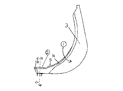
Figure 1 is a view of the debarker arm and debarker tip as seen from
the log entry side of the rotating member in which a plurality of arms are
mounted.
Figure 2 is a view of the debarker arm and log engaging edge of the
debarker tip as seen from the axis of the rotating member in which a
20 plurality of arms are mounted.
Figure 3 is a top view of the debarker arm and debarker tip as viewed
from the top when mounted in the rotating member supporting a plurality of
arms.
Figure 4 is a cross-sectional view of the debarker tip of this invention
25 mounted in the recess at the end of the debarker arm of Figure 1.
Figure 5 is a perspective axonometric view of the end of the debarker
arm and debarker tip as viewed perspectively from the side and rear of the
view in Figure 1.

2131066
- 5 -
Detailed Description of the Pleferred Embodiments
R~f~rring to Figure 1, the debarker arm is indicated by the number 1
and the debarker tip is indicated by the number 2. The debarker arm 1 is
formed of a crescent shaped piece of steel 3. A flange 4 extends outwardly
forwardly on one side along the top of the crescent shaped piece of steel 3.
The outwardly forwardly extending flange 4 commences near the arm
support of the crescent shaped piece of steel 3 and ends immediately before
the debarker tip 2. As seen in Figure 2 the flange 4 increases in width from
10 the top of the debarker arm and is at its widest immediately above the
debarker tip 2. As seen in Figure 2 the bottom portion of the flange 4
extends forwardly of the debarker tip at the base to protect the front edge of
the debarker tip 2 from logs entering the rotating member at a right angle to
the flange 4. As seen in Figure 1 the base 5 of the lower end of flange 4 near
15 the debarker tip 2is higher than the back edge of the debarker tip 2 to
protect the log entry side of debarker tip 2 from being struck by incoming
logs. As seen in Figure 2 the upper end of the crescent shaped steel member
3 has an arm support flange 6 extending horizontally therefrom in the
opposite direction to flange 3. The arm support flange 6 may take other
forms depending on the form of the arm support receptacle of the arm
support receptacle of the rotating member to which the debarker arm 1 is to
be fastened.
As best seen in Figures 1 and 4 a solid piece of steel forming a
debarker tip receptacle 7 is welded to the crescent shaped steel member 3
and flange 4. The debarker tip receptacle 7 includes a recess 8, an annular
opening 9 and an upstanding lip 10. As seen in Figure 4 the annular
opening in the base of the debarker tip receptacle 7 is threaded to receive a
bolt 11 having a threaded portion 12 and a head 13.

2131066
As seen in Figure 4 the debarker tip 2 has a base 14 having an
exterior shape corresponding to the shape of the recess 8 for receipt and
retention in the recess 8. Integral with and extending outwardly upwardly
from the base 14 is the body 24 of the debarker tip 2. The debarker tip 2
has a central threaded annular aperture 15 adapted to receive the threaded
portion 12 of bolt 11.
As seen in Figure 3 the body 24 of debarker tip 2 has four cutting
edges 16,17,18 and 19 and four chamfered edges 20, 21, 22 and 23 located
between the cutting edges 16,17,18 and 19. As seen in Figure 4 the interior
of the top 24 of the debarker tip 2 is centrally recessed. The four cutting
edges 16,17,18 and 19 are triangular in cross section, the width of the
cutting edges 16,17,18 and 19 increases from top to bottom. The interior
angle of the cutting edges is at least 30. The inside of the cutting edges 16,
17,18 and 19 are hardened to maintain the sharp edges of the cutting edges
16,17 18 and 19.
The debarker tips 2 are det~ch~hle from the lower end of the debarker
arm 1 by removal of the bolt 11. It is also possible to loosen the bolt 11 so asto release the base 14 of the debarker tip 2 from the recess 8 of debarker tip
receptacle 7 and turn the debarker tip 2 to present a fresh cutting edge 16,
17,18 or 19 to the log contacting position in which edge 16is shown in
Figures 1 and 3. With a fresh cutting edge 16,17,18 or 19 in position the
base 14 of the debarker tip 2 is lowered into the debarker tip receptacle 7
and the bolt 11 is tightened securing the base 14 in the debarker tip
receptacle.
In operation, the debarker arms 1 and other debarker arms are
mounted in an annular rotating member. The debarker arms 1 are pressed
radially inwardly. The log is fed into the annular rotating member axially.
The end of the log strikes the flange 4 of the debarker arm 1 which extends

2131066
7 -
forwardly and above the debarker tip 2 relative to the incoming log,
protecting the cutting edge of the debarker tip 2 facing the incoming log from
substantial contact with the incoming log. The upstanding lip 10 extends
upwardly on the end of the debarker arm 1 partially covering the side of the
5 cutting edge of the debarker arm facing the incoming log, providing further
protection to the edge of the debarker tip 2 facing the incoming log.
When the end of the log has passed the debarker arm 1 the cutting
edge of the debarker tip 2 engages the bark of the log and begins removing
bark from the log as the annular rotating member supporting the debarker
10 arms rotates about the log which is being fed axially through the annular
rotating member.
The heat treatment of the debarker tips is known in the art and
suitable harllening materials may be applied to the inside edge of the
debarker tip in the conventional manner. It will be apparent to those skilled
15 in the art that variations may be made to the details of the debarker arms
and debarker tips described herein without departing from the invention.

Representative Drawing
A single figure which represents the drawing illustrating the invention.
Administrative Status

2024-08-01:As part of the Next Generation Patents (NGP) transition, the Canadian Patents Database (CPD) now contains a more detailed Event History, which replicates the Event Log of our new back-office solution.

Please note that "Inactive:" events refers to events no longer in use in our new back-office solution.

For a clearer understanding of the status of the application/patent presented on this page, the site Disclaimer , as well as the definitions for Patent , Event History , Maintenance Fee  and Payment History  should be consulted.

Event History

Description Date
Inactive: Expired (new Act pat) 2014-08-29
Inactive: Office letter 2007-08-27
Revocation of Agent Requirements Determined Compliant 2007-08-27
Appointment of Agent Requirements Determined Compliant 2007-08-27
Appointment of Agent Request 2007-07-30
Revocation of Agent Request 2007-07-30
Revocation of Agent Requirements Determined Compliant 2007-04-10
Inactive: Office letter 2007-04-10
Appointment of Agent Requirements Determined Compliant 2007-04-10
Inactive: Office letter 2007-01-29
Revocation of Agent Request 2007-01-29
Appointment of Agent Request 2007-01-29
Inactive: Corrective payment - s.78.6 Act 2007-01-18
Inactive: IPC from MCD 2006-03-11
Inactive: Entity size changed 2002-08-15
Grant by Issuance 2001-01-30
Inactive: Cover page published 2001-01-29
Pre-grant 2000-10-16
Inactive: Final fee received 2000-10-16
Letter Sent 2000-10-02
Notice of Allowance is Issued 2000-10-02
Inactive: Approved for allowance (AFA) 2000-09-14
Letter Sent 2000-03-21
Inactive: Single transfer 2000-02-23
Revocation of Agent Requirements Determined Compliant 1999-10-26
Inactive: Office letter 1999-10-26
Appointment of Agent Requirements Determined Compliant 1999-10-26
Revocation of Agent Request 1999-10-07
Appointment of Agent Request 1999-10-07
Inactive: Status info is complete as of Log entry date 1999-08-13
Letter Sent 1999-08-13
Inactive: Application prosecuted on TS as of Log entry date 1999-08-13
All Requirements for Examination Determined Compliant 1999-08-09
Request for Examination Requirements Determined Compliant 1999-08-09
Application Published (Open to Public Inspection) 1996-03-01

Abandonment History

There is no abandonment history.

Maintenance Fee

The last payment was received on 2000-03-31

Note : If the full payment has not been received on or before the date indicated, a further fee may be required which may be one of the following

  • the reinstatement fee;
  • the late payment fee; or
  • additional fee to reverse deemed expiry.

Please refer to the CIPO Patent Fees web page to see all current fee amounts.

Owners on Record

Note: Records showing the ownership history in alphabetical order.

Current Owners on Record
JOHNSON ENTERPRISES INC.
Past Owners on Record
DENIS JOHNSON
YVON JOHNSON
Past Owners that do not appear in the "Owners on Record" listing will appear in other documentation within the application.
Documents

To view selected files, please enter reCAPTCHA code :


To view images, click a link in the Document Description column. To download the documents, select one or more checkboxes in the first column and then click the "Download Selected in PDF format (Zip Archive)" or the "Download Selected as Single PDF" button.

List of published and non-published patent-specific documents on the CPD .

If you have any difficulty accessing content, you can call the Client Service Centre at 1-866-997-1936 or send them an e-mail at CIPO Client Service Centre.


Document
Description 
Date
(yyyy-mm-dd) 
Number of pages   Size of Image (KB) 
Abstract 1996-03-01 1 12
Cover Page 1996-04-22 1 16
Description 1996-03-01 7 306
Claims 1996-03-01 2 45
Drawings 1996-03-01 2 44
Claims 1999-08-27 3 108
Cover Page 2001-01-04 1 26
Representative drawing 1998-02-18 1 4
Representative drawing 2001-01-04 1 4
Acknowledgement of Request for Examination 1999-08-13 1 193
Courtesy - Certificate of registration (related document(s)) 2000-03-21 1 113
Commissioner's Notice - Application Found Allowable 2000-10-02 1 163
Correspondence 1999-10-07 2 75
Correspondence 1999-10-26 1 9
Correspondence 1999-10-26 1 8
Correspondence 2000-10-16 1 51
Fees 1997-07-16 1 48
Fees 1998-08-21 1 44
Fees 1999-06-29 1 46
Correspondence 2007-01-29 1 15
Correspondence 2007-01-29 1 38
Correspondence 2007-04-10 1 13
Correspondence 2007-04-10 1 15
Correspondence 2007-07-30 2 69
Correspondence 2007-08-27 1 13
Correspondence 2007-08-27 1 16
Fees 1996-07-29 1 48