Language selection

Search

Patent 2131254 Summary

Third-party information liability

Some of the information on this Web page has been provided by external sources. The Government of Canada is not responsible for the accuracy, reliability or currency of the information supplied by external sources. Users wishing to rely upon this information should consult directly with the source of the information. Content provided by external sources is not subject to official languages, privacy and accessibility requirements.

Claims and Abstract availability

Any discrepancies in the text and image of the Claims and Abstract are due to differing posting times. Text of the Claims and Abstract are posted:

  • At the time the application is open to public inspection;
  • At the time of issue of the patent (grant).
(12) Patent Application: (11) CA 2131254
(54) English Title: PISTON HAVING A LINER AND METHOD FOR MANUFACTURING SAME
(54) French Title: PISTON AVEC CHEMISAGE ET METHODE DE FABRICATION CONNEXE
Status: Deemed Abandoned and Beyond the Period of Reinstatement - Pending Response to Notice of Disregarded Communication
Bibliographic Data
(51) International Patent Classification (IPC):
  • F16J 01/00 (2006.01)
  • B22D 15/02 (2006.01)
  • B22D 19/00 (2006.01)
(72) Inventors :
  • GORSKY, JOHN LAWRENCE (United States of America)
  • HUDY, WILLIAM (United States of America)
(73) Owners :
  • FORD MOTOR COMPANY OF CANADA, LIMITED
(71) Applicants :
  • FORD MOTOR COMPANY OF CANADA, LIMITED (Canada)
(74) Agent: MARKS & CLERK
(74) Associate agent:
(45) Issued:
(22) Filed Date: 1994-08-31
(41) Open to Public Inspection: 1995-03-08
Examination requested: 2001-02-28
Availability of licence: N/A
Dedicated to the Public: N/A
(25) Language of filing: English

Patent Cooperation Treaty (PCT): No

(30) Application Priority Data:
Application No. Country/Territory Date
08/116,833 (United States of America) 1993-09-07

Abstracts

English Abstract


-14-
Abstract
A piston assembly (10) for use in an engine.
The piston assembly (10) includes a piston body (12)
with a liner (24) covering the interior surface (22)
thereof. The liner (24) imbues added strength and
dimensional stability during casting, machining, en-
gine assembly, and in service. At the same time,
piston weight for a given volume is reduced without
sacrificing strength. The invention also includes a
method for manufacturing the piston assembly (10).


Claims

Note: Claims are shown in the official language in which they were submitted.


-9-
The embodiments of the invention in which an exclusive
property or privilege is claimed are defined as follows:
1. A piston assembly for use in an engine,
comprising:
a piston body including:
a crown;
a skirt extending from the crown; and
a pair of gudgeon pin bosses connected
to the skirt,
the crown, skirt and bosses defining an
interior surface of the piston body; and
a liner covering the interior surface for
added strength and dimensional stability during cast-
ing, machining, engine assembly, and in service, while
reducing piston weight for a given volume without
sacrificing strength.
2. The piston assembly of Claim 1, wherein
the liner is formed of one piece.
3. The piston assembly of Claim 1, wherein
the liner comprises a plurality of pieces to accommo-
date a rib or support structure within the piston.
4. The piston assembly of Claim 1, wherein
the liner is formed from a material selected from the
group consisting of steel, aluminum, plastic, a metal-
matrix composite, and mixtures thereof.
5. A liner for use in a piston assembly
including a piston body having a crown, a skirt ex-
tending from the crown, and a pair of gudgeon pin
bosses connected to the skirt, the crown, skirt, and
bosses defining an interior surface of the piston
body, the liner comprising:

-10-
a metallic insert having contours which
conform the liner to the interior surface of the pis-
ton body.
6. The piston assembly of Claim 1 further
comprising:
means for bonding the liner to the interior
surface of the piston body.
7. The piston assembly of Claim 6, wherein
the means for bonding comprises a corrugated surface
defined upon the liner so that voids are formed there-
within, the voids serving as anchoring sites within
the liner, so that upon solidification, molten materi-
al of which the piston body is formed flows into the
anchoring sites and so that upon solidification, the
material becomes bonded to the liner.
8. The liner of Claim 7, wherein the means
for bonding comprises undercut grooves defined within
the liner which confine the molten material so that
the material upon solidification securely engages the
liner.
9. The liner of Claim 8, wherein the means
for bonding comprises a coating distributed at least
partially within the liner so that the coating fuses
with the molten material upon pouring.
10. The liner of Claim 9 further including
a locator tab which mates with a center core in a mold
to position the liner within the mold.
11. A method of manufacturing a piston
assembly for an engine, comprising the steps of:

-11-
forming a liner;
providing a permanent metal mold having a
cavity for defining the outside shape of the piston
body;
locating the liner within the cavity of the
mold so that a space is created between the cavity and
the liner, and closing the mold;
filling the space between the cavity and the
liner with a molten material, the liner defining the
interior surface of the piston body and directing flow
of the molten material into the cavity, thereby im-
proving solidification;
opening the mold after solidification; and
removing the piston assembly from the mold.
12. The method of Claim 11, further com-
prising the step of:
preheating the mold and the liner before
filling the space with the molten material.
13. The method of Claim 11, further com-
prising the step of:
allowing the mold to cool before and during
solidification so that the material shrinks to encom-
pass the liner.
14. The method of Claim 11, wherein the
step of locating the liner comprises the step of in-
serting one or more cores within the mold to position
the liner in relation to the cavity.
15. The method of Claim 11, further com-
prising the step of:
bonding the liner to the piston body for
added strength and dimensional stability during cast-

-12-
ing, machining, engine assembly and in service while
reducing piston weight for a given volume.
16. The method of Claim 15, wherein the
bonding step comprises the step of:
defining a corrugated surface upon the liner
so that voids are formed therewithin, the voids serv-
ing as anchoring sites within the liner, whereby be-
fore solidification, the molten material flows into
the anchoring sites and upon solidification, the mate-
rial becomes anchored to the liner.
17. The method of Claim 15, wherein the
bonding step comprises the steps of:
defining grooves on the liner which contact
the molten material so that the material, upon solidi-
fication, securely engages the liner.
18. The method of Claim 15, wherein the
bonding step comprises the steps of:
diffusion bonding a coating to a surface of
the liner, whereby the coating fuses with the molten
material upon pouring.
19. The method of Claim 11, wherein the
molten material comprises aluminum and the liner is
formed of steel which is coated with an aluminum and
silicon alloy, whereby the liner is aluminized to
impart corrosion resistance and heat resistance to the
piston assembly and aid in bonding to the material.
20. The method of Claim 12, wherein the
preheating step comprises the steps of:

-13-
raising the temperature of the piston mold
to about 400°-500°F so that the temperature within the
cavity is about 250°-300°F, and
pre-heating the liner to about 200°-300°F.

Description

Note: Descriptions are shown in the official language in which they were submitted.


FMC 0 5 2 9 PUS
92-1055 2 ~3 ~? ~ ~
PISTON H~7ING A LINER ANl:)
ME~THOD FOR MANUFACTURING SAME
Backaround Of The Invention
1. Field Of The Inventlon
This invention relates to a piston for an
internal combustion engine, the piston having a pre-
formed liner. The invention also relates to a method
for manufacturing a piston assembly including a piston
body and the liner.
2. Related Art Statement
The quest for favorable fuel consumption and
power output has led to various designs for improving
pistons and the materials from which they are made.
Additionally, manufacturing techniques have been re~
fined in pursuit of these goals.
U.S. Patent No. 4,667,727 discloses a manu-
facturing method for forming metal articles. Dis- ~.-
closed therein is a reinforcement insert which is
located in a mold into which molten metal is poured.
The reinforcement insert is incorporated in the piston
crown at the crown surface. UK Patent Specification 1
224 577 discloses a piston in which radial heat expan-
sion of the piston skirt is regulated by inserts ex-
tending substantially parallel with the curvature of
the skirt and made from a material with a lower heat
expansion coefficient than the piston body, e.g. in-
serts of steel. The inserts extend axially from the
piston up to the lowest piston ring groove situated

FMC 0529 PUS -2-
92-1055 2~312~
closest to the piston skirt. The inserts extend in a
peripheral direction from the gudgeon bosses in both
directions. Thus, a significant portion of the inside
of the piston body is unlined. Japanese patent docu-
ment 59-39346 discloses a piston body which incorpo-
rates a stress control plate extending partially over
an internal surface of the piston.
In light of such prior art approaches, there
remains a need for a reinforcing liner which conforms
to the entire inside surface of the piston. Such a
liner would provide increased dimensional stability
during casting, machining, engine assembly, and in
service. Also, there lingers an unsatisfied require-
ment for still further reduction in piston weight
without sacrificing strength.
Summarv of the Invention
The present invention discloses a piston
assembly for use in an engine. The assembly comprises
a piston body including a crown, a skirt extending
from the crown, and a pair of gudgeon pin bosses con-
nected to the skirt. The crown, skirt, and bosses
define an interior surface of the piston body. A pre-
formed liner covers the interior surface of the piston
body for added strength and dimensional stability
during casting, machining, engine assembly, and in
service, while reducing piston weight for a given
volume without sacrificing strength.
A method of manufacturing the piston assem-
bly includes the steps of:
forming a liner;
providing a permanent metal mold having a
cavity for defining the shape of the piston assembly;

FMC 0529 PUS -3- 21312~4
92-1055
- locating the liner within the cavity of the
mold so that a space is created between the cavity and
the liner, and closing the mold;
filling the space between the cavity and the
liner with a molten material. The liner can be con-
figured to direct the flow of the molten material into
the mold, thereby attaining improved solidification
characteristics of the molten material;
opening the mold after solidification; and
removing the piston assembly from the mold.
The present invention will become more fully
understood from the detailed description given below
and the accompanying drawings.
..
Brief Description Of The Drawings
Figure 1 is a perspective view of a piston
body before inserting a liner according to the present
invention;
Figure 2 shows juxtaposed for clarity a
sectional view of a piston assembly according to the
present invention. The left-hand side of Figure 2
depicts a section of a prior art piston. For compari-
son, the right-hand side of Figure 2 depicts a sec-
tional view of a piston assembly according to the
present invention with a pre-formed, cast-in liner;
Figure 3 is an axial sectional view of a
prior art piston with no liner in place along the line
4-4 of Figure 2;
Figure 4 is an axial sectional view of a
piston assembly according to the present invention
showing the pre-formed, cast-in liner along the line
3-3 of Figure 2;
Figure 5 is a sectional view of the piston
assembly along the line 5-5 of Figure 2. The left-
-",,,::" ,: " ~ " :" "

FMC 0529 PUS -4- 21312 5 4
92-1055
hand side of Figure 5 depicts a piston having no lin-
er. The right-hand side of Figure 5, for comparison,
reveals the liner of the present invention;
Figure 6 depicts a sectional view of the
liner of the present invention;
Figure 7 is a sectional view of the liner of
the present invention along the line 7-7 of Figure 6;
Figure 8 is a side elevational view of the
liner of the present invention as viewed from the line
8-8 of Figure 6;
Figure 9 is a sectional view of the liner of
the present invention along the line 9-9 of Figure 6;
and
Figure 10 is a process flow diagram which
illustrates the main steps involved in a method of
making the piston assembly of the present invention.
Best Modes For Carrving Out The Invention
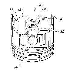
Turning first to Figures 1-5 of the draw-
ings, there is depicted a piston assembly 10 according
to the present invention for use in an engine. Broad-
~ ly stated, as shown in Figures 2, 4, and 5 the piston
assembly 10 includes a piston body 12 and a pre-formed
liner 24. Conventionally, the piston body 12 includes
a crown 14, a skirt 16 extending from the crown 14,
and a pair of gudgeon pin bosses 18, 20 connected to
the skirt 16. The crown 14, skirt 16, and bosses 18,
20 define an interior surface 22 of the piston body
12. The liner 24 is comprised of a contimlum of sec-
tions thereof 14', 16', 18', 20' (Figures 6-9) which
are respectively juxtaposed with the crown 14, sklrt
16, and bosses 18, 20.
The interior surface 22 is virtually com-
pletely covered with the cast-in, pre-formed liner 24.

FMC 0529 PUS -5- 21312~
92-1055
The liner 24 adds strength and dimensional stability
during casting, machining, engine assembly, and in
service. At the same time, piston weight is reduced
for a given volume without sacrificing strength.
Preferably, the liner 24, as depicted in
Figures 6-9, is formed of one piece. Alternatively,
the liner 24 may be comprised of a plurality of pieces
if a rib or support structure within the piston body
12 needs to be accommodated.
Preferably, the liner 24 is formed from a
material selected from the group consisting of steel,
aluminum, plastic, a metal-matrix composite, and mix-
tures thereof. Ideally, their coefficients of thermal
expansion are less than the material selected for the
piston body 12 so that upon solidification of the
material, the liner becomes squeezed and retained in
place.
Structurally, the liner 24 is a metallic
insert which has contours which conform the liner 24
to the interior surface 22 of the piston body 12.
To mate the liner 24 to the piston body 12,
a bonding means 26 (Figure 8) is provided. The bond-
ing means 26 comprises, for example, a corrugated
surface defined upon the liner 24 so that voids are
formed therewithin. In this embodiment, the voids
serve as anchoring sites within the liner 24 so that
upon solidification, the molten material of which the
piston body 12 is formed flows into the anchoring
sites. Upon solidification, the material becomes
bonded to the liner 24. Alternatively, the bonding
means 26 may comprise undercut grooves defined within
the liner which confine the molten material, so that
~he material upon solidification securely engages the
liner 24. In another embodiment, the bonding means 26
comprises a coating which is distributed at least

FMC 0529 PUS -6- 2~312~
92-1055
partially within the liner 24, or bonded to the sur-
face of the liner 24, so that the coating fuses with
the molten material upon pouring.
As best illustrated in Figures 2, 4, 5, 7,
and 9, the liner 24 further includes a locator tab 28
which mates with a center core in a mold to position
the liner 24 within the mold.
Turning now to Figure lO, a method of manu-
facturing a piston assembly for an engine is dis-
closed. The liner 24 is first formed using conven-
tional ~echniqiues, such as stamping. A permanent
metal mold is then provided with a cavity for defining
the outer shape of the piston body 12. Next, the
liner 24 is located within the cavity so that a space
is created between the cavity and the liner 24. The
mold is then closed.
Molten material of which the piston body 12
is formed is then poured into the space between the
cavity and the liner 24. The liner 24 defines the
interior surface 22 of the piston body 12 and tends to
direct the flow of molten material into the cavity,
thereby improving solidification. After solidifica-
tion, the mold is opened and the piston assembly 10,
- including the piston body 12 united with the liner 24,
is removed from the mold.
These method steps may be supplemented by
pre-heating the mold and the liner 24 before filling
the spacé with the molten material. Additionally, the
disclosed method comprehends the step of allowing the
mold to cool before enduring solidification so that
the material shrinks to encompass the liner.
To locate the liner 24 within the mold, one -
or more cores (not shown) are inserted within the mold
to position the liner 24 in relation to the cavity.
;: ., .. . . ~. . . :.. -.. , .. , : : .: : ,. - ... .. ..
., ... .. , "~,, . ~. ,. ,," .,, ~ . ,

FMC 0529 PUS -7- 2 1 3 1 2 ~ 4
For added strength arld dimensional stabili-
ty, the liner 24 may be bonded to the piston body 12.
Bonding may take the form of providing a corrugated or
serrated configuration to the liner surface. Addi-
tionally, under-cut grooves may be provided on the
surface of the liner 24 which will lie in contact with
the molten material. Such grooves can be machined or
rolled into the liner surface.
Alternatively, a coating may be diffusion
bonded to the surface of the liner 24. Such a coating
would fuse with the molten material upon pouring the
piston body 12. Where the molten material is alumi-
num, an aluminized liner could be used in which a
steel liner is coated with an aluminum and silicon
alloy. Aluminizing imparts corrosion resistance and
heat resistance to the steel liner. Another means of
bonding may be provided by perforating the liner in
selected areas. Where this technique is used, the
piston mold's center cores may be designed to contact
the liner in the perforated areas. In that event, the
molten material fills the perforations during pouring.
When the piston body 12 is cast from an
aluminum alloy, typical temperatures to which the
permanent metal molds are pre-heated are 400-500F so
that, in the cavity area, the temperature is about
250-300F. Preferably, the liner 24 is pre-heated to
200-300F. Realistically, the solidification time
for pistons cast from an aluminum alloy may be about
60-72 seconds.
While the best mode for carrying out the
invention has been described in detail, those familiar
with the art to which this invention relates will
recognize various alternative designs and embodiments

Representative Drawing
A single figure which represents the drawing illustrating the invention.
Administrative Status

2024-08-01:As part of the Next Generation Patents (NGP) transition, the Canadian Patents Database (CPD) now contains a more detailed Event History, which replicates the Event Log of our new back-office solution.

Please note that "Inactive:" events refers to events no longer in use in our new back-office solution.

For a clearer understanding of the status of the application/patent presented on this page, the site Disclaimer , as well as the definitions for Patent , Event History , Maintenance Fee  and Payment History  should be consulted.

Event History

Description Date
Inactive: IPC from MCD 2006-03-11
Application Not Reinstated by Deadline 2002-09-03
Time Limit for Reversal Expired 2002-09-03
Deemed Abandoned - Failure to Respond to Maintenance Fee Notice 2001-08-31
Letter Sent 2001-03-30
Inactive: Application prosecuted on TS as of Log entry date 2001-03-30
Inactive: Status info is complete as of Log entry date 2001-03-30
Request for Examination Requirements Determined Compliant 2001-02-28
All Requirements for Examination Determined Compliant 2001-02-28
Application Published (Open to Public Inspection) 1995-03-08

Abandonment History

Abandonment Date Reason Reinstatement Date
2001-08-31

Maintenance Fee

The last payment was received on 2000-08-01

Note : If the full payment has not been received on or before the date indicated, a further fee may be required which may be one of the following

  • the reinstatement fee;
  • the late payment fee; or
  • additional fee to reverse deemed expiry.

Patent fees are adjusted on the 1st of January every year. The amounts above are the current amounts if received by December 31 of the current year.
Please refer to the CIPO Patent Fees web page to see all current fee amounts.

Fee History

Fee Type Anniversary Year Due Date Paid Date
MF (application, 3rd anniv.) - standard 03 1997-09-02 1997-07-10
MF (application, 4th anniv.) - standard 04 1998-08-31 1998-07-09
MF (application, 5th anniv.) - standard 05 1999-08-31 1999-08-10
MF (application, 6th anniv.) - standard 06 2000-08-31 2000-08-01
Request for examination - standard 2001-02-28
Owners on Record

Note: Records showing the ownership history in alphabetical order.

Current Owners on Record
FORD MOTOR COMPANY OF CANADA, LIMITED
Past Owners on Record
JOHN LAWRENCE GORSKY
WILLIAM HUDY
Past Owners that do not appear in the "Owners on Record" listing will appear in other documentation within the application.
Documents

To view selected files, please enter reCAPTCHA code :


To view images, click a link in the Document Description column (Temporarily unavailable). To download the documents, select one or more checkboxes in the first column and then click the "Download Selected in PDF format (Zip Archive)" or the "Download Selected as Single PDF" button.

List of published and non-published patent-specific documents on the CPD .

If you have any difficulty accessing content, you can call the Client Service Centre at 1-866-997-1936 or send them an e-mail at CIPO Client Service Centre.

({010=All Documents, 020=As Filed, 030=As Open to Public Inspection, 040=At Issuance, 050=Examination, 060=Incoming Correspondence, 070=Miscellaneous, 080=Outgoing Correspondence, 090=Payment})


Document
Description 
Date
(yyyy-mm-dd) 
Number of pages   Size of Image (KB) 
Representative drawing 1999-07-12 1 8
Abstract 1995-06-04 1 22
Drawings 1995-06-04 3 114
Claims 1995-06-04 5 186
Description 1995-06-04 7 359
Acknowledgement of Request for Examination 2001-03-29 1 178
Courtesy - Abandonment Letter (Maintenance Fee) 2001-09-30 1 185
Fees 1998-07-08 1 54
Fees 1997-07-09 1 54
Fees 1996-06-26 1 42