Note: Descriptions are shown in the official language in which they were submitted.
~131~8
, . .
1 METHOD AND APPARATUS FOR LONGITUDINALLY
2 FOLDING A PRINTED WEB IN A PRINTING PRESS
3 The present invention generally relates to the art
4 of web printing, and more particularly relates to longitu~
dinally folding a web of printable material as it travels
6 through a web printing press~
7 It is well known that in-line web printing presses
8 are used to print many kinds of printed materials, including
9 magazines and newspapers. These printing presses can print
extremely high quality printed material on high quality heavy
11 stock paper webs that inherently have high strength charac-
12 teristics.
13 When heavy stock paper is used in this type of
14 press, the range of values of acceptable tension that the web
encounters while it is run through the printing press can be
16 quite large without experiencing breakage of the web. On the
17 other hand, when newspapers are being printed on various
18 newsprint grades of paper, the tension levels that can be
19 applied to the web are considerably less than are possible
with the thicker webs.
21 While the tension levels that can be applied to the
22 heavier grade paper webs can be much greater than that applied
23 to newsprint, web breakage in the press is a concern regard~
24 less of the strength of the paper web being printed. This is
due in part because of the nature of paper in that if tension
~" - ' ~-' . ; '
' ~ ~ ~' . ' -- :
~- - - , - ' ,' ~ , ' -- ' '- , ~ :
r
~ 2131 ~S8
1 is evenly distributed across a web being printed, which may be
2 55 inches or more, the web may be capable of withstanding
3 tension levels in excess of ten pounds per lineal inch. This
4 can result in a tension totaling more than 500 pounds for a 55
inch wide web.
6 For much lighter grades of paper, such as newsprint,
7 the tension levels may approach four pounds per lineal inch of
8 width before the web would break. However, the nature of the
9 force being applied to webs as they are run through a printing
press is such that a malfunction of the press will result in
11 an uneven application of tension to the web being applied. In
12 fact, it is generally the rule rather than the exception that
13 forces that are applied during the printing process in an in-
14 line web printing press which results in a breakage of the web
is a result of a focusing of force on a very small area of the
16 web which causes it to break. Once the web is initially
17 broken, the forces often cause the break to rapidly spread and
18 extend across the entire web and completely sever it.
19 It is common and well known in the printing art to
apply water to a web during the printing process for the
21 purpose of isolating the ink, since many commonly used inks do
22 not mix with water. This is generally the case in the
23 printing of newspapers and the water is sprayed onto the
24 impression cylinder in the printing unit once the printing
press reaches a predetermined operating speed during startup
26 of a printing run.
27 The initial spraying of the impression cylinder
28 often results in a greater amount of water being initially
29 applied and the water can accumulate in the gap between the
plates where they are attached to the impression cylinder.
31 This results in a wicking action by the web which removes the
32 water from the gap during operation. It also causes a line of
33 wetness to occur in the web which extends across at least a
34 large portion of the width of the web ~or a number of
impressions, which may approach six or seven impressions
21316~8
1 before the water is removed from the gaps.
2 The presence of this line of wetness has the
3 undesirable result of substantially reducing the tensile
4 strength of the web across such a line. For larger webs which
may approach or exceed 55 inches in width, it is common to
6 offset the printing plates along the printing roller into two
7 distinct sections so that a single gap will not extend across
8 the entire width in a single line. Thus, if they are offset
9 on a half-to-half relationship, then a gap at a single
longitudinal location would only extend across approximately
11 one-half of the web. This generally provides sufficient
12 insurance against fracturing of the web due to the wetness
13 that may be present.
14 Once the press continues to increase in operating
speed, the water accumulation is generally not experienced.
16 Thus, the water accumulation is generally a startup problem,
17 but could be a significant one if less than a full web were
18 being printed, or if there were no effective offsetting of the
19 gap in the longitudinal direction for a web or web portion
that was being processed through a printing press and which
21 experienced considerable tension forces.
22 It is also known and common in the web printing art
23 that one or more webs are printed by various printing units
24 and then be combined in a forming station. A forming station
may receive multiple webs and split the web into two or more
26 smaller ~; ~n-~ioned widths and then apply those widths to a
27 folder which folds the web portions being fed to it into
28 smaller sections, such as the sections of a newspaper.
29 The forming station then cuts the web into discrete
lengths and applies additional folds to make a folded
31 newspaper. The web is supplied by one or more supply rolls
32 which feed the web to the printing units and the web is then
33 run to the former. The supply rolls generally have a means
34 for applying a resistive force to the unwinding of the web
from the rolls and this has the effect of applying tension to
--3--
213165~
1 the web throughout the printing press. However, the forming
2 means generally applies the greatest tension to the web and in
3 a newspaper printing operation, the forming or former means
4 can apply tension to the web that may range from approximately
one-half pound per lineal inch to two pounds per lineal inch.
6 Thus, for a 55 inch web, the tension applied to the entire web
7 could range from 27 to 110 pounds. Obviously, if the web is
8 split into two half sections, the tension for each half
9 section would be approximately 13-1/2 pounds to approximately
55 pounds.
11 The design of the forming means is such that tension
12 is generally uniformly distributed and tension for a full 55
13 inch web may be within the range of 27 to 110 pounds on the
14 web. This would be approximately 13 to 55 pounds if the web
were split into two sections of approximately 27-1/2 inch
16 width. A 27-1/2 inch width web would then be folded into two
17 equal sections and would generally result in four pages of a
18 newspaper.
19 Modern printing presses generally accommodate up to
four forming units which results in a m~; mllm of eight
21 sections that can be simultaneously printed. If more sections
22 are to be printed, then it has to be done on a separate press
23 or has to be done subsequently on another press run of the
24 same press and the additional sections then must be combined
with the sections made during the original press run. While
26 it may be possible to put in additional printing units and
27 additional forming units to the location where the other
28 forming units are present, this requires a much higher
29 elevation in the press room which is usually not present and
the roof may literally have to be raised to accommodate such
31 a construction. The cost of such reconstruction is often
32 considered prohibitive.
33 If, however, a longitudinal fold can be applied to
34 a printed web upstream of the formers, the folded product
could be combined at the former and additional sections of a
-4-
1 newspaper, for example, could be printed by the same printing
2 press during a single press run. To accomplish such a
3 longitudinal fold, it has been contemplated to use a plow
4 folding mechanism to fold one or two webs after they have been
printed, but it is easier said than done because of the
6 concentration of force that occurs in a plow folding
7 structure, whether it be a rotary plow folder or a plow
8 folding shoe.
9 Due to the fact that a web can be folded over onto
itself to form four pages of a newspaper or if two webs were
11 folded to produce an eight page section, the inherent nature
12 of a plow folder results in one-half of the web being folded
13 not having any tension whatsoever applied to it during the
14 folding operation. Thus, the tension that would otherwise be
present in the complete web would be concentrated to one-half
16 of the web, thereby doubling the tension per lineal inch being
17 applied to the web. Because of the relatively low strength of
18 newsprint, such plow folding efforts have not been successful.
19 The attempts have been exacerbated by the fact that
a web that is to be folded would necessarily have a width
21 whereby the printed indicia would extend across the entire
22 width being folded and any gap between the impression plates
23 would extend the full width of the web. Thus, if water were
24 present in the gap, which would decrease the strength of the
web, then a break could easily occur during the folding
26 operation or downstream of it toward the former.
27 Accordingly, it is a primary object of the present
28 invention to provide an improved method and apparatus for
29 longitudinally folding a web of printable material in a
printing press upstream of a forming unit.
31 Another object of the present invention is to
32 provide an improved method and apparatus for applying a
33 longitudinal fold to one or two webs of an in-line printing
34 press downstream of the printing units at a location between
the printing units and an output unit, such as a forming unit.
tt~
213~658
,
1 A more detailed object is to provide such a method
2 and apparatus for plow folding a relatively fragile web such
3 as newsprint in a newspaper printing press wherein the folding
4 is performed at a location between the printing unit and the
newspaper forming unit.
6 Another object of the present invention is to
7 provide such an improved method and apparatus for
8 longitudinally folding a web of printed material, which
9 apparatus can be retrofitted into existing printing presses
without requiring any significant modification to the printing
11 presses or any structural change to the building in which the
12 press is located.
13 Another related object of the present invention is
14 to provide such a method and apparatus which effectively
controls the tension of the web in a folding zone.
16 Yet another related object is to provide such a
17 method and apparatus whereby the tension levels that are
18 normally experienced in the printing press are relatively
19 unaffected, but the web within the folding apparatus is
isolated and controlled so that folding can be accomplished
21 reliably and accurately.
22 Still another object of the present invention is to
23 provide such an improved method and apparatus for longitu-
24 dinally folding the web in an in-line printing press prior to
the folding unit by precisely controlling the tension of the
26 web when the web is in a folding zone that is defined by
27 isolating the tension within the zone from both the upstream
28 and downstream portions of the web outside of the zone.
29 Another object of the present invention is to
provide such an improved apparatus which utilizes a processing
31 means that contains a control algorithm that utilizes
32 proportional, integral and derivative terms for accurately
33 controlling the apparatus so that the tension in the web
34 within the folding zone can be controlled within close
tolerances.
-
-: ~ i, .
-6- ~
2~3.~6~8
1 Yet another object of the present invention is to
2 provide such an improved method and apparatus which
3 effectively controls the tension in the web to vary the
4 tension both within the folding zone and downstream thereof in
a manner whereby tension is maintained at a lower level than
6 during normal operation for a web that has been initially
7 sprayed with water during startup of the press, or during a
8 jogging or other slow press speed operation. This enables a
9 portion of the web to clear the press at lower tension levels
to m;n;ml ze the potential for breakage.
11 Still another object of the present invention is to
12 provide such an improved method and apparatus which folds two
13 combined webs at a folding zone, and yet controls the tension
14 of the combined webs in a manner whereby a predetermined
maximum desirable tension on either of the separate webs is
16 not exceeded.
17 Other objects and advantages of the present
18 invention will become apparent upon reading the following
19 detailed description, while referring to the attached
drawings, in which:
21 FIGURE 1 is a side view of apparatus embodying the
22 present invention;
23 FIG. 2 is a block diagram of the control circuitry
24 that is part of the apparatus of the present invention;
FIG. 3 is a plan view of one roll that is part of
26 the present invention; and,
27 FIG. 4 is a block diagram of a printing press having
28 the apparatus embodying the present invention installed.
29 Detailed Description
Broadly stated, the present invention is directed to
31 a method and apparatus for longitudinally folding a web of
32 printed material within an in-line printing press. The method
33 and apparatus is adapted for use in a conventional in-line
34 printing press that is of the type which has a web supply
unit, a plurality of printing units, typically four color
2~ 3165~
1 printing units, and a former unit locat~d at the downstream
2 end of the printing press.
3 The apparatus of the present invention is positioned
4 downstream of the printing unit and upstream of the former
unit or other output unit. The method and apparatus is
6 adapted to control the tension of the web within the folding .-
7 apparatus which may be referred to as a folding zone where the
8 one web (or two combined webs) is folded in the longitu~l n~l
9 direction.
While the apparatus is preferably used during the
11 printing of the web in a printing press, it is also
12 contemplated that the web being folded can be preprinted and
13 then be run through the folding unit and combined with other
14 webs.
The apparatus effectively isolates the tension of
16 the web within the folding zone so that its tension is reduced
17 relative to the tension that is normally present in the web
18 upstream of the folding zone as well as downstream of it.
19 This is accomplished by securing the web at an input cylinder
as well as an output cylinder and carefully controlling the
21 speed of the either the input cylinder and/or output cylinder
22 in a manner whereby the tension within the folding zone is
23 maintained at a predetermined range of values. This is
24 accomplished by sensing the tension in the web at one or more
locations, preferably in the input side of the folding zone,
26 i.e., the tension in the web after it leaves the input ~ -
27 cylinder. The web is preferably secured by wrapping the web
28 over the cylinders. However, it should be understood that it
29 can also be secured by utilizing a nip roller in combination
with the input cylinder as well as the output cylinder to
31 impinge the web and thereby hold it.
32 The input cylinder as well as the output cylinder
33 are preferably driven by drive means that are controlled by
34 electrical signals generated by processing means that utilizes
as its input the measured tension in the web downstream of the
-8- - ;
- : ~
;', . ?, : ~y,. .: .. . ; ~ .
' ~ ' '' '' : :': : '
'', ,'-'' i'''' : ~"''
?. : '' ': , : . :
' ' : ' ' . ' " ' :: : : ' : : '' ' ~ .- ' '
~ ' ~ . . ~' ' , ' ~ "' '';- :' : ' :;,
2131~58
1 input cylinder. sy driving the output cylinder which is
2 designed to grab the web relatively tightly so that it will
3 not slip on the surface of the output cylinder, the tension
4 upstream of the output drive cylinder can be reduced relative
to the downstream side and in this way, control the tension
6 within the web. The tension can also be controlled by driving
7 the input cylinder at a speed that is carefully controlled
8 relative to the web speed.
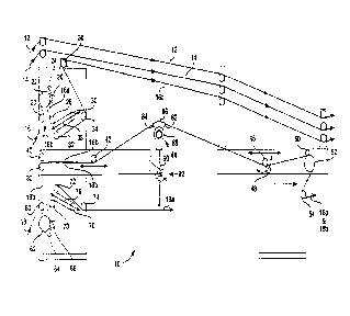
9 Turning now to the drawings, and referring to FIG.
1, a folding unit, indicated generally at 10, is shown and is
11 adapted to receive one or more webs of paper at the left side
12 which move through the apparatus 10 to the right side where
13 the webs would pass to downstream units, such as a forming
14 unit, an in-line finishing unit or other type of output unit.
The apparatus 10 has four webs being fed to it, namely webs
16 12, 14, 16 and 18. The webs originate from supply rolls 15
17 and are fed through printing units 17 where printing is done
18 before the webs reach the apparatus 10 of the present
19 invention. The webs then are fed to an output device such as
a former or forming unit 19.
21 It should be understood that the webs 12 and 14 are
22 webs that come from the individual printing units 17 and are
23 not folded so they are merely bypassed above the apparatus 10
24 and would pass to downstream portions of the printing press,
such as the former unit 19. The web 16 is introduced to the
26 apparatus 10 by passing beneath a roll 20 and over roll 22.
27 The web is nipped by a roll 24. A slitter mechanism 26 slits
28 the web into two segments, one of which is identified as web
29 16a and this web passes around roll 28, 30, 32, 34 and 36
where it is fed to the downstream portions of the printing
31 press, such as the former.
32 The roll 30 is moveable in the direction of the
33 arrows 38 for the purpose of adjusting the position of the web
34 relative to other webs so that the printed indicia is properly
aligned when it reaches the downstream portion of the printing
21316~j~
1 press.
2 The other portion of the web is identified as 16b
3 and this web passes around roll 40, as well as roll 42 where
4 it then is fed to a folding means, indicated generally at 44,
where the web is longitudinally folded onto itself. The
6 folded web is then fed to an adjustable nip defined by rolls
7 46 and 48 and it then passes under roll 50 and wraps around
8 exit drag roll 52 and roll 54, where it exits to the down-
9 stream portion of the printing press.
If two webs are being folded, then the web 18 would
11 be introduced to the apparatus 10 as shown in FIG. 1.
12 However, if only one web were being folded, then the web 18
13 would not be present. If web 18 is present, it is wrapped
14 around a roll 60 as well as roll 62 that is held by a nip roll
64. The slitter 66 slits the web 18 into two separate widths
i6 18a and 18b. Web 18a is passed around rolls 68, 70, 72 and 74
17 where it exits the apparatus 10 and is fed to the former or
18 other output device. As in the case of the roll 30, roll 70
19 is movable in the dire~tion of the arrows 76 for adjusting the
position of the web relative to other webs that are fed to the
21 former. The web portion 18b is fed to a roll 80 where it is
22 aligned and brought into contact with the web 16b so that two
23 layers of web will be applied to the folding station 44 where
24 they are folded.
The folding means 44 has a folding shoe 82 over
26 which the web or webs travel with the shoe 82 having an
27 arcuate portion 84 for initially receiving the web and a flat
28 portion 86 which merges with the curved portion 84. As shown
29 in FIG. 1, the shoe 82 is supported by a mounting structure 88
and it is connected to a rod structure 90 that is operatively
31 connected to an adjusting means, indicated generally at 92,
32 which has a handle that permits the entire structure to be
33 raised or lowered to change the angular orientation of the web
34 relative to the shoe 82. The web portion that is to be folded
under will not contact the shoe 82 so that the upper portion
-10-
- :, , ,, ,, .:
21316~X
1 of the web which does contact the shoe must support the full
2 tension that is applied by the apparatus. The side not in
3 contact has no tension applied to it and it folds underneath
4 the upper portion in a manner that is well known in the plow
folding art. While the shoe construction is shown, it should
6 be understood that a rotary plow construction can be used, and
7 in that event the structure 88 may rotate and be in contact
8 with the web. The structure 82, 84 and 86 shown would not be
9 present with such an embodiment. It is also contemplated that
a combination of a rotary plow and a shoe can be used.
11 In accordance with an important aspect of the
12 present invention, the portion of the webs 16b and/or 18b that
13 are within the folding apparatus 10 are effectively isolated
14 from the standpoint of tension from both the portion of the
webs that are upstream of the input rolls 22 and 62 as well as
16 downstream of the output or exit drag roll 52. This is
17 accomplished on the input by wrapping the web 16 around roll
18 22 through an arcuate path of approximately 180~ which is
19 similarly done with respect to the web 18 being wrapped around
roll 62. This effectively isolates the tension on the
21 upstream side from the tension of the web that exits the rolls
22 22 and 62.
23 Similarly, the exit drag roll 52 in combination with
24 the roll 54 isolates the output tension of the web from the
tension upstream of the roll 52. This is in part due to the
26 fact that the exit drag roll 52 is preferably provided with an
27 abrasive surface to prevent the web from slipping during
28 operation. In this regard, the abrasive surface of the roll
29 52 can be achieved by various means, preferably such as by
applying a carbide material to the surface. Alternatively,
31 diamond particles may even be used to provide an extended wear
32 surface. A sandpaper surface, while not expected to provide
33 for the desired extended wear, could have a longer useful life
34 if the sandpaper has a spring steel substrate rather than a
cloth substrate. As an additional alternative, the surface of
~1316.5~3
1 the roll 52 may be knurled or provided with a grated wrap type
2 of material, although the carbide abrasive surface is
3 preferred.
4 It is also preferred that the surface of the roll 54
have a number of outwardly extended or ribbed portions 94 as
6 shown in FIG. 3. It has been found that these rib portions
7 prevent web breakage of newsprint particularly when two webs
8 16b and 18b are folded together. It should be understood that
9 one of the webs will be completely sandwiched between outer
layers of the other web and when the combined webs are wrapped
11 around a cylinder, the layers that are furthest away from the
12 cylinder surface must travel farther than the inner layers.
13 This has been found to create tension problems that has
14 resulted in slippage of the trapped or inside web relative to
the other and eventually resulted in a web break. By using
16 the ribbed cylinder 54 at the location illustrated, the
17 problem is substantially eliminated.
18 In accordance with another important aspect of the
19 present invention, the exit drag roll 52 is driven at a speed
that is carefully controlled to achieve the desired tension
21 control of the web being folded while it is in the apparatus
22 10. By virtue of the effective tension isolation that is
23 achieved by rolls 22, 62 and 52, the speed that the roll 52 is
24 driven can be used to adjust the tension of the web that is
passing over the folding means 44. Stated in other words, if
26 the roller 52 is driven slightly slower than the web would
27 otherwise travel between the printing units which are upstream
28 of the apparatus 10 and the former which is downstream of the
29 roll 52, the tension in the web within the apparatus, i.e.,
within the folding zone or folding station, can be reduced.
31 Conditions within printing presses can change
32 dramatically depending upon the operating conditions and other
33 circumstances. The modulus and stretchability of paper will
34 change depending upon the amount of ink and the amount of
water that is applied to the web. The conditions will also
-12-
.. . . . .. . ... . . . ~ . .. .. .. ~ .. . .. . .. .
: . . : ;: . i:
:,~ :: '-: ' .. : .
,; . .. ........ .. ...
21316~8
1 change depending upon the direction of fiber in the paper, the
2 thickness of the paper, as well as the temperature and
3 humidity within the press room. All of these factors affect
4 the tension that may be present in the web. Additionally, the
setting of the former and other settings within the press will
6 have an effect on the tension of the web.
7 It is common that a tension level on the order of 40
8 pounds would be applied upstream of the former. When a press
9 is being set up, the supply rolls which generally unifor~mly
have a tension applying mechanism, usually do not apply
11 tension to the press until the paper is threaded through the
12 former. Once this is completed, then tension is applied to
13 the supply reels to provide a desired tension on the web. On
14 one commonly used structure, the tension is applied on the
supply reels by tightening bands which contact the outer
16 surface of the roll of paper to resist it feeding the web to
17 the printing units, with the amount of force being applied to
18 the bands controlling the amount of tension that is produced.
19 In accordance with the present invention, a tension
level on the order of 40 pounds is unacceptably high and will
21 generally result in breakage of the web. This is due in part
22 because the portion of the web that is folded is less than the
23 full width, often 1/2 of the web 16 or 18 and that 1/2 web
24 portion 16b and 18b which is folded effectively has the
tension concentrated in the upper side of the web when it
26 passes over the folding shoe 82. This concentration of
27 tension necessarily creates additional breakage problems if
28 the tension of the web within the apparatus is not reduced.
29 To this end, the apparatus of the present invention
has a control system for controlling the feed by which the
31 exit drag roll 52 operates to achieve a tension of the web
32 that is applied to the folding means 44 within the range of
33 approximately 6 to 13 pounds, and preferably about 10 pounds
34 during production in the printing of a newspaper. This is a
significant reduction in tension compared to the 40 pound
213~6.~
1 level that may be present at the former.
2 To control the tension of the web in the apparatus
3 10, load cells or tension transducers are used to measure the
4 tension at one or more predetermined locations within the
apparatus. While the tension may be sensed at a location near
6 the input or the output, or both, one preferred embodiment has
7 load cells operatively connected to rolls 22 and 62 for
8 measuring the tension at the input to the apparatus 10. As is
9 generally known to those skilled in the art, the load cells
should be applied at a location whereby the angle of the web
11 will not change during operation and for this reason, the
12 rolls 22 and 62 have a constant angular orientation of wrap of
13 the web around these rolls.
14 It is preferred that the tension in the web 16b and
18b which are the portions that are downstream of the rolls 22
16 and 62 be at a tension of approximately 10 pounds which
17 compares to a commonly applied tension upstream of these same
18 rolls that is in the neighborhood of approximately 18 pounds.
19 While the apparatus embodying the present invention is
effective to operate reliably with tension being measured in
21 the web at the input by the tension transducers located in
22 cooperation with rolls 22 and 62, a tension sensor transducer
23 could be connected to the exit drag roll 52 or even on the
24 folding mechanism 44 itself.
When the press is started up, it is necessary to
26 hold the web at the exit drag roll 52 for a time until the
27 press increases in operating speed so that tension levels are
28 stabilized. To hold the web during startup, the roll 50 is
29 controllable to apply a variable force to the web and hold the
web tightly to the surface of roll 52. Once the press reaches
31 a predetermined operat ng speed, the cylinder 50 is preferably
32 released so that it is out of contact with the web during
33 normal operation. It should be understood that the threshold
34 speed at which the roll 50 is removed can be sensed and the
retraction of the roll 50 can easily be automatically
-14-
:. .. , . .... - .... , ., . . . ., ,,,.. : ..
. . . , :
~- . , ... ~ .
- i .. . . ... ::
21.~16~8
1 controlled.
2 In accordance with another important aspect of the
3 present invention and referring to FIG. 2, there is a block
4 diagram of the control circuitry that is used to control the
tension of the web within the apparatus, which can be
6 considered a folding zone or station. The circuitry comprises
7 a processing means which is preferably a microprocessor 100
8 which functions as a controller for controlling the speed of
9 operation of the exit drag roll 52 as well as other functions.
The microprocessor 100 receives signals from a
11 tension s~nsor 102 via line 104 with the tension sensor 102
12 being a tension transducer that is operatively connected to
13 the roll 22. A second tension sensor 106 associated with the
14 roll 62 provides an electrical signal on line 108 that is
indicative of the tension of the web 18b and it is also
16 applied to the microprocessor 100. The microprocessor 100
17 also receives a signal indicative of the press speed from a
18 tachometer or the like 109, which may the same as that
19 indicated in the lower left portion of FIG. 2.
A predefined set point is shown by block 110 and it
21 is interconnected via line 112 to the microprocessor 100 and
22 this defines the input tension of the web 16b and 18b. Given
23 the fact that the input tension of the web 16 and 18 that are
24 fed to the apparatus 10 is generally approximately 18 pounds,
the set point is the value which corresponds to the tension
26 level that is desired, which is preferably in the range of
27 approximately 10 pounds. However, the line 112 is shown with
28 arrows in both directions for the purpose of having the
29 microprocessor 100 change the set point as a function of press
speed, if desired. When the press is initially started up, it
31 is preferred that the tension in the web be reduced below 10
32 pounds until the operation stabilizes and when it is running
33 faster, the tension can be gradually increased. However, the
34 range of desirable tension is within 7 to approximately 12
pounds.
-15-
21 31 6~B
1 The microprocessor 100 performs a controlling
2 function and the control algorithm that is embedded in
3 associated memory of the microprocessor is preferably a
4 proportional/integral/derivative controller which produces a
control signal on line 114 which extends to a multiplier 116
6 that varies the control signal as a function of press speed.
7 The control signal on line 14 is multiplied by a signal on
8 line 118 that is also applied to the multiplier 116 and an
9 output signal is produced on line 120 that extends to a
summing junction 122, the other input of which is provided by
11 a line 124 from a potentiometer 126. The potentiometer 126 is
12 conr.ected to the output of an amplifier 128 having a positive
13 gain of 1. The output of the amplifier 128 appears on line
14 130 and this is applied to one end of the potentiometer 126 as
well as to another amplifier 132 having an output gain of -1
16 on line 134 and this is connected to the other end of the
17 potentiometer 126. The summing junction 122 provides an
18 output signal on line 136 that is applied to an amplifier 138
19 that drives a servo motor, the armature 140 of which is
mechanically attached to a mechanical differential 142 via a
21 mechanical connection schematically illustrated by line 144.
22 A tachometer 146 provides a tach signal to the amplifier 138.
23 The press drive line is physically connected to the
24 differential 142 and is schematically illustrated by line 148
and the correction signal being applied by connection 144
26 results in the output shaft of the differential which is
27 schematically illustrated by line 150 and which connects to
28 the exit drag roll 52 drives the roll 52 at a speed that can
29 vary up to 1-1/2~ faster or slower relative to the press drive
speed represented by line 148.
31 Since the speed of the web that is traveling through
32 the apparatus of the present invention is effectively
33 controlled by the rotation of the exit drag roll 52 and since
34 the speed of the web when last controlled before the web is
applied to the input of the apparatus 10 is that which is
-16-
: . . ~ .. , . . . - ~ . ....... .
.~ -: : . : .-
~1316~
,...
1 controlled by the blanket roll within the printing unit, it is
2 desirable if not necessary to match the speed of the outer
3 surface of the blanket roll to the surface speed of the exit
4 drag roll. This can be accomplished by the potentiometer 126 .
in the circuit having the plus and minus unity gain amplifiers
6 128 and 132.
7 While the correction signal from the microprocessor
8 mechanically controls a differential which effectively adds or
9 subtracts revolutions per minute to the press drive line 148,
the illustrated circuitry is dependent upon the use of a press
11 drive line or an extension of it to drive the exit drag roll.
12 However, it ~hould be understood that the exit drag roll can
13 be driven by a D.C. motor which would eliminate the need to
14 extend the press drive line to the folding apparatus. The
recently developed flux vector drive technology results in
16 D.C. motors that have superior control capability and can be
17 used in place of a mechanical drive of the type illustrated in
18 FIG. 2.
19 As previously mentioned, the microprocessor 100
utilizes a closed loop control that includes a proportional/
21 integral/derivative control loop to generate the control
22 signal on line 114. The proportional term is defined by the
23 equation
24 P-term = Kp * e(n)
where en is said input error signal which is the difference
26 between the signal that is indicative of the tension sensed by
27 either sensor 102 or 106 relative to the predefined set point
28 as determined by the block 110. The proportional gain factor
29 kp is preferably approximately 0.7.
The derivative term is defined by the equation
31 D-term = Kd * (e(n) - e(n-1))/T9
32 where e(n) is the difference between said measured tension and
33 said predetermined tension at sample time "n"; e(n-1) is the
34 difference at the previous sample time; and TB is the sampling
period. While sampling at a faster rate such as 100 samples
.
-17-
2~ 31G.58
1 per second results in more data being processed during ~ -
2 operation, it has been found that sampling at a rate of 10
3 samples per second is effective to provide reliable control.
4 The gain factor for the derivative term is relatively small
and may be on the order of 0.02 during operation.
6 With respect to the integral term, it is defined by
7 the equation
8 I-term = (Ki * e(n) * T~) + I-term(n-l)
9 where e(n) is the difference at sample time "n"; I-term(n-l)
is the I-term calculated at the previous sample time; and T~
11 is the sampling period, and in practice, an integral gain
12 factor ki is preferably approximately 0.6. However, it should
13 be understood that the gain factor ki does not have to be
14 constant, and may desirably vary depending upon operational
13 considerations. With regard to the gain factor ki, it may
16 desirably change as a function of web or press speed, i.e.,
17 the factor would be decreased as the press speed increased.
18 This gain factor ki may be zero, which would effectively
19 remove it as a controlling influence.
As previously mentioned, the application of force
21 being applied by the roll 50 can be automatically controlled
22 by the microprocessor 100 as a function of detected press --
23 speed from block 108 which represents a tachometer signal and
24 the microprocessor 100 can apply a signal on line 152 to a
retraction mechanism schematically illustrated by block 154.
26 In accordance with yet another important aspect of
27 the present invention, it should be appreciated that when two
28 webs are applied to the folding means 44, they are combined
29 into a single web as seen by the exit drag roll 52. If the
tension of each of the webs is measured, then the presence of
31 the two webs will result in the exit drag roll 52 applying a
32 greater force to the combined webs. Thus, if the tension on
33 each web is measured at the input at the desired value of
34 approximately 10 pounds, then the exit drag roll 52 would
apply a total of 20 pounds. However, if the input tension of
-18- ~ -
. .............................................. ... ..
. .
,, 21316,~g
"
1 the two webs is unequal, such a 20 pound tension could break
2 one of the webs which had a higher input tension. In the
3 event the webs are unevenly tensioned, the microprocessor 100
4 will compare the measured tension, and will not apply a
tension that represents the sum of the two tension values, and
6 in fact will not exceed the 10 pound tension level. This
7 insures that the web will not be broken by excessive tension
8 being applied.
9 In accordance with yet another aspect of the present
invention, the microprocessor 100 has the capability of
11 controlling the tension of the web during jogging and/or
12 startup when breakage of the web can occur due to high web
13 tension aberrations or web strength reducing conditions. For
14 example, the presence of water in the gap between the printing
plates may be present. If water is present, then the strength
16 of the web may be compromised for several impressions, perhaps
17 six to seven of them. Since the portion of the web that is
18 being folded will necessarily have a gap that extends across
19 the full width of the web being folded, the presence of water
may easily result in a web break. Since the microprocessor
21 100 receives a press speed signal, and since the initial
22 application of water is known to occur at a particular press
23 speed, the microprocessor 100 can reduce the tension in the
24 web downstream of the exit drag roll for a period of time that
is sufficient to pass the portion of the web which contains
26 the six or seven impressions that may have excessive water on
27 the web to m;n;m;ze the possibility of a web break. Once that
28 portion of the web passes through the former, the tension
29 control can be adjusted to normal running conditions.
Similarly, there are press running conditions that
31 can result in web breakage, such as during operation in a jog
32 mode of the press or during slow running during startup before
33 the impression rolls are 'on impression'. These circumstances
34 are independent of the water problem discussed above. In such
circumstances, there can be excessive tension applied to the
-19-
... . , .;, :, ; . ..... .. .. .
21316~
1 web which has the potential for breaking the web. The
2 microprocessor 100 can control the drag roll 52 to pull more
3 paper through the apparatus of the present invention and
4 thereby reduce the tension of the web between the drag roll 52
and the former, as well as within the apparatus itself. When
6 the press is then put 'on impression' and brought up to a
7 normal running speed range, the appropriate tension levels are
8 established as previously discussed.
9 From the foregoing, it should be appreciated that an
improved method and apparatus for longitudinally folding a web
11 within a printing press has been shown and described which has
12 many significant advantages. The invention is effective to
13 provide greater production from a printing press and can
14 significantly reduce operating costs. The invention is
reliable in its operation, even though relatively fragile
16 paper webs can be used, because of the novel and sophisticated
17 tension control that is accomplished.
18 While various embodiments of the present invention
19 have been shown and described, it should be understood that
various alternatives, substitutions and equivalents can be
21 used, and the present invention should only be limited by the
22 claims and equivalents of the claims.
23 Various features of the present invention are ~et
24 forth in the following claims.
-20-
.;. . , . :; ; ~ . ,; .~ - - . .