Note: Descriptions are shown in the official language in which they were submitted.
~ 2~ 31 7~ 0
POWER-ACTUATED MOTOR-VEHICLE 13OOR LATCH WITH ANTITHEFT MODE
SPECIFICATION
FIELD OF THE INVENTION
The present invention relates to a motor-vehicle door latch. More par-
ticularly this invention concerns such a doox latch which can be manually or power ac-
tuated.
BACKGROUND OF THE INVENTION
A standard motor-vehicle door latch such as described in US patent
4,974,886 or 4,978,154 for use on a vehicle door having inside and outside handles and
inside and outside locking elements has a housing, a latch fork pivotal on the housing and
engageable in a locking position with a door bolt to retain same and lock the door, inside
and outside operating levers pivoted on the housing and connected to the respective hand-
les, ancl inside and outside locking levers pivoted on the housing and connected to the
respective locking elements. An tlct~ ting lever operatively engageable with the -fork can
release same from the locking position and a link coupled to the locking levers is displace-
able thereby between a first position wherein the outside operating lever is coupled to the
~r.t~ ing lever for displi~r.~m~nt of the fork out of the locking position by actuation of the
outside operating lever and a second position wherein the outside operating lever is
decoupled from the Irt~ ting lever. Thus in the decoupled position actuation of the out-
side operating lever will not unlock the door. A central ~chli~ting unit has a motor whose
spindle carries a nut that can move an antitheft lever into an antitlleft position.
Mechanism connected between the antitheft lever, the inside levers, and the link decouples
CA 02131740 1998-12-10
the inside levers from the actuating lever in the antitheft position of the antitheft lever.
Thus in the antitheft position actuation of the inside levers will not be able to release the
fork.
US patent 5,149,156 describes an actuator for such a latch which has a
5 housing adjacent the lock, a reversible electric motor in the housing having an output shaft
extending along a motor axis, and an input gear fixed on the output shaft and rotatable
thereby about the motor axis. A threaded spindle extending in the housing along a spindle
axis adjacent the motor axis carries an output gear and a nut threaded on the spindle is
movable along the spindle axis on rotation of the spindle between a pair of axially offset
10 positions. A link connected between the nut and the lock can move the lock between its
locked and unlocked positions on displacement of the nut between its end positions. A
manual actuator, for instance an inside door-lock button, is coupled to the nut for manually
displacing the nut between its end positions. A rocker pivotal about the shaft axis at the
input gear carries a pair of connecting gears fl~nking and meshing with the input gear.
15 This rocker is pivotal between angled positions in each of which a respective one of the
connecting gears meshes with the output gear and through a central position wherein
neither of the connecting gears meshes with the output gear. A spring urges the rocker into
the central position so that torque transmitted to the rocker on rotation of the input gear
pivots the rocker depending on input-gear rotation direction into one of its angled positions
20 to couple the input gear to the output gear. Such an arrangement does not have, however,
an antitheft mode.
In U.S. Patent No. 5,419,597 by H. Brackmann et al the door latch has
inside and outside locking elements and an actuator having an electric motor with a
threaded output spindle. A drive nut is threaded directly on the spindle and
25 displaceable by the motor between unlocked, locked, and antitheft positions. An
inside lever assembly includes a first inside lever pivoted on the housing and connected
directly to the inside locking element for displacement jointly with the inside
- 2 -
2131740 :~
locking element between locked and unlocked positions and a second inside lever pivoted
on the first inside lever and coupled to the actuator drive nut for pivotal displacement
jointly therewith between unlocked, locked, and antitheft positions. A spring braced
between the first and second levers urges abutments on them into engagement with each
5 other so that when the abutments are spaced apart the spring is loaded. A coupling
mechanism in the housing which is connected to the first inside lever, the door handles, an
outside locking element, the actuator nut, and a fork release pawl. The mechanisrn
couples the release pawl to the door handles in the unlocked positions of the locking ele- ~ ~
ments and the actuator nut to permit operation of the release pawl by the handles. The ~.
10 mechanism decouples at least the outside handle from the release pawl in the locked posi-
tion of either of the locking elements or of the actuator nut and decouples the first lever
and both handles from the release pawl in the antitheft position of the actuator nut. The ~ -
disadvantage of this system is that the motor for the power actuator must be moved for
manual actuation of the latch.
: ::
OBJECTS OF THE INVENTION ~ ~:
' .~' '
It is therefore an object of the present invention to provide an improved
power-actuated antitheft-lock system. - .
Another object is the provision of such an improved power-actuated an-
titheft-lock system which overcomes the above-given disadvantages, that is which can be
20 manually actuated without having to reverse-drive the actuator motor, in other words with
easy manual actuation in spite of the possibility of power actuation. ~ ;
., , ~
21~17~V
SUMMARY OF THF, INVENTION
A motor-vehicle door latch according to the invention which is preferably
enclosed in a housing includes a latching element movable between a latched position
retaining a door bolt and an unlatched position releasing the door bolt, and a locking pawl
5 engageable with the latching element and displaceable between a locked position wherein
it retains the latching element in the latched position and an ~unlocked position wherein it
permits movement of the latching element into the unlatched position. Power actuation of
the latch is effected by a planetary-gear drive which is centered on an axis and includes a
reversible electric motor, a sun gear rotatable by the motor about the axis, at least one
10 planet gear meshing with the sun gear and orbitable about the axis, a planet carrier
rotatable about the axis and carrying the planet gear, and a ring gear meshing with the
planet gear and rotatable about the axis. An ac.t~ ting lever, preferably operable by a door
handle, is provided for selectively moving the locking pawl between the locked and un-
locked positions. A coupling means for releasably coupling the locking pawl with the
IS art--:lting lever is movable by a manually operable locking element and by the planet car-
rier between a coupling position wherein it couples the locking pawl with the actuating
lever for joint movement from the ~ullocked to the locked position and a decoupling posi-
tion wherein it permits movement of the ~ct~ting lever between its locked and ~unlocked -
positions independent of the locking pawl. An antithe-l't means for selectively moving the
20 coupling means between the coupling and decoupling positions is movable by the sun gear
between an antitheft-on position wherein it is engaged with the coupling means and retains
the same in the decoupling position and an antitheft-o-ff position wherein it is ~ çng~ged
from the coupling means permitting movement thereof between the coupling and decou
pling positions. The latch further includes means -for arresting the planet carrier in the an-
25 titheft-on position of the antitheft element.
:.
213174~
Thus with this system it is possible to mechanically actuate the latch when .- -
it is in the locked or unlocked position without affecting the planetary gear drive. - .
Furthermore, such manual actuation is fairly simple and easy.
In a pre-ferred embodiment, the coupling means includes a coupling element
for releasably coupling the locking pawl and the actuating member, and a locking lever. .
The coupling element is connected with and movable by the locking lever and the latter is
operable by the locking element and the planet carrier.
According to another preferred embodiment of this invention the latch has a
driver plate pivotal about a plate axis parallel to the planetary axis, formed with a slot -:
open radially of the plate axis, and coupled to the locking lever. A pin on the planet car- ~.
rier is engageable in the slot so that the planet carrier is coupled to the locking lever via
the pin and plate. This pin can pull wholly out of the slot to completely decouple the
locking lever from it.
The arresting means preferably includes a sector gear which is rotatable :
about a sector-gear axis, meshes with the ring gear, carries the antithe-ft means, and has a ~
lobe projecting radially of the sector-gear axis. The planet gear is preferably -formed with :
a recess complementary to the lobe which is engageable in the recess to arrest the planet
carrier when the antitheft means is in the antitheft-on position. The housing is provided
with abutments operatively engaged by the locking lever and antitheft element in the ~ ~:
locked, unlocked, and antitheft-on, antithe-ft-off positions, respectively.
BRIEF DESCRIPTION OF THE DR~WINGS
The above and other objects, features, and advantages will become more
readily ~p~t;lll from the following description, reference being made to the accolllp~llyillg
drawings in which~
- .
..
. , .
21317~
FIG. 1 is a side partly sectional view of the latch according to the invention
in the locked and antitheft-o:ff positions;
FIG. 2 is a large-scale view of a detail taken along section line Il--II of
FIG. 1;
FIG. 3is a vertical section corresponding to a detail of FIG. 1 but along a
.lirr~lGIll plane and showing the system in the unlocked and antitheft-off positions;
FIG. 4 is a partly diagrammatic large-scale view of a detail of FIG. 1 in the locked and
antitheft-on positions;
FIG. S is a section taken along line V--V of FIG. 4 with line IV--IV showing the section
plane of FIG. 4;
FIG. 6 is section taken along line VI--VI of FIG. 5, taken in the opposite
direction as FIG. 4; and
FIGS. 7 through 14 are views like FIG. 3 showing parts of the latch in
different positions.
SPECIFIC DESCRIPTION
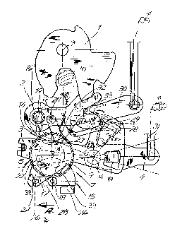
As seen in FIG. I a preferred embodiment of a motor-vehicle door latch ac-
cording to the invention in use engages a door bolt 45 that is mounted on a vehicle door
post (not shown) and can be releasably captured by a latching element such as a latch fork
I pivoted at lA on a latch housing 46 affixed to a vehicle door (not illustrated). The latch
fork I is retainable in the illustrated latched position by a conventional latch pawl 2 in the
manner well known in the art. Pivoting of the pawl 2 about its axis 2A clockwise will
free the fork I to unlatch the door and allow it to be opened. An actuating lever 30
secured on the same pivot as the pawl 2 can be operated by an inside or outside door
handle, such as illustrated at 41, to operate the latch. A coupling means such as coupling
pin 29 described in more detail below can engage in an unlocked position of the door -
- 6 - ~
2131 7~
'
between a stepped edge of the lever 30 and a tab 21 on the pawl 2 thereby coupling the
lever 30 with the pawl 2 so that clockwise pivoting of the lever 30 is transmitted to the
pawl 2 to unlatch the door. When the pin 29 is pulled rightward as seen in FIG. 1 into an
unlocked position where it no longer couples the lever 30 and pawl 2 together, downward
pivoting of the actuating lever 30 will not ~mlatch the door. This structure is all generally
standard.
A main locking lever 3 pivoted about an axis 3A parallel to the axes lA
and 2A carries via a lost-motion coupling 43 a link 28 carrying the pin 29. This lever 3
can be pivoted about its axis 3A by an outside locking lever 4 coupled to it via another
lost-motion coupling 44. The lever 4 is connected via a rod 31 to an outside locking ele-
ment, here a key cylinder 40. An inside locking element or button 42 shown in ~IG. 2 is
coupled via a rod 6 and a lever 5 to the main locking lever 3. Thus depression of the rod
6 by the button 42 or raising of the rod 31 by the cylinder 40 will pivot the main lever 3
countercloclcwise from the position illustrated in FIG. 1 and put the pin 24 into position to
couple the ~ctl~ting lever 30 to the pawl 2, allowing the lever 30 to unlatch the door.
Either of the locking elements 40 or 42 can, however, pivot the lever 3 clockwise into the .
illustrated locked position in which the coupling pin 29 decouples the lever 30 from the
pawl 2.
According to the invention a planetary-gear power actuator 7 is provided to
switch between the above-described locked and unlocked positions, and also ~o set the
latch in an antitheft position in which the latch cannot be unlocked even using the locking
elements 40 or 42. This actuator 7 has as best seen in FIGS. 4 through 6 a sun gear 8 :
meshing with three planet gears 10 supported on a rotatable planet carrier 9 and also
meshing with another ring gear 11. The sun gear 8 is operated by a reversible electric
motor 12. The planet carrier 9 can act on a locking assembly 13 mounted on a shaft 18 ~:
and an antitheft assembly 14 mounted on a sha-ft 20, both these shafts 18 and 20 being
7 ~
~ 3 ~ 7~
parallel to each other and to an axis 7A of the sun gear 8 and to the axes lA, 2A, and 3A.
The ring gear 11 can also act on the antitheft assembly 14 as described below.
The locking assembly 13 comprises a driver plate 17 fixed on the shaft 18
and formed with a radially open slot 39 that a pin 38 on the carrier 9 can engage in. This
5 plate 17 can pivot through about 60~ between a locked position (FIG. 4) engaging a fixed
housing abutment 34 and an end switch 24 (FIG. 1) and an unlocked position engaging
another fixed housing abutment 35. A lever or arm 25 fixed on the shaft 18 has a -forked
end 26 which engages over a pin 27 fixed on the lever 3. Thus as the plate 17 moves
between its locked and unlocked positions it pivots the lever 3 synchronously between its
10 locked and unlocked positions. As long as the pin 38 is not engaged in the slot 39,
however, the lever 3 can move independently of the plate 17.
The antitheft assembly 14 comprises a sector gear or antitheft plate 19 fixed
on the shaft 20 and meshing with teeth 22 on the outside of the ring gear 11. This sector
gear 19 has a radially projecting part-circular tongue or part 16 whose outer edge has a
center of curvature on the shaft 20 and which can engage in a complementary outwardly :
open part-circular cutout 23 -formed on the planet carrier 9. The gear 19 is movable an-
gularly between an antithe-ft-on position engaging a fixed housing abutment 36 (FIG. 4)
and with its part 16 engaged in the cutout 23 and an antitheft-off position eng;lging a fixed
housing abutment 37 and with a cutout 15 engaging over the edge of the planet carrier 9.
When the part t6 engages in the cutout 23 the planet carrier 9 cannot rotate but when the
carrier 9 fits into the cutout 15 it can rotate. The shaft 20 carries a lever or arm 32 having
a bent over end 33 that in the antitheft-on position blocks leftward movement of the pin
29 into the coupling position, but in the antitheft-off position permits movement of the
coupling pin 29 between its coupling and uncoupling positions.
The latch described above operates as follows:
In the locked position of the latch as shown in FIG. 1, the plate 17 engages
the abutment 34 and switch 24 so that it can no longer rotate clockwise. The carrier 9 and
21317~0
pin 38 are rotated -fully counterclockwise so the pin 38 rests on the edge of the driver plate
17. If the motor 12 continues to rotate with the carrier 9 thus arrested, the ring gear 11
will be forced to rotate. This will pivot the antitheft plate 19 into the antithe-ft-on position
whereupon further rotation will be possible and a timer will cut out the motor. In this
antitheft position, as described above, the door is locked and cannot be unlocked, even
using the locking elements 40 and 42.
From this position reverse rotation of the motor will, first rotate the sun
gear 11 in the opposite direction, initially moving the arm 32 from the antilock-on to the
antilock-off position. In this latter position the tongue 16 has moved out of the cutout 23,
freeing the carrier 9 to rotate so that it will turn, eng~ging the pin 38 in the slot 39 and
mov;ng the latch to the unlocked position and, in fact, pulling the pin 38 out of the slot 39
to permit manual locking and unlocking of the latch without movement of the planetary .
gear power actuator 7.
Of course, during either operation the motor 12 can stop interm~ tely in
the locked/antitheft-off position. In the locked and unlocked positions manual operation of :
the latch is permitted as shown in FIGS. 7 through 14. FIG. 7 shows the locked position .
set electrically from the antitheft position. FIG. 8 shows the antitheft-on position set
electrically -from the central locking system. In FIG. 9 one can see the locked position .
electrically set rrom the unlocked position. FIG. 10 shows the unlocked position electri-
cally set by the central locking system. ~;
FIG. 11 shows the unlocked position that is reached manually through
operation of the lever 5. FIG. 12 shows the antitheft-on position set by the inside locking
lever 5. FIG. 13 shows the unlocked position set by the lever 5. FIG. 14 shows the
locked position set by the lever 5. ~ ;
:'' ~ ;''',.", " ~ ,, ,' , ' ' "'. ~ . '