Language selection

Search

Patent 2132111 Summary

Third-party information liability

Some of the information on this Web page has been provided by external sources. The Government of Canada is not responsible for the accuracy, reliability or currency of the information supplied by external sources. Users wishing to rely upon this information should consult directly with the source of the information. Content provided by external sources is not subject to official languages, privacy and accessibility requirements.

Claims and Abstract availability

Any discrepancies in the text and image of the Claims and Abstract are due to differing posting times. Text of the Claims and Abstract are posted:

  • At the time the application is open to public inspection;
  • At the time of issue of the patent (grant).
(12) Patent: (11) CA 2132111
(54) English Title: INSPECTION OF TRANSLUCENT CONTAINERS
(54) French Title: INSPECTION DE CONTENANTS TRANSLUCIDES
Status: Term Expired - Post Grant Beyond Limit
Bibliographic Data
(51) International Patent Classification (IPC):
  • G01N 21/51 (2006.01)
  • G01N 21/90 (2006.01)
(72) Inventors :
  • NICKS, TIMOTHY J. (United States of America)
  • RINGLIEN, JAMES A. (United States of America)
(73) Owners :
  • OWENS-BROCKWAY GLASS CONTAINER INC.
(71) Applicants :
  • OWENS-BROCKWAY GLASS CONTAINER INC. (United States of America)
(74) Agent: GOWLING WLG (CANADA) LLP
(74) Associate agent:
(45) Issued: 2003-11-18
(22) Filed Date: 1994-09-15
(41) Open to Public Inspection: 1995-03-17
Examination requested: 1999-09-29
Availability of licence: N/A
Dedicated to the Public: N/A
(25) Language of filing: English

Patent Cooperation Treaty (PCT): No

(30) Application Priority Data:
Application No. Country/Territory Date
08/122,843 (United States of America) 1993-09-16

Abstracts

English Abstract

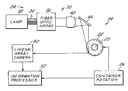
Apparatus for detecting checks in the sidewall of a translucent container (22) that includes a light source (24) for illuminating an elongated strip of the container sidewall parallel to the central axis of the container in such a way that illumination rays are incident at any point of the strip from multiple differing angles. A camera (50) is positioned externally of the container for receiving light reflected by checks in the illuminated strip, and electronic circuitry (52) is coupled to the camera for detecting checks in the container as a function of such reflected light. Since the light rays at any point in the elongated illuminated strip on the container sidewall are incident from multiple differing angles, planar checks and split seams in the container sidewall that are not precisely vertical in orientation will have a greater chance of reflecting light energy from the source onto the camera.


French Abstract

Appareil pour détecter des fissures dans la paroi latérale d'un contenant translucide (22) qui comprend une source de lumière (24) pour éclairer une partie allongée de la paroi latérale du contenant parallèlement à l'axe central du contenant de telle sorte que les rayons d'éclairage sont incidents à tout point de cette partie à partir de plusieurs angles différents. Une caméra (50) est positionnée à l'extérieur du contenant afin de recevoir la lumière réfléchie par les fissures situées dans la partie éclairée, et un circuit électronique (52) est couplé à la caméra pour détecter les fissures dans le contenant en fonction de cette lumière réfléchie. Les rayons lumineux en un point quelconque dans la partie lumineuse de la paroi latérale du contenant étant incidents à partir de plusieurs angles différents, les fissures planes et les soudures disjointes dans la paroi latérale du contenant qui ne sont pas précisément orientées verticalement auront une plus grande chance de réfléchir l'énergie lumineuse de la source sur la caméra.

Claims

Note: Claims are shown in the official language in which they were submitted.


Claims
1.
Apparatus for detecting checks and split seams in
a translucent container having a sidewall and a central axis
comprising:
a source of light for illuminating an elongated narrow
strip of the container sidewall parallel to the container axis,
a camera positioned externally of the container for receiving
light reflected by checks in the illuminated strip of the
container along a reflection axis perpendicular to the axis of
illumination from said light source, and means responsive to
said camera for detecting checks in the container as a function
of such reflected light,
characterized in that said source illuminates said
strip in such a way that illumination rays are incident at any
point of said strip from multiple angles essentially coplanar
with each other and with the strip, such that detection of non-
vertical radiant checks and split seams in the container sidewall
is improved.
2.
The apparatus set forth in claim 1 wherein said camera
comprises a linear array of light sensitive elements optically
parallel to the container axis.
-9-

3.
The apparatus set forth in claim 2 further comprising:
means for rotating the container about its central axis, and
means for scanning said linear array of light sensitive elements
at increments of container rotation.
4.
The apparatus set forth in any preceding claim wherein
said light source comprises a fiber-optic ribbon coupled at one
end to a source of illumination and disposed at a second end
to project said illumination onto said elongated strip of the
container sidewall.
5.
The apparatus set forth in claim 4 wherein said fiber-
optic ribbon at said second end forms essentially a linear array
of individual fiber-optics optically parallel to the container
axis.
6.
The apparatus set forth in claim 5 wherein said light
source further comprises a cylindrical lens for focusing light
from said fiber-optic ribbon in a direction perpendicular to
the container axis.
-10-

7.
The apparatus set forth in claim 5 wherein said fiber-
optic ribbon has a dimension parallel to the central axis of
the container at least as great as the dimension of the
illuminated strip of the container parallel to such axis.
8.
The apparatus set forth in claim 7 wherein said light
source further comprises mean for adjustably positioning said
light source with respect to the container and camera.
9.
A method of inspecting translucent containers
comprising the steps of:
(a) illuminating an elongated strip of the sidewall
of the container in such a way that illumination rays are
incident at any point within the strip at multiple angles,
(b) directing light energy reflected by checks in the
illuminated strip onto a photosensitive means, and
(c) detecting checks in the container sidewall as a
function of such reflected energy.
-11-

10.
The method set forth in claim 9 wherein said step (a)
is carried out by directing light energy onto said illuminated
strip through a fiber-optic bundle in which the individual
optical fibers are disposed in a linear array optically parallel
to the illuminated strip.
11.
The method set forth in claim 10 comprising the
additional step of:
(d) rotating the container about its central axis at
an orientation in which such axis is parallel to the illuminated
strip on the container sidewall.
-12-

Description

Note: Descriptions are shown in the official language in which they were submitted.


~~~~:~J~:~.
OT 16597
IIdSPECTIOId OF TRAHSLUCEpIT CONTAINERS
The present invention is directed to optical
inspection of translucent containers, and more specifically to
an apparatus and method for detecting so-called vertical checks
and split seams in the sidewalls of translucent containers.
Background and Objects of the Invention
In the manufacture of translucent containers such as
clear or colored glass bottles, various types of checks or other
commercial variations can occur in the sidewalls of the
containers. For example, variations known as split seams and
vertical checks may be present in the sidewall of a container.
These split seams and vertical checks are mirror-like reflective
cracks that lie in a plane and extend generally radially from
the longitudinal axis of the container. Many devices have been
proposed for detecting such variations.
U. S. Patent No. 4,584,469 discloses a device for
detecting split seams and vertical checks in the sidewall of a
glass container. A light source is positioned to one side of
the container to direct light energy onto the container wall

~~~~.~JL.i
from a direction perpendicular and lateral to the container
axis. The light source comprises an incandescent bulb and a
cylindrical lens for projecting an :image of the bulb filament
onto the container sidewall in an elongated narrow tightly
focused strip parallel to the container axis. A linear array
camera is positioned to receive an image of the illuminated
portion of the container from a direction perpendicular to the
illumination and container axes. As the container is held in
position and rotated about its axis, a radial planar check will
eventually be rotated into a position to reflect light from the
source to the detector. Thus, the vertical check or split seam
is detected as a bright spot on what is otherwise a normally
gray or dark background viewed by the detector. (Directional
terms such as "vertical°' assume vertical orientation of the
container axis with the mouth opening upwardly, as is typical
in the container inspection art.)
Although the device disclosed in the noted patent has
enjoyed substantial commercial success, further improvements
remain desirable. In particular, the device disclosed in the
noted patent is limited in its ability to detect checks that
are not precisely vertical and parallel to the container axis.
That is, if a check is non-vertical, light incident on the check
will be reflected by the check but not necessarily incident on
the camera. It is therefore a general object of the present
-2-

~~~~.~.li
invention to provide an apparatus and method of the general
character or type disclosed in the above-noted patent having
enhanced ability to detect and inspect non-vertical radial
checks and split seams in the container sidewall.
Summary of the Invention
Apparatus far detecting checks in the sidewall of a
translucent container in accordance with a presently preferred
embodiment of the invention includes a light source for
illuminating an elongated strip of the container sidewall
parallel to the central axis of the container in such a way
that illumination rays are incident at any point of the strip
from multiple differing angles. A camera is positioned
externally of the container for receiving light reflected by
checks in the illuminated strip, and electronic circuitry is
coupled to the camera for detecting checks in the container as
a function of such reflected light. Since the light rays at
any point in the elongated illuminated strip on the container
sidewall are incident from multiple differing angles, as
distinguished from substantially unidirectional illumination
in the above-noted patent, planar checks in the container
sidewall that are not precisely vertical in orientation will
have a greater chance of reflecting light energy from the source
onto the camera.
-3-

M ~ ~ ~ ~ ~ ,
In the preferred embodiment of the invention herein
disclosed, the light source comprises a fiber-optic ribbon
having ends disposed in an essentially linear array optically
parallel to the container axis, and a cylindrical lens disposed
between the fiber-optic ribbon array and the container for
focusing light from the array in a direction perpendicular to
the container axis to form the narrow elongated illumination
strip. In this way, the light rays incident on the container
sidewall are oriented at multiple angles essentially in a plane
parallel to the container axis. The fiber-optic ribbon has a
dimension parallel to the central axis of the container at least
as great as the longitudinal dimension of the illuminated strip.
The camera preferably comprises a linear array of light sensitive
elements optically parallel to the container axis and the
illuminated strip, with the camera array being scanned by
detection electronics at increments of container rotation.
Brief Description of the Drawings
The invention, together with additional objects,
features and advantages thereof, will be best understood from
the following description, the appended claims and the
accompanying drawings in which:
FIG. 1 is a functional block diagram of apparatus for
inspecting translucent containers in accordance with the present
invention;
_4_

CA 02132111 2003-O1-28
FIG. 2 is a schematic diagram of a portion of the
container and a portion of the light source in the apparatus
of FIG. 1;
FIG. 3 is an end elevational view of a portion of the ,
light source taken substantially along the line 3-3 in FIG'. 2;
FIG. 4 is a top plan view of a portion of the light
source illustrated in FIGS. 1-3; and
FIG. 5 is a fragmentary sectional view taken
substantially along the line 5-5 in FIG. 4.
Detailed Description of Preferred. embodiment
Referring to the drawings, a conveyor 20, typically
including a starwheel (not shown) and a slide plate 2l, is so
disposed and connected to a source"of molded containers as to
bring successive containers 22 into position at an inspection
station 24. Conveyor 20 may be of any suitable type, such as
those shown in U.S. Patent Nos. 4,230,219 and 4,378,493 as well
as above-noted U.S. Patent No. 4,584,469, and would typically
include a rotatable starwheel for bringing successive containers
into position and holding the containers in fixed position
during the scanning operation. A container rotating device 26,
such as a drive roller, is positioned to engage container 22
at station 24 and to rotate the container about its central
axis 23. An encoder or the like is coupled with the container
rotation mechanism to provide signals indicative of-increments
-5-

A
~~le~~j.~.l
of cantainer rotation. Alternatively, with the container
rotating at constant speed, increments of container rotation
may be inferred by increments of tine.
A light source 30 is positioned to one side of container
22 at station 24 for directing light energy on the container at
the station. Light source 30 comprises a lamp with power supply
32 connected by a fiber-optic bundle 34 to a fiber-optic array
36. As shown in FIG. 3, fiber-optic array 36 comprises a linear
essentially one-dimensional array of individual fiber-optic
elements 38. Preferably, fiber-optic cable 34 feeds into a
housing 40 in which the bundle is essentially fanned into a
plane that is essentially one fiber-optic element thick, with
the fiber-optic elements thereby terminating in the linear array
illustrated in FIG. 3. Fiber-optic array 36 preferably comprises
several hundred individual fiber-optic elements 38 fanned into
the planar array illustrated in FIG. 3. A cylindrical lens 42
is mounted by suitable bracketry 44 (FIGS. 4 and 5 > at a position
spaced from enclosure 40 of fiber-optic array 36. A mirror 46
is fastened to light source bracketry 44 at an angle to lens 42
for reflecting light energy from array 36 and lens 42 through
the sidewall of container 22, at which the light is focused to
a narrow vertical strip as previously described. A clamp 48
is fastened to light source bracketry 44 for vertically arid
angularly adjusting orientation of the assembly relative to the
container at inspection station 24.
-6--

CA 02132111 2003-O1-28
A linear array camera 50 (FIG.1) is positioned
relative to container 22 at station 24 for receiving light
energy from light source 30 reflected by checks in the
container sidewall. Camera 50 includes a linear array of
photosensitive elements oriented optically parallel to axis
23 of container 22 at inspection station 24. An
information processor 52 is coupled to linear array camera
50 and container rotation mechanism 26 for scanning the
elements of camera 50 at increments of container rotation,
and thereby receiving from the camera image data indicative
of any checks in the sidewall of container 22 that reflect
light from source 30 onto the camera. Linear array camera
50, information processor 52 and container rotation
mechanism 26 may be of the type disclosed in the above-
noted U.S. Patent No. 4,584,469. Alternatively, camera 50
may be an area array camera of the type disclosed in U.S.
Patent No. 5,200,801 assigned to the assignee hereof.
The ends of the individual fiber-optic elements 38
function in effect as individual light sources from which
light rays emerge and diverge toward cylindrical lens 42.
Lens 42 functions to focus the light rays in the direction
perpendicular to container axis 23, as illustrated in FIG.
1, but does not substantially affect or bend the path of
travel of the individual light rays parallel to
container axis 23. Thus, the light rays

_~ e9 ~ 1 ~ 1
from the individual fiber-optic element ends diverge and
intersect each other so that, when incident on the container
sidewall, they travel essentially in a tightly focused plane
parallel to the container axis, but intersect and illuminate
the container sidewall from multiple differing angles within
that plane. Thus, in FIG. 2, the overall vertical dimension of
the illumination beam is illustrated by the solid lines 60,
while the phantom lines 62 illustrate the angles of illumination
of a split seam 64 in the sidewall of container 22. Because of
the multiple differing angles at which the light is incident
on split seam 64, the likelihood of detecting split seam 64 at
camera 50 is greatly enhanced even if the split seam is not
oriented exactly or substantially parallel to container axis 23.
_g_

Representative Drawing
A single figure which represents the drawing illustrating the invention.
Administrative Status

2024-08-01:As part of the Next Generation Patents (NGP) transition, the Canadian Patents Database (CPD) now contains a more detailed Event History, which replicates the Event Log of our new back-office solution.

Please note that "Inactive:" events refers to events no longer in use in our new back-office solution.

For a clearer understanding of the status of the application/patent presented on this page, the site Disclaimer , as well as the definitions for Patent , Event History , Maintenance Fee  and Payment History  should be consulted.

Event History

Description Date
Inactive: Expired (new Act pat) 2014-09-15
Grant by Issuance 2003-11-18
Inactive: Cover page published 2003-11-17
Inactive: Final fee received 2003-08-26
Pre-grant 2003-08-26
Notice of Allowance is Issued 2003-03-24
Letter Sent 2003-03-24
Notice of Allowance is Issued 2003-03-24
Inactive: Approved for allowance (AFA) 2003-03-12
Amendment Received - Voluntary Amendment 2003-01-28
Inactive: S.30(2) Rules - Examiner requisition 2002-07-30
Amendment Received - Voluntary Amendment 2000-03-02
Inactive: Application prosecuted on TS as of Log entry date 1999-11-30
Letter Sent 1999-11-30
Inactive: Status info is complete as of Log entry date 1999-11-30
All Requirements for Examination Determined Compliant 1999-09-29
Request for Examination Requirements Determined Compliant 1999-09-29
Application Published (Open to Public Inspection) 1995-03-17

Abandonment History

There is no abandonment history.

Maintenance Fee

The last payment was received on 2003-07-08

Note : If the full payment has not been received on or before the date indicated, a further fee may be required which may be one of the following

  • the reinstatement fee;
  • the late payment fee; or
  • additional fee to reverse deemed expiry.

Patent fees are adjusted on the 1st of January every year. The amounts above are the current amounts if received by December 31 of the current year.
Please refer to the CIPO Patent Fees web page to see all current fee amounts.

Owners on Record

Note: Records showing the ownership history in alphabetical order.

Current Owners on Record
OWENS-BROCKWAY GLASS CONTAINER INC.
Past Owners on Record
JAMES A. RINGLIEN
TIMOTHY J. NICKS
Past Owners that do not appear in the "Owners on Record" listing will appear in other documentation within the application.
Documents

To view selected files, please enter reCAPTCHA code :


To view images, click a link in the Document Description column. To download the documents, select one or more checkboxes in the first column and then click the "Download Selected in PDF format (Zip Archive)" or the "Download Selected as Single PDF" button.

List of published and non-published patent-specific documents on the CPD .

If you have any difficulty accessing content, you can call the Client Service Centre at 1-866-997-1936 or send them an e-mail at CIPO Client Service Centre.


Document
Description 
Date
(yyyy-mm-dd) 
Number of pages   Size of Image (KB) 
Representative drawing 1998-05-27 1 10
Representative drawing 2002-08-07 1 10
Description 2003-01-27 8 238
Claims 2003-01-27 4 79
Abstract 1995-06-04 1 21
Drawings 1995-06-04 2 32
Claims 1995-06-04 4 123
Description 1995-06-04 8 322
Acknowledgement of Request for Examination 1999-11-29 1 178
Commissioner's Notice - Application Found Allowable 2003-03-23 1 160
Correspondence 2003-08-25 1 33
Fees 1996-06-25 1 92