Note: Descriptions are shown in the official language in which they were submitted.
2 1 3 2 1 4 ~
-- ADDITIONAL STRUCTURE FOR IMPROVING THE PRESSURE
DISTRIBUTION ON THE DISKS OF AN AIRCRAFT BRAKE
DESCRIPTION
The invention relates to an additional floating metal struc~ - `
ture for improving the pressure distribution on the disks of
an aircraft brake.
A conventional aircraft brake comprises a coaxial stack of
friction disks, which are called rotors and stators.
The rotors are rotated by the rim of the wheel, via a plura-
lity of pins located on the interior of the rim and parallel
lS to its axis. They can consequently slide with respect to the
rim.
By an identical principle, the stators are linked in rotation -~
with the wheel axle, whilst being able to slide with respect
to said axle.
The rotors and stators are stacked in an alternating manner
and it i8 merely necessary to axially compress the system for ~;
braklng to take place. This compression is brought about by j ,",r,"~.
a plurality of hydraulic ~acks arranged axially on a circum-
ference havlng a dlameter close to the mean dlameter of the
friction or rubblng faces of the dlsks. Thls plurallty of
Jacks is flxed to the wheel hub. Opposite to the stack of ~`
dlsks wlth respect to the Jacks are also fixed to the wheel ~ ~ ;
hub a certaln number of support points centred on the mean
dlameter of the rubbing faces of the disks. ; ;-~
,, ! . j ! ., . ' '~ . ,
In order to control friction, only half the number of ~acks
18 used, the other half serving as a standby, security system.
However, there 18 nothing to distinguish the two groups of
;~ ~acks,~which are also arranged in alternating manner on the
'~ clrcumference.
~ SP 8346.69 GP ;~ .
213214~ -
-- 2
In the prior art, the jacks bear directly on the face of the
first stack of the disk, which is always a stator becaus~ it
must not slide with respect to the ~acks.
. :~
The aim of this configuration is to gain weight. For the
same reason the number of ~acks arranged in circumferential
manner is as small as possible. For a commercial airliner
there are e.g. in general 10 to 14 jacks, i.e. 5 to 7 simult-
aneously active jacks.
'~ '" ' "' ''~' ' "
. .
Bearing in mind the diameter of the disks, the distance
between the active ~acks is consequently approximately 20 cm.
This distance is considerable compared with the thickness of
the disks, so that there is a very significant pressure varia-
tion between the disks as a function of the ~ack spacing.
When the disks are made from carbon and more particularly
good heat conducting carbon, so that they are not very hard,
this pressure heterogeneity is responsible for an increase
in wear. ;;-~
- ~ x
This pressure heterogeneity also leads to temperature hetero~
geneities and more partlcularly to very hot zones in the ~i i i
extension of the axis of the ~acks. As the friction coeffic- ~ i
ient of carbon and many frlction materials decreases greatly
25 with the temperature, there is a very signiflcant reduction ; ~ i
in-!the stopplng performance, particularly in the case of an
aborted take-off.
The ob~ect of the invention is to very significantly reduce
the pressure heterogeneity, whilst only adding a relatively
small mas!s or weight to~the already produced brake.
In a first embodiment of the invention is proposed a floating
metal structure interposable between the ends of the Jacks of
an aircraft brake and the disk closest to the brake with a ;
view to improving the distribution of pressure on the said .
disk and the following disks, characterized in that its i~
.,;, :- ~,. ... .
~ SP 8346.69 GP ~
213214~
- 3 -
general shape is circular and coaxial with the disks and in
that its radial section is a U with a flat base in which are
inserted with an adequate clearance and bear the ends of all
the ~acks, the ends of the sides of the U being extended
towards the exterior of the U so as ~o form two concentric
rings with a profile substantially parallel to the base of
the U.
This leads to a light, but very stiff floating metal struc-
ture.
This solution can be applied without other changes to exist~
ing brakes and it is original in the sense that it has the
form with the optimum stiffness and weight performance
characteristics bearing in mind the spaces available on all
existing brakes on either side of the end of the Jack~. The
circular structure can be produced from sheet metal or metal
machined in the mass. Its section along the circumference
thereof is that of a flat-bottomed U and having to the right
20 and left at the top of the U a segment parallel to the base. -
The sum of these segments is substantially equal to the
length of the flat base. However, this length arrangement i8 ~:
not imperative and variants can be envisaged, partlcularly
taklng account of the thicknesses of the various zones.
The helght of the U is equal to the dlstance separating the
~ack flxlng plate from the disk surface when the length of
the ~acks is a minimum. - ~;~
30 The sides of the U aire intended to surround!with a certaini ; `
operating clearance the base of all the ~acks.
The end of the ~acks is only separated from the first disk
by the thickness of the structure, which is negligible for
~i~ 35 the geometry of the brake.
SP 8346.69 GP
.,
2~321~6
- 4 -
For information purposes, a circular steel structure accor~
ding to the invention wéighing approximately 2 kg improves
significantly the pressure distribution on a brakP, because
its stiffness is equivalent to that of two of the thickest
disks for a system of 9 carbon disks weighing 50 kg. ;~
..
When this solution i~ adopted, it i5 preferable for the supp- . -
ort pads screwed to the end of the ~acks to be square or ~-
rectangular or, in the optimum case, in the form of a radial
ring sector in order to improve the transmission of forces to
the metal structure.
, " ~
In a second embodiment of the invention a floating metal ~ ;
structure is proposed, which can be interposed between the
ends of the Jacks of an aircraft brake and the disk closest
to the ~acks, with a view to improving the distribution of
pressure on said disk and on the following disks, character-
ized in that its face intended to come into contact with the - `
disk closest to the ~acks is provided with a number of shims
20 identical to the total number of Jacks, the shims being ~-,
centred on the bisector of the angle at the centre between
two ~acks as a result of angular marking means between the
metal structure and at least one of the Jacks.
25, This solution is complimentary to that given hereinbefore,
but according to the invention, it can optionally relate to
a structure inltially substantially different from that des-
cribed hereinbefore. -
It consists of fixing, e.g. by welding or soldering, thin
shims beneath the base of the U, i.e. between said base and
the first disk of the brake. These shims are arranged in
staggered manner with respect to the active and inactive
Jacks.
SP 8346.69 GP
'~;
21321~
If a brake has a total of 10 active and inac~ive ~acks there
are consequently 10 shims below the bottom of the U and each
of them is positioned between two Jacks.
~;
In thi~ case, the U structure is equipped with an angular
marking making it possible to position it angularly with res- ;~
pect to at least one ~ack. Thus, with said shims, the number
of support or bearing points is equal to the sum of the ~-~
active and inactive ~acks, i.e. it is twice that of the prior -
art situation. The behaviour of the brake is unchanged on
passing from the active to the inactive ~acks. ~ ;
~;:
The interest of this solution is that the deflection or sag
f of the disks responsible for the pressure heterogeneities
is in the following form~
f = K ExI
P - load per ~ack
L = distance between ~acks
E = modulus of elasticity in the plane
I - moment of inertia
K = a coefficlent dependent on the settlng lnto the supports
ant the load distrlbutlon type, lt being difficult to accur- ;
ately determlne, but remalns valld on a comparatlve basis.
Thus, with double the number of ~acks the deflection tends to
be elght tlmes lower~ This factor is a minimum because,
bearing in mind the dlameter of the Jacks, the free bearing
reduction takes place in a factor exceeding two.
The advanta~e of said second solution compared with the first
is therefore on the one hand being much more efficient for
the same weight and on the other is more independent of the ;;
stiffness of the ~ structure, so that the latter can be
lightened.
SP 8346.69 GP
: ~ "'''' ' ~',
- 6 - 2~3~
,. .
The sags or deflectlons attained under load in the case of : ; .
the above example are very small, so that very thin shims can
be used according to the invention. Their thickness is pref~
erably between the sag corresponding to the yield strength of
the metal from which the U structure is formed and the sag
corresponding to the maximum force applied in practice added
to the sag of the first disk.
Another possibility according to the invention consists of
observing that the practical application of the maximum load
is extremely rare and therefore has little effect on the wear. .
It i8 therefore possible to give the shims thicknesses such
that they ensure the most regular possible pressure dlstrib- :~;: .
ution during frequent braking operations at medium pressure
and that when in exceptional cases the pressure increases,
the clearance between the axis of the active pistons is can-
celled out between the flat bottom of the U structure and
the first disk of the stack.
Thus, the U structure is protected against the possibility
of undergoing significant deflections which could give it a
permanent deformation if its temperature was high at that
particular instant.
The dlmensions of the shims accordlng to the invention, other
than thelr thlckness, can vary relatlvely signlflcantly. :~
However, lt 18 logical that their width measured radlally
wlth respect to the disk 18 identical to that of the base of
the U. :
! ~::
The length thereof in the clrcumferentlal direction can - :
~; evolve under the following conditlons~
- if it is short, the principle of the invention is perfectly
: respected from a theoretical standpoint, because the bearing ~ :~
~'~ 35 points on the first disk are equidlstant;
SP 8346.69 GP
~ 7 ~ 2132~46 : ~
- if it increases, the bearing zone tends to approach the
active ~acks due to the deflection of the U structura.
However, if the U structure is relatively rigid, it can be of
interest to increase the circumferential length of the shims
in order to combine the advantages of the first and second
solutions according to the invention.
,",,
The U structure according to the invention also has the advan-
lO tage of providing a heat protection for the ~acks, as a ~;
result of the fact that they are no longer in direct contact
with the disks which heat. It is possible to use support
shims made from insulating and adequately refractory mater~
ials. For this purpose, with the shim thicknesses being very
small (approximately 0.05 to l mm), it is possible to envis-
age various solutions such as e.g.
- deposits of not very conductive ceramics or which are -~
sintered and with low density,
- use of relatively slightly conductive metals (stainless
steel, etc.),
- use of porous sintered metals. ; ~-;
-"
The U-shaped metal structure can also be made from slightly
conductive steel.
In the case wherq no use i9 made of shims, the thermal con-
tact 18 good between tbe first disk and the U-shaped metal ~ ;~
structure. This structure can then serve as a heat radiator ~;
during the ventilation of the brakes following a landing.
~The shape of the U structure gives it a large exchange!sur
face with the ambient air and can therefore be used for more ~ `
rapidly extracting the heat from the very compact disks.
When this ancillary use of the U structure is adopted, it is
possible according to the invention to furthér increase its ~ ;;
` ~ 35 efficlency by welding to it metal fins having a negligible ~
~ se a346.69 Ge ~ r~
- 8 - 2 1 3 2 1 ~
. .. ...
weight. Thus, the U structure can be used as a heat exchan-
ger or insulator. However, in all cases, this structure
thermally protects the ~acks.
The invention is described in greater detail hereinafter rela-
tive to non-limitative embodiments and the attacked drawings,
wherein show~
~ig. 1 A diagrammatic section of an aircraft disk brake.
Fig. 2 A diametrical sectional view illustrating a first
embodiment of the metal structure according to the
invention.
Fig. 3 An axial view of the metal structure of fig. 2
showing the support of one of the Jacks.
.. :. ; ~
Fig. 4 A radial sectional view of the metal structure of
figs. 2 and 3 through the axis of one of the Jacks.
~ A,,
Fig. 5 A developed view of a plurality of ~acks bearing `~
on the bottom of a metal structure shown in sec-
tlon, lllustratlng a second embodlment, in which
the support shlms and a system for angular posl-
tlonlng wlth respect to the Jacks are installed on
the structure.
. :.
Fig. 6 A radlal sectional view through the axls of a Jack
illustrating a variant of the metal structure, ln
whlch cooling fins ln the form of concentric rlngs
are lnstalled on the structure.
Fig. 1 shows the rotor disks 1 of an aircraft brake rotated
by pins 2 integral with the wheel rim 3, the tyre not being -~
35 shown. It is also possible to see the brake stator disks 4 -~
locked in rotation by the pins 5 integral with the wheel hub
6. The rotor 1 and stator 2 disks are arranged in alterna-
--~. . ,:: ~,
~SP 8346.69 GP
9 2 1 3 2 1 ~
ting manner in order to form a stack of disks. -~
A plurality of ~acks 7 is fixed to a ring 8 integral with the
hub 6 in front of one end of the stack. Moreover, the disks
5 are secured axially at the other end of the stlck by a
retaining ring 9 generally having a plurality of support or
bearing points 10. -~
According to the invention, a circular metal structure 11,
10 shown in figs. 2 and 3, is placed between the pistons of the
~acks 7 and the adjacent stator disk 4. This circular metal
structure has a U-shaped section with a flat base 13. The
sides 12a, 12b (fig. 4) of the U formed in section by the
metal structure 11 are extended towards the outside of the
15 U, parallel to the flat base 13, in the form of segments 14,
15, whereof the sum of the lengths is substantially equal to
that in section of the flat base 13. Moreover, each of the
segments 14, 15 has substantially the same length.
Fig. 3 shows that the segments 14 and 15 are in fact internal
14 and external 15 concentric rings. i~ ;~
.
Fig. 4 shows the position of the metal structure 11 with res-
pect to each of the ~acks 7. The wldth of the U formed ln
section by the structure 11, l.e. the dlstance between the
substantlally parallel sldes 12a, 12b, sllghtly exceeds the
dlameter of the cyllnder of the ~acks 7. Consequently, the
latter are placed between the sldes 12a, 12b ln such a way ~-~
that the metal structure 11 can sllde freely around the -~
cyllnder of the ~acks 7. ` ! i ;~ i~`,J, ,`
The ends of the pistons 16 of the ~acks 7 are equipped with
support pads 17 coming into contact with the base 13 of the
structure 11. These support pads 17 freely penetrate said
structure. Their function is in particular to centre the ; - ~
~,: , ,; "
", " :'.
SP 8346.69 GP
- lo - ~ ~3 2 ~
structure 11 relatlve to the axis of the brake. They are also;;;
used for transmitting the force to the structure 11 in an
.:.- :,,,,:
optimum manner and for this purpose it is preferable to ~ '
replace the conventional circular support pads by pads 17
having the shape of ring sectors, like that shown in fig. 5. ;~
The height of the U formed in section by ~he structure 11,
i.e. the helght of the sides 12a, 12b, i8 equal to the dis-
tance separating the ring 8 carrying the Jacks 7 from the
~urface of the first stator disk 4, when the Jacks are com-
pletely retracted. ,;
The metal structure 11 is made from a light, refractory metal -, `
with a high modulus of elasticity, beryllium being preferred.
15 It is also possible to use other metals such as steel. ~ ~ ~
The structure 11 is easily shaped by forging or machining, or ~;
e.g. the assembly of welded or riveted components. The
represented shape of the metal structure 11 can, according to
the invention, undergo numerous modifications more particu-
larly with respect to the local thicknesses, angles and prop-
ortions between the lengths of the various segments.
,
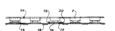
Flg. 5 shows the second embodlment of the lnventlon, in whlch
the support shlms 18 are posltloned between the first stator
dlsk 4 of the brake and the metal structure 11 and are fixed
to the latter.
It i8 possible to see a plurality of ~acks 7 located on the
30 same circumference,lshown in developed form in fig. 5 ,! as~-
well as the section of the structure 11 passing through the
axis of all the jacks 7. It is possible to see the shims 18
equidistant between ad~acent ~acks 7.
It should be noted that this principle of shims 18 is insep-
arable from an additional metal structure 11, but that the
,: . . , ~ ., .
S~ 8346.69 ~ ~
2132~ ~6
1 1 --
latter can have, according to the invention, a much less mech-
anically optimized shape than that forming the ob~ect of the
first embodiment.
Fig. 5 also shows two brackets 19, 20 for angularly marking
during installation the metal structure 11 with respect to
the Jacks 7, in such a way that the shims 18 are indeed mid-
dlstance from the ~acks. The brackets 19, 20 are formed on
the inner face of the flat base 13 of the structure 11 and
are separated by a distance slightly exceeding the circumfer-
ential length of the pads 17, so that they are placed on
either side of one of them.
It ~hould be noted that the brackets 19, 20 are in no way
limitative with respect to the invention and numerous other
means can be used for permitting the angular positioning of
the metal structure 11.
~ig. 6 shows a variant in which the metal structure 11 is
equipped with a heat exchanger constituted by fins 19, which
are spaced, superimpoæed concentric rings fixed to the sides
12a, 12b by any means ensuring a good thermal contact, e.g.
welding.
A~ a varlant and whilst occupylng the same location as the
ring fins 19 in fig. 6, the flns can also be located in ;;~
planes passing through the axis of the structure 11, or in
the form of coaxial cylinders fixed to the inner 14 and outer -~
15 rlngs.
~, ''~. .-,'.'. ''..',
~ '., ~ ,;'."``'"'""'
" ` " " `"''
SP 8346.69 GP