Note: Descriptions are shown in the official language in which they were submitted.
VARIABLE CAPACITY VANE COMPRESSOR
WITH AXIAL PRESSURE DEVICE
._
2 BACKGROUND OF T~E INVENTION 213 217 ~
3 1. Field of the invention:
This lnvention relates in general to variable
6 capacity vane compressors for air conditioning systems,
7 particularly for vehicles, and in particular to an
8 axial pressure device that enhances sealing between a
9 rotary valve plate and a compression housing shoulder.
11 2. Description of the Prior Art:
12
13 One type of automotive air conditioning compressor
1~ in use is a variable capacity vane compressor. In this
type of compressor, a compression housing has a chamber
16 that is oval in shape. A cylindrical rotor extends
17 through the chamber. The rotor has radial vanes mounted
18 to it which slide radially in slots formed in the rotor.
19 Refrigerant at suction pressure enters the compression
chamber, with the vanes compressing the refrigerant,
21 which passes outward through a valve.
22 The compressor demand varies according to speed and
23 atmosphere conditions. At highway speed, the demand is
2~ usually lower than while idling on a hot day. To vary
the capacity, a rotary valve disk or plate mounts in
26 front of the compression housing and in engagement with
27 a shoulder on the compression housing. The valve plate
28 has a slotted perimeter which will change the position of
29 the opening from the intake chamber into the compression
chamber depending upon the rotational position of the
31 valve plate. The valve plate is rotatably carried in a
32 rotary valve housing, also known as a rear side block.
2 ~
2132173
~ The particular rotational position of the valve plate
2 will change the quantity of refrigerant introduced
3 between the vanes for compression by changing the timing
4 of the compression cycle.
An actuator will rotate the valve plate to selected
6 -~positions depending~~upon the changes in the discharge
7 pressure and the intake or suction pressure. In one
8 type, such as shown in U.S. Patent 5,145,327, the
9 actuator mem~er comprises radial projections mounted to
the rear side of the rotary valve plate and located
11 within chambers. Each projection serves as a piston.
12 Variable fluid pressure is applied to both sides of each
13 piston. Also, a spring will urge the plate to a minimum
14 delivery position.
lS A control valve supplies a control pressure to one
16 side of each piston, the other side of each piston being
17 at intake pressure. The control valve includes a bellows
18 which has a stem that engages a ball valve. The bellows
~9 is located in a portion of the suction chamber. A
plunger or bias pin on the opposite side of the ball has
21 one end exposed to discharge pressure. The plunger and
22 the stem of the bellows cooperate depending upon the
23 discharge and intake pressure to selectively apply a
24 control pressure to one side of the pisto`ns for moving
the rotary valve plate.
26 In another type of actuator, the rotary valve plate
27 is rotated by a spool piston, such as shown in U.S.
28 Patent 4,838,740. The spool piston moves linearly
29 transverse to the axis of the rotor. The spool piston
has a pivot pin that engages the plate to cause it to
3~ rotate as the spool piston moves. Patents exist which
32 disclose a variety of control valves for applying
-
2132173
l pressure to the spool piston to cause it to move in
2 response to intake and discharge pressure.
3 Whether the actuator is a linear piston or a radial
~ projection, the rotary valve plate slidingly engages a
~-~ 5 shoulder facing rearward on the compression housing. The
-6~ -shoulder surrounds the compression chamber. The valve
7 plate slidingly engages this shoulder as the valve plate
8 rotates. Because the valve plate forms one end of the
9 compression chamber, it is important to have as good a
sealing as possible between the rotary valve plate and
11 the compression shoulder. In the type of rotary valve
12 plate wherein the actuatinq pistons are radially oriented
13 projections mounted to the rear side and radially
1~ oriented, variable axial pressure is applied to the
rotary valve plate because the rear side of the rotary
16 valve plate is exposed to the chambers containing control
17 pressure for rotating the valve plate. These chambers
18 cause a forward acting axial force to assist in sealing
19 between the face of the valve plate and the compression
shoulder.
21 On the other hand, in the type utilizing a linearly
22 movable spool piston, there is no axial pressure applied
23 to the rear side of the rotary valve plate. Consequently,
2~ there would be a tendency for leakage to occur between
the rotary valve plate and the compression shoulder. If
26 installed very tightly, leakage could be minimized,
27 however friction might make it difficult to rotate the
28 rotary valve plate.
-
213217~
1 SUMMARY OF THE INVENTION
3 In this invention, the actuator is a spool piston
type. It is located transverse to the axis of the rotor.
A control valve supplies a control pressure to the
- 6 ~ actuator--to cause it-to move to-rotate the valve plate.
7 The rotary valve plate is located in a rotary valve
8 housing, which also contains the chambers for the spool
9 type actuator piston.
An annular axial pressure chamber is located between
11 the rotary valve housing and the rotary valve plate. A
12 control pressure port leads from the control valve to the
13 axial pressure chamber to supply pressurized fluid to the
1~ axial pressure chamber. This pressurized fluid varies
depending upon the demand on the compressor, and
16 therefore provides a variable axial force on the rotary
17 valve plate. This enhances sealing between the rotary
18 valve face and the compression housing shoulder.
19 In the preferred embodiment, the axial pressure
chamber is located in the rotary valve housing. An
21 annular elastomeric seal locates in the axial pressure
22 chamber. An annular bearing locates on the rotary valve
23 plate in engagement with the seal. Control pressure
24 supplied to the seal will cause the seal to exert an
axial force on the bearing, which transmits to the rotary
26 valve plate. The bearing allows rotation of the rotary
27 valve plate while the seal remains stationary.
- 2132173
1 BRIEF DESCRIPTION OF THE DRAWINGS
3 Figure 1 is a partial sectional view illustrating a
4 compressor constructed in accordance with this invention.
6 Figure 2 is another sectional view of the compressor
7 of Figure 1, taken along a line perpendicular to section
8 line 2-2 of Figure 1.
Figure 3 is a partial sectional view of the compressor
11 of Figure 1, taken along section line 3-3 of Figure 2.
12
13 Figure 4 is another partial sectional view of the
14 compressor of Figure 1, taken along a section line 4-4 of
Figure 3 and with a portion of the rear head shown in
16 section.
17
18 Figure 5 is a sectional view of the compressor of
19 Figure 1, taken along the line V-V of Figure 1.
21 Figure 6 is a rear elevational view of the rotary
22 valve plate used with the compressor of Figure 1.
23
24 Figure 7 is another sectional view of the compressor
of Figure 1 with the discharge chamber shown.
, ~e
. . .
21~2173
2 DETAILED DESCRIPTION OF THE INVENTION
4 Referring to Figure 1, compressor 11 is shown partly
in a sectional view. Compressor 11 is a variable capacity
6 vane type compressor. It includes a compressor housing 13
7 which has compression chamber 15. As shown in Figure 5,
8 compression chamber 15 is generally oval in configuration.
9 A plurality of vanes 17 mounted in slots on a rotor 19
rotate inside compression chamber 15. Rotor 19 rotates on
11 an axis 21 that is concentric with compression chamber 15.
12 Valves 23 (only one shown) provide for the discharge of
13 refrigerant gas from the compression chamber 15. The
14 refrigerant gas passes to a discharge chamber, which is not
shown, but which is the type as shown in U.S. Patent
16 5,145,327, Nakajima, et al, September 8, 1992.
17 Referring again to Figure 1, a rotary valve plate 25
18 mounts rotationally to the intake side of compressor
19 chamber 15. Rotary valve plate 25 is a disk-shaped member,having an irregular perimeter 27 as shown in Figure 6,
21 which defines slots. As shown by the dotted lines in
22 Figure 5, the particular rotational position of rotary
23 valve plate 25 will change the position of the intake
24 opening into the compression chamber 15 and thus the volume
of refrigerant introduced between the vanes 17 as rotor 19
26 rotates. In this manner, the capacity of compressor 11 can27 be varied.
28 Referring again to Figure 1, rotary valve plate 25 has
29 a face 29 on the forward side that slidingly engages a
compression housing shoulder 31. The compression housing
31 shoulder 31 surrounds compression chamber 15.
.
-
2132173
1 The contact is metal-to-metal between rotary valve face
2 29 and compression housing shoulder 31.
3 Rotary valve plate-25 will rotate approximately 70
~ degrees from a fully closed position to a fully open
S position. Rotary valve plate 25 is carried in a rotary
- -~ 6 ~ ~valve housing 33,~also called a rear side block. Rotary
7 valve housing 33 mounts stationarily to compression
8 housing 13 and has a central portion 33a. A rear head 35
9 mounts to the rear of rotary valve housing 33 by bolts.
An intake chamber 37 is defined within rear head 35 and
11 surrounds the central portion 33a of rotary valve housing
12 33. Intake chamber 37 will be at the suction or intake
13 pressure of the refrigerant after it has passed through
14 the evaporator tnot shown).
An actuator member or piston 39 will rotate rotary
16 valve housing 33 between the minimum and maximum
17 positions. Actuator piston 39 is a spool-type piston,
18 located transverse to the axis 21 of rotor 19. As shown
19 in Figure 2, actuator piston 39 is located in a piston
chamber 41 which extends transversely through rotary
21 valve housing 33. The central portion of piston chamber
22 41 is intersected by a portion of intake chamber 37, thus
23 resulting in two separate sections. Actuator piston 39
24 has a seal 42 which defines in chamber 41 a suction side
41a, which is on the right side of seal 42, and a control
26 pressure side 41b, which is on the left side of seal 42.
27 Control pressure side 41b is supplied with a control
28 pressure for moving actuator piston 39 to the right in
29 response to change in demand on compressor 11. A coil
spring 43 urges actuator piston 39 to the left, which
31 positions ro~ary valve plate 25 in the minimum capacity
32 position. End caps 45, 47 seal the opposite ends of
2132173
1 piston chamber 41. A suction passage (not shown) extends
2 from the intake chamber 37 to the suction side 41a to
3 assure that suction pressure is communicated to the
~ suction side 41a of piston chamber 41.
- 5 Referring to Figures 1 and 3, the linkage means
6~ bet-ween--actua`tor-piston 39 and rotary valve plate 25
7 includes in the preferred embodiment a roller 51, which
8 is a small, slidable member locating within an undercut
9 52 in actuator piston 39. Roller 51 is rotatably
supported on a pin boss 53, which is rigidly mounted to
11 rotary valve plate 25. Linear movement of actuator
12 piston 39 causes rotational movement of rotary valve
13 plate 25 through roller 51 and pin boss 53.
1~ Referring again to Figure 1, axial piston means
exist for applying a variable axial force on rotary valve
16 plate 25 to enhance sealing between rotary valve face 29
17 and compression housing shoulder 31. The axial piston
18 means includes an annular axial pressure chamber 55 that
19 is located in central portion 33a of rotary valve housing
33. Axial pressure chamber 55 is a groove concentric to
21 rotor axis 21. Axial pressure chamber 55 is rectangular
22 in transverse cross section. Control pressure will be
23 supplied to axial pressure chamber 55, as will be
2~ explained subsequently.
The axial piston means also includes a seal member
26 or seal ring 57, which is sealingly located in axial
27 pressure chamber 55. Seal ring 57 is a conventional O-
28 ring, circular in transverse cross section. Seal ring 57
29 will have its rearward side exposed to control pressure
in axial pressure chamber s5. An annular bearing 59 is
3' located on a shoulder 61 on rotary valve plate 25.
32 Bearing 59 is a conventional thrust bearing which has one
2132173
r- side engaged by seal ring 57 and the other side in contact
2 with shoulder 61. In the preferred embodiment, bearing 59
3 is a needle-type thrust bearing, with needles located
4 between forward and rearward plates. The forward plate,
which is in contact with shoulder 61, will rotate with
6 rotary valve plate 25, while the rearward plate of bearing
7 59 will remain in stationary engagement with seal ring 57.
8 Seal ring 57 can move axially within axial pressure chamber
9 55 to exert a variable axial force on bearing 59 to
increase and decrease the force of rotary valve face 29 on
11 compression housing shoulder 31.
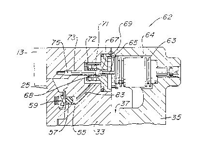
12 A control valve 62 for supplying control pressure to
13 actuator piston 39 and to axial pressure chamber 55 is
14 shown in Figure 4, and partially in Figure 3. Control
valve 62 does not appear in Figure 1 because of the
16 different sectional view shown in Figure 1. Control valve
17 62 appears only partially in Figure 3, because the rear
18 head 35 is not shown in Figure 3. Control valve 62
19 includes a bellows 63 which is initially evacuated and
mounts within a cavity 64 in the rear head 35. Cavity 64
21 is in communication with intake chamber 37, thus the
22 exterior of bellows 63 is in communication with intake
23 chamber 37. Bellows 63 has a stem 65 that extends parallel
24 to the rotor axis 21 (Fig. 1). Stem 65 will move forward
and rearward due to expansion and contraction of bellows
26 63.
27 Stem 65 engages a ball 67 which is located in a ball
28 seat member 69 and urged by a spring 68 to a closed
29 position. Ball seat member 69 is located in rotary valve
housing 33. Lateral holes 71 extend outward from ball seat
31 member 69 to allow the discharge of fluid into control
32 chamber 72 in rotary valve housing 33. A bias pin or
33 plunger 73 slidably moves within a plunger passage 75.
34 Bias pin 73 is coaxial with stem 65 and engages the
?
2132173
1 opposite side of ball 67. If bellows 63 expands, stem 65
2 pushes ball 67 to the left off the seat of seat member
3 69, and pushing bias pin 73 to the left. Ball 67 then is
in an open position to allow flow of fluid from control
chamber 72,---through lateral holes 71, and into the
6 suction chamber~37. Conversely, if bellows-63 contracts,
7 spring 68 pushes ball 67 back into the seat of seat
8 member 69, blocking communication between suction chamber
9 37 and control chamber 72.
As shown in Figure 3, discharge pressure from the
11 discharge chamber (not shown) of compressor 11, is
12 applied through a passage 77 to the base of plunger
13 passage 75. The pressure thus acts on the left end of
1~ bias pin 73, urging bias pin 73 toward ball 67. A
lS metered orifice 79 extends from passage 77 to control
16 chamber 72. Metered orifice 79 is a small diameter
17 drilled hole to allow a continuous selected flow rate of
18 discharge pressure refrigerant to pass into control
~9 chamber 72. A control pressure passage 81 leads to
control pressure side 41b of piston chamber 41. Passages
21 77, 79 and 81 do not appear in Figure 4 because of the
22 different sectional view. Also, bellows 63 is not shown
23 in Figure 3 for simplicity.
2~ Referring again to Figure 4, a control pressure port
83 leads from control pressure chamber 72 to the axial
26 pressure chamber S5. Control pressure port 83 provides
27 a supply of refrigerant at the control pressure in
28 control chamber 72 to the seal ring 57. Pressure port 83
29 thus serves as part of a passage means for supplying a
variable control pressure to seal ring 57.
31 At startup, the actuator piston 39 will be located
32 in the position shown in Figure 2. Rotary valve plate 25
21~2173
1 will be in the minimum delivery position. Referring to
2 Figures 3 and 4, initially the bellows 63 will be
3 contracted and the force of discharge pressure on the end
of bias pin 73 plus the force of spring 68 on ball 67
will keep ball 67 closed. Discharge pressure from
- 6 passage 77 is applied to bias pin 73 and also flows
7 through metered orifice 79 into control chamber 72, and
8 through control pressure passage 81 to the control
9 pressure side 41b of actuator piston chamber 41. This
causes piston 41 to move to the right from the position
11 shown in Figure 2, rotating rotary valve plate 25. This
12 increases the capacity of compressor 11 by changing the
~3 timing of the compression cycle and increasing the volume
1~ of refrigerant being compressed.
15At the same time, discharge pressure is applied
16 through control pressure port 83 to seal ring 57, which
17 applies an axial force to rotary valve plate 25. This
18 causes rotary valve plate 25 to more tightly bear against
19 compression housing shoulder 31. Consequently, at high
pressures within compression chamber lS, a high axial
21 force proportional to the discharge pressure is applied
22 against the rotary valve plate 25 to enhance sealing with
23 compression housin~ shoulder 31.
2~At highway speeds and at cooler conditions, the
demand will decrease on compressor 11. The discharge
26 pressure and the suction pressure in suction chamber 37
27 will decrease. The lower suction pressure causes
28 bellows 63 to expand. When the force due to the
29 expansion of bellows 63 exceeds the force due to spring
68 plus the force due to discharge pressure acting on
~1bias pin 73, stem 65 will push ball 67 off of its seat.
32 This exposes control chamber 72 to pressure in suction
12
2132173
1 chamber 37. Some of the pressure can then bleed through
2 passage 81 (Fig. 3), control chamber 72, lateral holes 71
3 into the suction chamber 37. This decreases the force on
actuator piston 39, causing it to move to the left to
~ 5 rotate valve plate 25, reducing the capacity of
~-~~~~=~~~~~~~ 6~ - compressor~11.~ ~~ ~~~ ~~~~~~~~
7 At the same time, the lower pressure in control
8 chamber 72 is applied through control pressure port 83 to
9 the axial pressure chamber 55. The reduced pressure on
seal ring 57 reduces the axial force on rotary valve
11 plate 25. This allows rotary valve plate 25 to more
12 freely rotate back to a lesser capacity position.
13 Consequently, the axial force in rotary valve plate 25
1~ varies in proportion to the control pressure applied to
actuator piston 39.
16 This invention has significant advantages. Applying
17 an axial force to the rotary valve plate enhances sealing
18 between the rotary valve face and the compression housing
19 shoulder. Varying the force in response to demand of the
compressor avoids applying too much force when the valve
21 needs to rotate to a new position.
22 While the invention has been shown in only one of
23 its forms, it should be apparent to those skilled in the
2~ art that it is not so limited, but is susceptible to
various changes without departing from the scope of the
26 invention.
27