Language selection

Search

Patent 2132231 Summary

Third-party information liability

Some of the information on this Web page has been provided by external sources. The Government of Canada is not responsible for the accuracy, reliability or currency of the information supplied by external sources. Users wishing to rely upon this information should consult directly with the source of the information. Content provided by external sources is not subject to official languages, privacy and accessibility requirements.

Claims and Abstract availability

Any discrepancies in the text and image of the Claims and Abstract are due to differing posting times. Text of the Claims and Abstract are posted:

  • At the time the application is open to public inspection;
  • At the time of issue of the patent (grant).
(12) Patent Application: (11) CA 2132231
(54) English Title: METHOD OF MANUFACTURING SHEET-STEEL BLANKS
(54) French Title: METHODE SERVANT A FABRIQUER DES FLANS DE TOLE D'ACIER
Status: Deemed Abandoned and Beyond the Period of Reinstatement - Pending Response to Notice of Disregarded Communication
Bibliographic Data
(51) International Patent Classification (IPC):
  • B21C 37/02 (2006.01)
  • B23K 33/00 (2006.01)
  • B23P 15/00 (2006.01)
(72) Inventors :
  • TENHAVEN, ULRICH (Germany)
(73) Owners :
  • ULRICH TENHAVEN
(71) Applicants :
(74) Agent: KIRBY EADES GALE BAKER
(74) Associate agent:
(45) Issued:
(22) Filed Date: 1994-09-16
(41) Open to Public Inspection: 1995-04-08
Examination requested: 1994-11-29
Availability of licence: N/A
Dedicated to the Public: N/A
(25) Language of filing: English

Patent Cooperation Treaty (PCT): No

(30) Application Priority Data:
Application No. Country/Territory Date
P 43 34 199.3 (Germany) 1993-10-07

Abstracts

English Abstract


Abstract
A method of manufacturing sheet-steel blanks from much longer
slabs removed from strip. The longitudinal edges of the slabs
are trimmed straight and welded together and the blanks are cut
out of the edge-welded slabs. The longitudinal edges of two
slabs as long as 4000 mm are brought together and continuously
trimmed simultaneously over their total length.
- 6 -


Claims

Note: Claims are shown in the official language in which they were submitted.

Claims
1. A method for producing sheet-steel blanks comprising
the steps of: supplying a strip of sheet-steel; removing
slabs from said strip of sheet-steel, said slabs having a
length exceeding substantially the lengths of said blanks;
trimming straight longitudinal edges of said slabs; welding
together trimmed longitudinal edges of said slabs; cutting out
said blanks from the welded-together slabs, longitudinal edges
of two slabs as long as 4000 mm being brought together and
continuously trimmed simultaneously over their total length.
2, A method as defined in claim 1, wherein the
longitudinal edges of said two slabs abut while being trimmed.
3. A method as defined in claim 1, wherein the
longitudinal edges of said two slabs overlap while being trimmed.
- 5 -

Description

Note: Descriptions are shown in the official language in which they were submitted.


- 213~23~
1 METHOD OF MANUF~CTU~XN~; SHEET-S~EEL BLANKS
2 The present inventlon concarns a method of manufacturing ~heet~
3 stQel blank~ a~ reclted ln the preamble to Clalm 1.
Blank~ of thi~ typ2 c~n be emplo~ed to produce 3tamped or bent
6 component~ for automobile bodle~ for example. German Patent 4
7 235 110 describQ~ how they can belmanufactured strong enough to
8 stand up to the 3tra~sQ~ they wlll encounter.
Slab~ up to 30 times a~ long a~ the final blank~ are cut from
11 steel s~rlp. ~he ~l~b~ are trimmed ~traight along ~he edge~
12 with a 31~b ~hearer for example. ~he trimmed ~lab~ are
13 forward~d to welding apparatu~ and wolded together along the
14 longitudinal edges. The welded-together ~lab# ars introduced
lnto a stamping press and blank~ of the desired shape cut out
16 of them wlth appropriat~ dies.
17 :~ :
18 The advant~ge of ~uch a method la that trimming the edge~ of
19 the ~lab~ wlth the ~l~b 0hear0r ~or example improves edge-to- ; :
edge tlghtness for butt welding wlth a laser or electron beam :::
21 and overlap flt for ~queeze-~eam welding.
22
23 Thl~ advantage, however, is attainable only with shearers of
24 conventlonal ~ize, which c~n make cuts of up to only about 4000
mm. Wh~n much longer slab~ need to be welded together along -`
26 the longitudlnal ~dges, the expenditures involved in producing
27 dlmonslonally stable dies and ad~u~ting them to cut ~traight
,

21 32231
1 edge~ with as llttle burr ~ po~lble increa~e out of
2 proportlon, and thl~ particular ~tage in the method become~
3 problematic.
The ob~ect of the pre~nt lnventio~ accordingly an improved
6 and ~i~ple method of th~ a~ore~ald genu~ that can al30 be
7 employed to manu~acture ~heet-~teel blank~ definitely longer
8 than 4000 ~m and with stralght longi~udin~l edges.
., .
This ob~ct i8 ~t~lned ~3 reclted in ~he body of Claim 1.
11
12 Advantageou~ ~ltern~tlve ~nd adv~nced ver~ion~ of the method in
13 accordance wlth the pre~ant lnvention are reclted in Claim~ 2
14 and 3.
16 The method ln accordance with the pre~ent invention can also be
17 employed to ~dvantage to ~bt~in parallel edgae that dlverge
18 from the ntraight by varying how the sheet travel~ through the
19 devlce to an~uro that the longitudinal sdges of the slabs are
in contact before any cutting occurs.
21
22 Another e~senti~l advantag~ of the method i~ that, ~lnce sheet-
23 8te91 slab~ of any de~i~ed length can be cut, ~he length of the
24 ~labs can alway~ be optimally adapted to the length of the
blank as well a3 to ~hipp~ng and warehou~ing conditions.
26 ~he method ln accordance with the present invention will now be
27 ~pecifi~d wlth ref~rence to the accompanying schematic drawing.
-- 2 --

~y~
2~3223~
,
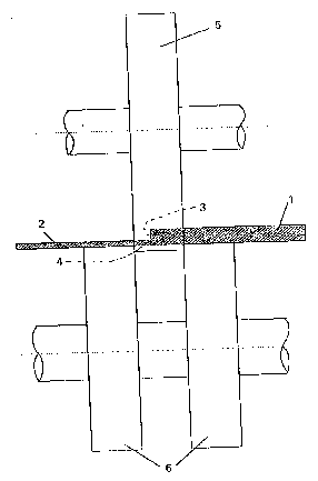
Flgure 1 illuE~rates one ver~loll of the method by way of a
2 ~ection through the ~he~t-~teel slab~,
4 Figu:re 2 illu~tratea the same ver~ion in per~pectl~e,
6 Figure 3 ~llu~tr~te~ ~notllq~r ver310n o~ the method by way of a
7 ~action through the ~l~b~, ~nd
9 Figura 4 illu~tr~te~ ~tlll ~nothex varsion of the method by way
o~ a ~ec~lon throuyh the ~lab~.
1 1
12 Sheet-steel slab are cu~ from appropria~e strips. The ~lab~ ~:
13 ar~ longer, 30 time~ a~ long ~or instance, than the final
14 blank~ will be evlderlt rom Figure~ 1 ancl 2, ~lab~ 1 and ~ :
2 ara po~itioned with their longitudinal edgas 3 and 4 together ~:
16 and advanced through an un~llustrated dovice that accommodates -:
17 a cutter. The cutter compri~e~ rotatlng circular blade~
18 specifically upp~r blade 5 and lowor blad~q 6. Blade~ S and 6
l9 trlm a narrow strip from sl~b~ 1 and 2 over their total length.
2~ ~`
21 The g~p between any two ~d~acent point~ ~long the trimmad and .;~
22 ready-to-weld longltudinal edges 3 and 4 will preclsely equal
23 tha thlcknes~ of upper blad~ 5 or the di~tanca between lower ~
24 blade~ 6. . ~ .
~5
26 ~lgure 3 illu~tr~e~ another version of the method in
27 accordance wi~h th~ pre~ent invention wherein 31ab~ 1 and 2
`~
- 3 - ~

2~3223~
1 ~dYance wi~h the?ir longltudlnal edge~? 3 ~nd 4 overlapping
2 through a device aecommodating a cutter that comprise?P.? rotating
3 circular blades, speclfically an upper blade 5 and a lower
4 blade 6, which trim a n~rrow strip from each overlapping slab
1 and 2 OV8r ~helr total length ln a single operatiQn.
7 ~?he trimmsd longitudinal edges 3 and 4 will accordingly be
8 hlghly p~rallel.
Flgure 4- illustr~tas anoth~r ver~?ion of the method in
11 accordance wlth the present lnventlon. Slabs 1 and 2 are
12 forced with their lonyitudinal edgQs i and 4 toge~h~r down
13 again~t p~ral 1Q1 and ~?tationary straight lower blade~ 7 by
14 appropria~e ~?Uppre~80r~?? 8 &O tlght that the edges are elevated
only a f~w millimaters above the edge~ 9 and 10 of lower blades
16 7-
17
18 A rotating clrcular upper blade 5 a? thick a~ the di&tance19 between &traight low?~r blade~? 7 deE?cend~ to between them and
roll~ along them, removing a strip 11 as wide as the overlap
21 ~?rom aach longitud~nal edge 3 ~nd 4.
22
23
24
27 .
-- 4 --
~. , . . .. , ~, ` .. '?'. .,

Representative Drawing
A single figure which represents the drawing illustrating the invention.
Administrative Status

2024-08-01:As part of the Next Generation Patents (NGP) transition, the Canadian Patents Database (CPD) now contains a more detailed Event History, which replicates the Event Log of our new back-office solution.

Please note that "Inactive:" events refers to events no longer in use in our new back-office solution.

For a clearer understanding of the status of the application/patent presented on this page, the site Disclaimer , as well as the definitions for Patent , Event History , Maintenance Fee  and Payment History  should be consulted.

Event History

Description Date
Inactive: IPC from MCD 2006-03-11
Time Limit for Reversal Expired 1997-09-16
Application Not Reinstated by Deadline 1997-09-16
Deemed Abandoned - Failure to Respond to Maintenance Fee Notice 1996-09-16
Application Published (Open to Public Inspection) 1995-04-08
All Requirements for Examination Determined Compliant 1994-11-29
Request for Examination Requirements Determined Compliant 1994-11-29

Abandonment History

Abandonment Date Reason Reinstatement Date
1996-09-16
Owners on Record

Note: Records showing the ownership history in alphabetical order.

Current Owners on Record
ULRICH TENHAVEN
Past Owners on Record
None
Past Owners that do not appear in the "Owners on Record" listing will appear in other documentation within the application.
Documents

To view selected files, please enter reCAPTCHA code :


To view images, click a link in the Document Description column. To download the documents, select one or more checkboxes in the first column and then click the "Download Selected in PDF format (Zip Archive)" or the "Download Selected as Single PDF" button.

List of published and non-published patent-specific documents on the CPD .

If you have any difficulty accessing content, you can call the Client Service Centre at 1-866-997-1936 or send them an e-mail at CIPO Client Service Centre.


Document
Description 
Date
(yyyy-mm-dd) 
Number of pages   Size of Image (KB) 
Drawings 1995-04-07 4 313
Abstract 1995-04-07 1 54
Claims 1995-04-07 1 66
Descriptions 1995-04-07 4 292
Representative drawing 1998-06-01 1 11
Prosecution correspondence 1994-11-28 1 35
Prosecution correspondence 1994-11-28 1 30
Courtesy - Office Letter 1995-04-25 1 33