Note: Descriptions are shown in the official language in which they were submitted.
21322~7
LINE TEN8IONER
Back~round of the Invention
The present invention relates generally to devices for
producing tension in a line. More particularly, the
present invention relates to line tensioners used with
adjustable length straps which are useful, for example, in
securing a cargo object in place.
The invention is particularly applicable to adjustable
length stretchable flexible cargo straps, sometimes known
as bungee cords, which are particularly useful for
retaining a load in place on, e.g., a vehicle. However, it
should be appreciated by those of average skill in the art
that the invention has broader applications and may also be
adapted for use in many other environments where it is
desired to tighten cable, rope, webbing or the like, such
as, e.g., tightening a tent rope, a guy wire, a sailing
line and so on.
Line tightener and snubbing devices for use with guy
ropes and the like permit the effective shortening of a
rope to take out the slack and secure it in the tightened
position. Prior devices, while they provided for the
tightening action and the prevention of slippage, were
rather difficult to adjust because of the frictional action
of the rope in passing through the device. Also, the known
devices of this sort are not simple and inexpensive to
manufacture, nor are they easy to use and most of them have
several movable parts.
Several types of stretchable flexible cargo straps are
known. Light duty cargo straps have been used to hold
small articles in place on, e.g. the luggage carriers of
bicycles. Medium duty cargo straps have been used to
secure luggage, sailboards, skis, lumber, ladders, pipes
and the like to cartop carriers or racks on pickup trucks.
Heavy duty straps have been employed to secure aircraft to
the decks of aircraft carriers. Typically, an attachment
2132~6~
means, such as a hook is provided at each end of such
flexible cargo straps.
The known stretchable cargo straps have, been the
subject of several limitations including, for example, a
breakage of the strap. Perhaps the most important
limitation of known cargo straps is that it is difficult to
maintain the desired amount of tensioning force on the
strap. Normally, a stretchable support strap has a given
free length or unstretched length. For use, such a strap
needs to be stretched to near its maximum "stretchable
length" so as to provide an effective tension force to hold
a cargo in place. Obviously, the strap should not be
stretched past its maximum stretchable length as it will
break the strap. Conventionally, one must buy several
lengths of straps and experiment to find the right length
of strap for a particular job.
In order to vary the stretchable length of a
strap, some users pass the hook provided on one end of the
cargo strap around a support and then hook it to a central
portion of the strap. As this hook slides along the
central portion of the cargo strap, the tension in the
stretchable cargo strap is diminished and the strap only
loosely holds the cargo object to the carrier. This may
result in the cargo object being separated from the carrier
due to, e.g. wind knocking a surfboard attached to a cartop
carrier of a moving vehicle from the vehicle. Obviously,
the separation of cargo from its vehicle can cause
accidents which should be avoided at all costs.
Conventional line tightening devices are not adapted for
use with such straps. Even when used with such stretchable
flexible cargo straps, they are still subject to the
disadvantages mentioned previously.
One improvement on such conventional cargo straps,
while it prevents a loosening of the cargo strap, is not
infinitely adjustable and is disadvantageous from that
standpoint. In addition, this known device necessitates
the use of a separate fastening chain located within a
2132~67
--3--
tubular stretchable cargo strap. This known cargo strap is
not usable with conventional line tightening devices due to
the provision of the fastening chain within the strap.
It has therefore been considered desirable to develop
Sa new and improved line tensioner device, for stretchable
cargo straps and other types of line, which would overcome
the foregoing difficulties and others while providing
better and more advantageous overall results.
Brief 8ummarY of the Invention
10In accordance with the present invention, a line
tensioner device is provided.
More particularly in accordance with this aspect of
the invention, the line tensioner comprises a tensioner
body, a first bore extending through the tensioner body and
15a second bore extending through the tensioner body with the
second bore being spaced from the first bore. A third bore
extends through the tensioner body with the third bore
being spaced from the first and second bores. A fourth
bore extends through the tensioner body with the fourth
20bore being spaced from the first, second and third bores.
Preferably, a first countersunk area communicates with
the first bore. A second countersunk area can communicate
with the second and third bores. A third countersunk area
can communicate with the third and fourth bores. The
25second and third countersunk areas can be located on
opposite sides of the body. Preferably, the first, second,
third and fourth bores are non-intersecting and are
substantially parallel to each other.
In accordance with another aspect of the present
30invention, a tensioning device for a flexible tensioning
member such as a line is provided.
More particularly in accordance with this aspect of
the invention, the device comprises a tensioner body
comprising a first end, a second end and at least two bores
35which extend through the body from the first end to the
second end. A line extends through the tensioner body at
least two bores. A means is provided for selectively
21322 67
--4--
binding the line to prevent a sliding motion thereof in
relation to the body. The means is located in the body and
comprises a first locking surface located adjacent the
first end of the body and a second locking surface located
adjacent the second end of the body.
Preferably, the at least two bores comprise a first
bore and a second bore that is spaced from the first bore.
The first locking surface comprises a first countersunk
area in the body with the first countersunk area
communicating with the first and second bores. The line
extends through the first bore, the first countersunk area
and the second bore in a loop. The tensioner further
comprises a third bore extending from the body first end to
the body second end. The third bore is spaced from the
first and second bores. The second locking surface
preferably comprises a second countersunk area in the body
which communicates with the second and third bores, the
line extending through the second bore, the second
countersunk area and the third bore in a loop. The
tensioner device preferably further comprises a fourth bore
extending from the body first end to the second end and a
means for preventing a sliding motion of the line in one
direction in the fourth bore past a preselected point.
Preferably, the means for preventing the sliding motion
comprises a countersunk area in communication with the
fourth bore.
According to still another aspect of the invention, a
method is provided for securing a cargo to a cargo carrier.
More particularly in accordance with this aspect of
the invention, the method comprises the step of providing
an adjustable length cargo strap device comprising a
tensioner body having a first end, a second end and at
least two bores which extend from the first end to the
second end, a line which extends through the tensioner body
at least two bores and a means for selectively binding the
line to prevent a sliding motion thereof in relation to the
body with the means being located in the body. The first
2132267
--5--
attachment means is located on the line and positioned on
one side of the tensioner body and a second attachment
means is located on the line and positioned on another side
of the tensioner body. The first attachment means is
secured to a first cargo carrier element and the second
attachment means is secured to a second cargo carrier
element. The tensioner body is slid in relation to the
first and second attachment means until the slack is
removed from the line. The line is tensioned by sliding
the tensioner body further until the line is taut.
One advantage of the present invention is the
provision of a new and improved line tensioner device that
can be used to tighten any flexible line, such as cable,
rope, webbing or the like, whether or not such line is
stretchable.
Another advantage of the present invention is the
provision of a line tensioner device which has no moving
parts and is thus simple to use and easy and inexpensive to
manufacture.
Still another advantage of the present invention is
the provision of a line tensioner which comprises a
tensioner body including a plurality of spaced bores
through which the line to be tensioned extends.
Yet another advantage of the present invention is the
provision of a line tensioner having a tensioner body which
includes a means for selectively binding a line that
extends through the body. Preferably, the means for
selectively binding comprises first and second locking
surfaces which are located on opposite sides of the body.
Still yet another advantage of the present invention
is the provision of an inexpensive, easy to use, adjustable
length line and preferably an adjustable length bungee cord
or resilient cargo strap. This allows for multiple free
length positions when using one length of resilient strap.
That, in turn, enables one to provide the exact
"stretchable length" to provide the necessary tension to
hold a cargo object in place but yet not stretch the cargo
2132267
--6--
strap past its maximum stretchable length thereby causing
it to fail.
A further advantage of the present invention is the
provision of an adjustable length line with slidable and
selectively dismountable hooks. Through the use of such
hooks, the line can selectively be turned into a web by the
addition of further hooks intermediate the two end hooks on
the line.
A still further advantage of the present invention is
the provision of a line tensioner having a tensioner body
including countersunk areas into which selected portions of
a line can be fitted. This can prove advantageous in
reducing the overall size of the tensioner device.
A yet further advantage of the present invention is
lS the provision of a new and improved method for securing a
cargo to a cargo carrier.
Still further advantages of the invention will become
apparent to those skilled in the art upon a reading and
understanding of the following detailed specification.
Brief DescriPtion of the DrawinqY
The invention may take physical form in certain parts
and arrangements of parts, several embodiments of which
will be described in detail in this specification and
illustrated in the accompanying drawings which form a part
hereof and wherein:
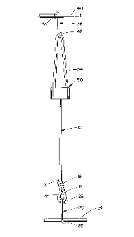
Figure lA is a top plan view of an adjustable length
cargo strap according to the present invention;
Figure lB is an enlarged perspective view of a central
portion of the cargo strap of Figure lA, in an upside down
orientation, with a line extending through a tensioner body
being shown in an untensioned, extended state;
Figure 2 is a top plan view of the tensioner body of
~igure lB;
Figure 3 is a cross-sectional view through the
tensioner body of Figure 2 along line 3-3;
2132267
--7--
Figure 4 i5 a cross-sectional view through the
tensioner body of Figure 2 along line 4-4;
Figure 5 is an enlarged perspective view of an upper
portion of the cargo strap of Figure lA in an upside down
orientation;
Figure 6 is a cross-sectional view through the
tensioner body of Figure 2 along line 6-6; and,
Figure 7 is a top plan view of another embodiment of
the cargo strap according to the present invention.
Detailed Description of the Preferred Embodiments
Referring now to the drawings, wherein the showings
are for purposes of illustrating preferred embodiments of
the invention only and not for purposes of limiting same,
Figures lA and 7 illustrate different configurations for a
cargo strap according to the present invention. While the
cargo strap and its tensioner device will be described and
illustrated particularly in connection with stretchable
resilient lines such as bungee cords, it should be
appreciated that the inventive tensioner device can be
utilized with any type of cable, rope or webbing whether or
not such line is resiliently extensible and contractable.
With reference now to Figure lA, the cargo strap and
tensioning device includes a line 10 having a first end 12
adjacent which a first loop 14 is formed by securing the
first end 12 to an adjacent line portion 16 by means of a
suitable conventional fastener 18. A first hook 20 is
selectively secured in the loop 14. The first hook has a
first end 22 which engages a first support member 24 and a
second end 26 which comprises at least one coil so as to
allow the line loop 14 to selectively extend through the
coil and thereby secure the hook 20 in place on the line
10. The hook 20 can be selectively dismounted from the
loop 14.
The line 10 can be a stretchable, flexible cargo strap
which has the property of generating restoring force when
~13226~
--8--
stretched from a relaxed condition to a tensioned
condition. Such straps are known and available from, e.g.
Stretch Products of West Warwick, Rhode Island. The line
can be, e.g. 5/16 inch thick fiberglas stranded cord which
is covered with a cloth material to prevent a fraying of
the strands of the cord. It should be appreciated,
however, that the line 10 could also be made from
substantially unstretchable cables, ropes or webs.
As shown in Figure lB, located on a second end 30 of
the line is an anchor means 32. This can, if desired,
comprise a simple loop or coil of a suitable conventional
wire material which is crimped into place on the line end.
In order to prevent fraying, a suitable potting material 33
can be provided on each end face of the line 10. With
reference again to Figure lA, a second loop 34 is provided
in the line in a spaced manner from the first loop 14.
Slidably secured in the second loop is a second hook 36.
This hook has a first end 38 which engages a suitable
conventional second support member 40. The second hook 36
also has a second coiled end 42 through which the second
loop 34 extends. The first and second support members 24
and 40 may be, e.g. the parallel spaced side rails of a
luggage rack on a motor vehicle.
Also provided is a tensioner 50. With reference now
to Figure lB, the tensioner includes a polygonal body 52.
The body 52 can have any desired shape. In the illustrated
embodiment, the body has three side surfaces 54 (only one
of which is visible in Fig. lB), a first end surface 56 and
a second end surface 58 (Fig. 5). With reference now also
to Figure 2, the tensioner 50 includes a first bore 62, a
second bore 64, a third bore 66 and a fourth bore 68.
Preferably, the four bores are spaced from each other and
have the same diameter. In addition, the bores are
preferably non-intersecting and are substantially parallel
to each other. Each of the bores extends from the first
end surface 56 to the second end surface 58 of the
tens~oner body 52.
2132267
With reference now to Figure 3, the first bore 62 can
be countersunk so as to have an enlarged diameter section
72. Preferably, the enlarged diameter section 72 is
colinear with the bore 62. This houses the line second end
30 and the anchor means 32. The latter contacts a shoulder
of the bore to prevent the line end 30 from being pulled
through the body 52. The first countersunk section 72
extends into the body from the first end surface 56
thereof. The bore 62 can be positioned in the body 52
anywhere in a 360- circle around the remaining trio of
bores 64, 66 and 68 since the location of the first bore is
not critical. On the other hand, the three other bores
need to maintain a specific orientation with regard to each
other.
With reference now also to Figure 4, also provided in
the tensioner body 52 is a second countersunk area 74 which
communicates with the second and third bores 64 and 66.
The second countersunk area 74 extends into the body from
the first end surface 56 thereof. With reference now also
to Figure 6, the body further includes a third countersunk
area 76 which communicates the second bore 64 with the
fourth bore 68. The third countersunk area 76 extends into
the body from the second end surface 58 thereof.
Formed in the second countersunk area 74 is a first
locking surface 78. Formed in the third countersunk area
76 is a second locking surface 80. Each of the locking
surfaces comprises a wall section defined by two of the
bores 64, 66 and 64, 68. It is evident that the locking
surfaces 78 and 80 are oriented normal to the respective
sets of bores 64 and 66 and 64 and 68. With reference now
also to Figure lB, located in the second countersunk area
74 is a third loop 86 of the line 10. Located in the third
countersunk area 76 (Fig. 6) is a fourth loop 88. It is
evident that the two loops 86 and 88 of the line are offset
from each other by an acute angle. That is, the center
lines extending through the two sets of bores 64, 66 and
64, 68 as evidenced by the cross-sectional lines 4-4 and 6-
21322~7
--10--
6 are spaced from each other by an acute angle. When these
loops are pulled tight in the tensioner 50, the respective
locking surfaces 78 and 80 will engage the line 10 and will
prevent any movement of the line 10 in relation to the
tensioner.
With reference again to Figure lA, slack in the line
10 can be taken up by the tensioner 50 when the hooks 20
and 36 are in place on the support members 24 and 40.
During this time, the tensioner device 50 moves easily in
relation to the line 10 as there is no tension on the line.
Once the slack has been taken out of the system, the
tensioner 50 holds the line tight and prevents any movement
of the line 10 and the tensioner in relationship to each
other. This occurs since the tensioner body 50 forces the
line 10 to make two 180- turns as is evident from Figure
lB. This configuration of the tensioner body allows the
pulling forces on the two hooks 20 and 36 to cancel each
other as the line is being pulled in precisely opposite
directions out bore 68 (Fig. lB) and bore 66 (Fig. 5).
It is noted that smooth, curved corners are provided
in the tensioner device 50, i.e. at the locking surfaces 78
and 80 so as to prevent any fraying of the line 10 as it
makes fairly tight radius bends within the tensioner body.
It should be evident that the larger the radius of the
bend, i.e. the larger the spacing of the two adjacent bores
in the tensioner body 50, the more there would be a
tendency for the line 10 to slip. Therefore, the bends or
loops of the line are kept fairly tight.
Both sections of the line 10, where the hooks 20 and
36 are mounted, are comprised of loop portions 14 and 34.
Such loops are advantageous in that there is less strain
produced on the line by the hooks as the tension of the
hook on the line is borne by both sections of line.
To secure a cargo to a cargo carrier, illustrated only
by the pair of support members 24 and 40 in Figure lA, one
provides an adjustable length cargo strap device that
includes the line 10 and the tensioner body 50. The first
2132267
--11--
hook 20 or attachment means is secured to the first support
member or cargo carrier element 24 and the second hook or
attachment means 36 is secured to the second support member
or cargo carrier element 40. The tensioner body 50 is then
slid in relation to the two hooks 20 and 36 until the slack
is removed from the line 10. Thereafter, a tension can be
exerted on the line 10 by further sliding the tensioning
body S0 until the line is taut and the means for
selectively binding the line 10 prevents a sliding motion
thereof in relation to the tensioner body 50. If the line
10 is a resilient extensible line, the line can be
stretched during the step of tensioning.
The tensioner body itself can be advantageously
injection molded from a suitable thermoplastic material.
On the other hand, the tensioner body could be made from a
suitable metal and investment cast. Alternatively, the
tensioner body could be made from a powdered metal and
formed by way of any suitable conventional forming process
such as hot isostatic pressure or the like. Plastic
materials are preferred for the tensioner body since
plastics are light, durable and of low cost. The tensioner
body can be provided in different sizes, i.e. with
different bore diameters for the bores 62, 64, 66 and 68
depending upon the diameter of the line 10 which is used.
In this connection, three different conventional sizes of
bungee cord type resilient extensible cable or cord are
known. These are 1/4 inch diameter(.635 cm.), S/16 inch
diameter (.794 cm.) and 3/8 inch diameter (.953 cm.) lines.
Such lines can come in either 3 or 6 foot lengths.
Accordingly, different sizes of tensioner bodies 50 can be
provided suitably mated to the right diameter line.
In one embodiment of the device, the tensioner body
has a larger dimension of 1.44 inches (3.66 cm.) and a
smaller dimension of approximately 1 inch (2.54 cm.) with
a thickness of .81 inches (2.06 cm.) The center line to
center line distance between, e.g. the second and third
bore 64 and 66, can be on the order of .44 inches (1.12
2132267
-12-
cm). This size tensioner has proven adequate for a cord
having a 3/8 inch diameter and a length of 6 feet. The
diameter of the several bores 62, 64, 66 and 68 can be on
the order of .375 inches (.953 cm.).
The hooks 20 and 36 can be made out of a suitable
plastic material, out of a metallic material, such as a
wire, or out of a rubber coated metal. While only one type
of slidable, selectively dismountable hook has been
illustrated, it should be evident that other conventional
hooks of this type can also be utilized. In addition,
attachment means other than hooks can be mounted on the
line 10. Such attachment means could comprise, e.g.,
rings, straps, links of chain, or the like. Each of these
could be slidable along the line 10 and selectively
dismountable if desired.
With reference now to Figure 7, an alternate
embodiment of the invention is there illustrated. For ease
of appreciation and understanding of this embodiment of the
invention, like components are identified by like numerals
with a primed (') suffix and new components are identified
by new numerals.
In this embodiment, a line 10' has on it a tensioner
body 50'. A first hook 20' is secured in a first loop 14'
adjacent one end of the line 10'. A second hook 36' is
secured in a second loop 34' of the line 10', spaced from
the first loop. The loop 34' is rather large in size and
affords room for slidably mounting a pair of additional
hooks. In this regard, a third hook 92 is secured to a
third support member 94 and, spaced therefrom, a fourth
hook 96 is secured to a fourth support member 98. In this
way, a web-like arrangement can be formed which may prove
advantageous in securing a sizeable piece of cargo 102 to,
e.g., a roof mounted carrier on a vehicle or the like.
The invention has been described with reference to
3S preferred embodiments. Obviously, modifications and
alterations will occur to others upon the reading and
understanding of this specification. It is intended to
2132267
include all such modifications and alterations insofar as
they come within the scope of the appended claims or the
equivalents thereof.