Language selection

Search

Patent 2132671 Summary

Third-party information liability

Some of the information on this Web page has been provided by external sources. The Government of Canada is not responsible for the accuracy, reliability or currency of the information supplied by external sources. Users wishing to rely upon this information should consult directly with the source of the information. Content provided by external sources is not subject to official languages, privacy and accessibility requirements.

Claims and Abstract availability

Any discrepancies in the text and image of the Claims and Abstract are due to differing posting times. Text of the Claims and Abstract are posted:

  • At the time the application is open to public inspection;
  • At the time of issue of the patent (grant).
(12) Patent: (11) CA 2132671
(54) English Title: HINGE FOR FURNITURE
(54) French Title: CHARNIERE DESTINEE A DU MOBILIER
Status: Expired and beyond the Period of Reversal
Bibliographic Data
(51) International Patent Classification (IPC):
  • E05D 03/02 (2006.01)
  • E05D 05/08 (2006.01)
  • E05F 01/12 (2006.01)
(72) Inventors :
  • BENEKE, ULRICH (Germany)
(73) Owners :
  • PAUL HETTICH GMBH & CO.
(71) Applicants :
  • PAUL HETTICH GMBH & CO. (Germany)
(74) Agent: SMART & BIGGAR LP
(74) Associate agent:
(45) Issued: 2003-12-30
(22) Filed Date: 1994-09-22
(41) Open to Public Inspection: 1995-03-24
Examination requested: 2001-06-12
Availability of licence: N/A
Dedicated to the Public: N/A
(25) Language of filing: English

Patent Cooperation Treaty (PCT): No

(30) Application Priority Data:
Application No. Country/Territory Date
G 93 14 375 (Germany) 1993-09-23

Abstracts

English Abstract


A furniture hinge has a housing (2) and a supporting
part (3) with an articulated connection and closing and
restraining device in the form of a flat spring (12) arranged
within the housing (2). The flat spring (12) works in conjunction
with a cam surface (10) during the opening movement of the hinge.
The flat spring (12) is arranged in the bottom (13) of the housing
(2), more or less parallel to this bottom part, and its middle
area is supported on a raised area (14) that is associated with
the bottom (13) of the housing. As a result of this arrangement
close to the bottom, the flat spring is very inconspicuous, and
does not detract from the appearance of the furniture. The flat
spring can be installed very easily and requires only a very
simple basic structure for the hinge type, so that the flat spring
can be used as required.


Claims

Note: Claims are shown in the official language in which they were submitted.

CLAIMS:
1. A hinge for use in pieces of furniture,
comprising:
a casing adapted for attachment to a door of a
piece of furniture and having a bottom provided with a bump;
a support member for attachment to a wall of the
piece of furniture and including at least one bearing insert
projecting into said casing for defining at least one joint
connection between said support member and said casing and
including a peripheral cam in the area of the joint
connection;
a closing and locking means in form of a flat
spring having one end cooperating with said peripheral cam
during opening of the hinge and another end, said flat
spring being arranged in the area of said bottom of said
casing at approximately parallel relationship thereto and
defining a central area which is supported by said bump of
said bottom, and
an adjusting member situated at said other end of
said flat spring for allowing a modification of a distance
between said bottom and said flat spring.
2. A hinge as defined in claim 1 wherein said flat
spring has another, end which traverses an opening in said
bottom and is supported by an underside of said bottom.
13. A hinge as defined in claim 1 wherein said
adjusting element is a screw acting upon said flat spring.
7

4. A hinge as defined in claim 3 wherein said screw
threadably engages said bottom to act with a shoulder upon
said flat spring.
5. A hinge as defined in claim 3 wherein said screw
has a lower end provided with a pin which engages a bore of
said flat spring.
6. A hinge as defined in claim 1 wherein said flat
spring is a single leaf spring.
7. A hinge as defined in claim 1 wherein said flat
spring is configured at least partly as a two-layer leaf
spring.
8. A hinge as defined in claim 1 wherein said flat
spring is a wire strap type spring.
9. A hinge as defined in claim 1 wherein said
adjusting member is a rotatable disk with an ascending or
descending end face for support of said flat spring.
10. A hinge as defined in claim 1 wherein said
adjusting member is a linearly displaceable wedge.
11. A hinge as defined in claim 10 wherein said wedge
has effective surfaces provided with grooves.
12. A hinge as defined in claim 1 wherein said bump of
said bottom is created by a bead formed in said bottom.
13. A hinge as defined in claim 1 wherein said bottom
is provided with several spaced receiving openings, said
bump of said bottom being formed by an insert which is
selectively engageable in one of said receiving openings in
said bottom.
8

14. A hinge as defined in claim 1 wherein said support
member includes a pressure piece having a stop surface, said
peripheral cam being formed on said pressure piece and
continues into said stop surface which supports said flat
spring in closing position.
9

Description

Note: Descriptions are shown in the official language in which they were submitted.


23724-216
The present invention relates to a hinge for furniture,
this consisting of a housing that is in stalled on the door-side
and a supporting part that can be installed in the side of the
furniture, with at least one bearing shoulder that extends into
the housing and supports at least one of the bearing points that
create the articulated connection to the housing; a closing or
restraining device in the form of a flat spring is arranged within
the housing, and one end of this is acted upon by a cam surface
that is provided in the area of the bearing point during the
opening movement of the hinge.
Tn commercially available hinges of this kind, the flat
spring, for example in the form of a leaf spring, extends
relatively far into the housing space, and this is unattractive
from the standpoint of appearance. A special structure that is
integrated into the usual functional parts of the hinge is
provided to support it, in 'the sense of a pre-tensioning, and this
is relatively costly and has to be used, in the sense of
integration, in the event that a closing or restraining device is
not required in a special application.
P'or 'this reason, it is the task of the present invention
to create a hinge of this type, in which, for all practical
purposes, the closing or restraining device is not visually
unappealing, can be manufactured and installed simply and
economically, and in particular, given the simple basic structure
of the hinge type, can be used without any problems, as desired.
Essentially, the solution according to the present
invention is such that the flat spring is arranged in the area of
1

CA 02132671 2003-07-24
23724-216
the bottom of the housing, approximately parallel to this,
and its middle area is supported on a raised area that is
associated with the bottom of the housing.
The arrangement of the flat spring in the vicinity
of the bottom, parallel to this, ensures that it is
particularly inconspicuous, which is to say it does not
disrupt the overall visual and aesthetic impression created
by the furniture in the area of the hinge, and for this
reason increases the utility value of the furniture. The
basic design of the hinge with its other functional elements
requires only insignificant modifications. In the simplest
case, the support for the middle area of the flat spring can
consist of a small bead that is formed in the bottom of the
housing. In this respect, given a simple basic structure,
it is also possible to manufacture hinges either with or
without closing or restraining devices. When they are used,
the flat springs can be installed very simply. In a
preferred configuration that is of a particularly simple
design, the end of the flat spring that is remote from the
cam surface can pass through a small opening in the bottom
of the housing and rest against the underside of this. This
also contributes to keeping the basic design of the hinge
simple and, should it be necessary, providing a closing and
restraining device that can be manufactured and installed
economically and simply, which operates reliably, and which
wears very little.
An adjuster element is associated with the end of
the flat spring that is remote from the cam surface; this
adjuster can be used to vary the distance between the bottom
of the housing and the flat spring. This, too, is simple to
configure from the design standpoint, and offers the
2

CA 02132671 2003-07-24
23724-216
advantage that the closing and restraining force can be
adjusted or set.
A further possibility for varying the spring
force, which is simple from the design standpoint, is seen
in a preferred embodiment and is such that the raised area
of the bottom of the housing that supports the flat spring
is formed from an insert, for which a plurality of
receptacles that are spaced apart from each other are
provided in the bottom so that, depending on the receptacle
that is chosen, it is possible to vary the support point and
the breakover point of the flat spring.
The invention may be summarized as a hinge for use
in pieces of furniture, comprising: a casing adapted for
attachment to a door of a piece of furniture and having a
bottom provided with a bump; a support member for attachment
to a wall of the piece of furniture and including at least
one bearing insert projecting into said casing for defining
at least one joint connection between said support member
and said casing and including a peripheral cam in the area
of the joint connection; a closing and locking means in form
of a flat spring having one end cooperating with said
peripheral cam during opening of the hinge and another end,
said flat spring being arranged in the area of said bottom
of said casing at approximately parallel relationship
thereto and defining a central area which is supported by
said bump of said bottom, and an adjusting member situated
at said other end of said flat spring for allowing a
modification of a distance between said bottom and said flat
spring.
Embodiments of a hinge according to the present
invention are described in detail below on the basis
3

CA 02132671 2003-07-24
23724-216
of the drawings appended hereto. These drawings show the
following:
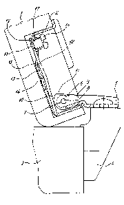
Figure 1: A hinge according to the present
invention, in cross section, when in the open position;
Figure 2: The hinge as in Figure 1, in cross
section, when in the closed position;
Figure 3: Another embodiment of a hinge according
to the present invention, in partial cross section;
Figures 4 and 5: Additional embodiments of
adjusters for the flat spring;
Figures 6, 7, 8: Additional embodiments of this
type of flat spring;
Figure 9: A partial cross section through the
bottom of the housing, with a variable support for the flat
spring.
3a

23724-216
The hinge for furniture that is shown in Figures 1 and 2
has a housing 2 that can be installed in the door 1 and a
supporting part that can be installed in a furniture side that is
adjacent thereto, this consisting of a mounting plate 4 and a side
part 5. The Side part 5 of the supporting part has at least one
bearing shoulder 6 that extends into the housing 2, and that forms
at least one support point 7, for example for a pin 8, and thus
forms the articulated connection to the housing 2.
The side part 5 also supports a pressure piece 9 that
projects into the housing 2; at its unattached end, this
incorporates a cam surface 10 that becomes a flat stop surface 11.
A closing and retaining device in the form of a flat
spring is arranged within the housing 2; in the embodiment shown
in Figures 1 and 2, this is a single-layer leaf spring 12. The
leaf spring 12 is located inconspicuously in the area of the
bottom 13 of the housing 2, more or less parallel to this, and in
its middle area is supported by a raised section 14 that is
associated with the bottom 13 of the housing. Tn the embodiment
shown in Figures 1 and 2, this is formed very simply by a bead
that is formed in the bottom 13.
One end of the leaf spring 12 lies, suitably tensioned
during the opening movement of the hinge, on the cam surface 10
(see~Figure 1), When the door is in the closed position (Figure
2), the leaf spring 2 acts on the stop surface 11 of the cam
surface 10.
The other end of the leaf spring 12 passes through an
opening in the bottom 13 of the housing, and is supported on the
4

23724-216
underside of the bottom 13. In the embodiment that is shown in
Figures 1 and 2, an adjuster in the form of a screw 16 is
associated with the end of the leaf spring 12 that is remote from
the cam surface 10; 'this screw 16 is screwed into a threaded
opening in the bottom 13 o.f the housing, and acts through a
shoulder 17 on the leaf spring 12. The distance from the leaf
spring 12 to the bottom of the housing, and thus 'the tension on
the leaf spring 12, can be varied by this screw.
At its lower end, the screw has a stud 18 that passes through a
bore 19 in the leaf spring 12 and this keeps the leaf spring in
position.
Figure 4 shows another embodiment of an adjuster of this
type, this being in the form of a disk 16a with a rising or
falling face surface against which a flat spring can rest. Such a
disk 16a could be supported, for example, so as to be able to
rotate within the bottom 13 of the housing. The face surface
would then lie underneath, facing the flat spring 12; the disk
could have a slot far a screwdriver at the top, sa that it would
be simple to turn.
Another possible adjuster is shown in Figure 5. Tn this
embodiment, this is a wedge 16b that would be arranged beneath the
bottom 13 of the housing so as to be able to move linearly; an
''' elongated slot could then be provided in the bottom 13,'through
which it would be possible to move the wedge 16b.
The wedge 16b can be provided with grooves 20 to hold it
in place. The distance between the flat spring l2 and the bottom
13 of the housing can also be varied by moving such a wedge.
5

23724°216
Figure 3 shows an embodiment of particularly simple
design. In this, the leaf spring 12 is supported on the underside
of the bottom 13 of the housing, without any adjuster; a bead 21
that projects downward is formed in the bottom 13.
Figures 6, 7, and 8 show additional possible embodiments
of flat springs. In the embodiment shown in Figure 6, a two-7.ayer
curved leaf spring 12a is used. The curved leaf spring 12b shown
in Figure 7 is only partially formed with two layers. The flat
spring 12c shown in Figure 8 is in the form of a wire-clip spring.
A further possibility for varying the pre-tensioning of
the flat spring 12 is shown in Figure 9, In this embodiment, the
raised portion that is associated with the bottom 13 of the
housing, on which the midda.e area of the flat spring 12 rests, is
formed by an insertion, for example, a wire pin 22. Receiving
openings 23 that are spaced apart from each other are made in the
bottom of the housing 13 for this wire pin 22. The support point
for the flat spring, relative to its length, can be varied by
selecting one of the receiving openings, and this also varies the
breakwer point of the spring.
The configuration according to the present invention,
described above, is suitable fox any hinges of this basic type,
regardless of the number of points of rotation, axes of rotation,
and ~articula~ted levers.
6

Representative Drawing
A single figure which represents the drawing illustrating the invention.
Administrative Status

2024-08-01:As part of the Next Generation Patents (NGP) transition, the Canadian Patents Database (CPD) now contains a more detailed Event History, which replicates the Event Log of our new back-office solution.

Please note that "Inactive:" events refers to events no longer in use in our new back-office solution.

For a clearer understanding of the status of the application/patent presented on this page, the site Disclaimer , as well as the definitions for Patent , Event History , Maintenance Fee  and Payment History  should be consulted.

Event History

Description Date
Time Limit for Reversal Expired 2009-09-22
Letter Sent 2008-09-22
Inactive: IPC from MCD 2006-03-11
Grant by Issuance 2003-12-30
Inactive: Cover page published 2003-12-29
Pre-grant 2003-10-07
Inactive: Final fee received 2003-10-07
Notice of Allowance is Issued 2003-09-11
Letter Sent 2003-09-11
Inactive: Approved for allowance (AFA) 2003-08-29
Amendment Received - Voluntary Amendment 2003-07-24
Inactive: S.30(2) Rules - Examiner requisition 2003-05-01
Inactive: Application prosecuted on TS as of Log entry date 2001-06-29
Letter Sent 2001-06-29
Inactive: Status info is complete as of Log entry date 2001-06-29
All Requirements for Examination Determined Compliant 2001-06-12
Request for Examination Requirements Determined Compliant 2001-06-12
Application Published (Open to Public Inspection) 1995-03-24

Abandonment History

There is no abandonment history.

Maintenance Fee

The last payment was received on 2003-07-28

Note : If the full payment has not been received on or before the date indicated, a further fee may be required which may be one of the following

  • the reinstatement fee;
  • the late payment fee; or
  • additional fee to reverse deemed expiry.

Patent fees are adjusted on the 1st of January every year. The amounts above are the current amounts if received by December 31 of the current year.
Please refer to the CIPO Patent Fees web page to see all current fee amounts.

Fee History

Fee Type Anniversary Year Due Date Paid Date
MF (application, 3rd anniv.) - standard 03 1997-09-22 1997-09-12
MF (application, 4th anniv.) - standard 04 1998-09-22 1998-09-11
MF (application, 5th anniv.) - standard 05 1999-09-22 1999-08-18
MF (application, 6th anniv.) - standard 06 2000-09-22 2000-08-18
Request for examination - standard 2001-06-12
MF (application, 7th anniv.) - standard 07 2001-09-24 2001-07-18
MF (application, 8th anniv.) - standard 08 2002-09-23 2002-08-07
MF (application, 9th anniv.) - standard 09 2003-09-22 2003-07-28
Final fee - standard 2003-10-07
MF (patent, 10th anniv.) - standard 2004-09-22 2004-08-30
MF (patent, 11th anniv.) - standard 2005-09-22 2005-09-08
MF (patent, 12th anniv.) - standard 2006-09-22 2006-09-06
MF (patent, 13th anniv.) - standard 2007-09-24 2007-09-05
Owners on Record

Note: Records showing the ownership history in alphabetical order.

Current Owners on Record
PAUL HETTICH GMBH & CO.
Past Owners on Record
ULRICH BENEKE
Past Owners that do not appear in the "Owners on Record" listing will appear in other documentation within the application.
Documents

To view selected files, please enter reCAPTCHA code :


To view images, click a link in the Document Description column (Temporarily unavailable). To download the documents, select one or more checkboxes in the first column and then click the "Download Selected in PDF format (Zip Archive)" or the "Download Selected as Single PDF" button.

List of published and non-published patent-specific documents on the CPD .

If you have any difficulty accessing content, you can call the Client Service Centre at 1-866-997-1936 or send them an e-mail at CIPO Client Service Centre.

({010=All Documents, 020=As Filed, 030=As Open to Public Inspection, 040=At Issuance, 050=Examination, 060=Incoming Correspondence, 070=Miscellaneous, 080=Outgoing Correspondence, 090=Payment})


Document
Description 
Date
(yyyy-mm-dd) 
Number of pages   Size of Image (KB) 
Representative drawing 1998-03-03 1 17
Claims 2003-07-23 3 73
Representative drawing 2003-09-01 1 7
Description 2003-07-23 7 238
Drawings 1995-06-05 3 55
Description 1995-06-05 6 606
Abstract 1995-06-05 1 88
Claims 1995-06-05 3 276
Reminder - Request for Examination 2001-05-22 1 117
Acknowledgement of Request for Examination 2001-06-28 1 179
Commissioner's Notice - Application Found Allowable 2003-09-10 1 160
Maintenance Fee Notice 2008-11-02 1 171
Correspondence 2003-10-06 1 31
Fees 2002-08-06 1 38
Fees 1996-08-11 1 43