Language selection

Search

Patent 2133211 Summary

Third-party information liability

Some of the information on this Web page has been provided by external sources. The Government of Canada is not responsible for the accuracy, reliability or currency of the information supplied by external sources. Users wishing to rely upon this information should consult directly with the source of the information. Content provided by external sources is not subject to official languages, privacy and accessibility requirements.

Claims and Abstract availability

Any discrepancies in the text and image of the Claims and Abstract are due to differing posting times. Text of the Claims and Abstract are posted:

  • At the time the application is open to public inspection;
  • At the time of issue of the patent (grant).
(12) Patent: (11) CA 2133211
(54) English Title: BRIDGE MODULE
(54) French Title: ELEMENT MODULAIRE DE PONT
Status: Expired and beyond the Period of Reversal
Bibliographic Data
(51) International Patent Classification (IPC):
  • E01D 15/12 (2006.01)
  • E01D 15/133 (2006.01)
  • E01D 15/14 (2006.01)
  • E01D 21/00 (2006.01)
(72) Inventors :
  • CONNOR, RICHARD CHARLES (United Kingdom)
  • MITCHELL, KEITH JOHN (United Kingdom)
(73) Owners :
  • SECRETARY OF STATE FOR DEFENCE IN HER BRITANNIC MAJESTY'S GOVERNMENT
  • QINETIQ LIMITED
(71) Applicants :
  • SECRETARY OF STATE FOR DEFENCE IN HER BRITANNIC MAJESTY'S GOVERNMENT (United Kingdom)
  • QINETIQ LIMITED (United Kingdom)
(74) Agent: SMART & BIGGAR LP
(74) Associate agent:
(45) Issued: 2004-07-20
(86) PCT Filing Date: 1993-04-02
(87) Open to Public Inspection: 1993-10-28
Examination requested: 1999-08-27
Availability of licence: N/A
Dedicated to the Public: N/A
(25) Language of filing: English

Patent Cooperation Treaty (PCT): Yes
(86) PCT Filing Number: PCT/GB1993/000704
(87) International Publication Number: GB1993000704
(85) National Entry: 1994-09-28

(30) Application Priority Data:
Application No. Country/Territory Date
9208291.6 (United Kingdom) 1992-04-15

Abstracts

English Abstract


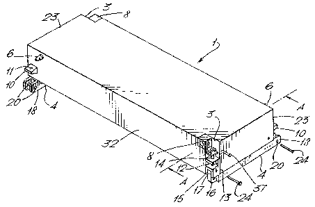
A module for constructing a modular bridge suitable for use in both a dry span
and a floating role comprising a bouyant
structure (32) having interconnection means (6, 10, 11, 8, 3, 13, 12, 37,14)
for connecting the module end to end to an adjacent
similar module to form a bridge and having one or more link members (4) which
are releasably securable to the underside of the
bridge module (1) by link securing means (not shown in figure 1). Each link is
provided at one end with a double limb connection
member (18) and at the other with a complementary single limb connection
member, both provided with holes (20) for insertion
of a pin to connect two links from adjacent bridge modules together. The
releasably securable link members (4) are removed from
a bridge assembled for a floating role to reduce redundant weight.


Claims

Note: Claims are shown in the official language in which they were submitted.


10
CLAIMS:
1. Bridge module comprising a buoyant structure with
at least one end having module interconnection means for
connecting the module end to end to an adjacent module so as
to form a bridge comprising a plurality of said modules the
module further comprising at least one link member with link
connection means and link securing means the or each link
member being releasably securable to the buoyant structure
by the link securing means and being longitudinally
connectable to a link member of an adjacent module via the
link connection means to support tensile forces experienced
by a bridge comprising a plurality of said modules.
2. A module as claimed in claim 1 wherein the or each
link member is connectable to the module adjacent a lower
surface of the module.
3. A module as claimed in claim 1 or claim 2 wherein
a link member is provided adjacent each side of the module.
4. A module as claimed in any one of claims 1 to 3
wherein interconnection of two modules aligns the link
connection means of the link members of the interconnected
modules.
5. A module as claimed in any one of claims 1 to 4
wherein each link has differing first and second ends
constituting the link connection means the first end of a
link being complementarily connectable to the second end of
a similar link.
6. A module as claimed in any one of claims 1 to 5
wherein the link connection means is configured so that
longitudinal connection of two links may be effected with a
single pin.

11
7. A module as claimed in claim 6 wherein the link
connection means is configured so that connection may be
effected by horizontal insertion of a pin from a side of the
module.
8. A module as claimed in any one of claims 1 to 7
wherein the securing means for releasably securing the or
each link member to the buoyant structure comprises a pinned
connection.
9. A module as claimed in any one of claims 1 to 8
wherein the link securing means includes two upstand members
for engagement with the buoyant structure.
10. A module as claimed in claim 9 wherein the upstand
members are accommodated in recesses in the buoyant
structure.
11. A module as claimed in claim 9 or claim 10 wherein
the buoyant structure includes a block which constitutes
part of the module interconnection means and also has a
recess for accommodating a link upstand member.
12. A module as claimed in any one of claims 1 to 11
wherein the modulus of elasticity of material constituting a
majority of the or each link member is more than twice that
of material constituting a majority of the buoyant
structure.
13. A module as claimed in any one of claims 1 to 12
wherein the or each link member is made from an alloy
containing ferrous material or from a fibre reinforced
plastics material.
14. A module as claimed in any one of claims 1 to 13
wherein a majority of the buoyant structure is made of
aluminium or an alloy thereof.

12
15. A module as claimed in any one of claims 1 to 14
wherein the link connection means is made of metal.
16. A module as claimed in any one of claims 1 to 15
wherein the or each link projects below a lower surface of
the buoyant structure and has a substantially projection
free under side.
17. A module as claimed in any one of claims 1 to 16
wherein two opposing ends of the module each have
interconnection means for connecting the module to an
adjacent module.
18. A bridge module as claimed in any one of claims 1
to 17 having a link member which is connected at a first end
to the buoyant structure for transmission of link tension
forces to the buoyant structure and is longitudinally
connectable to a link member of an adjacent module at a
second end.
19. A modular bridge comprising a plurality of modules
as claimed in any one of claims 1 to 18 interconnected with
the link members of adjacent modules connected via the link
connection means.
20. A method of launching the bridge claimed in claim
19 including the step of rolling the bridge over a support
structure configured to support the bridge by means of the
link members.

Description

Note: Descriptions are shown in the official language in which they were submitted.


_2I332~~
WO 93/21390 PCT/GB93/00704
The present invention relates to modules for constructing
modular bridges which are designed to be used in both a dry span role
and as floating bridges.
Where there is a requirement to transport a bridge to a
particular location and construct it in a short time such as in
military operations or in response to a civil disaster modular bridges
comprising interconnectable modules are often used. In order to
increase the versatility of such bridges they are sometimes designed
to bemused either in a dry span role or alternatively as floating
bridges. Such a design has the added advantage that the bridge can
also be used as a ferry. An example of such a bridge is referred to
at page 110 of Jane's Military Vehicles and Logistics 191. As'the
bridge must have sufficient flexural rigidity when used in the dry
span role there is a certain amount of structural redundancy when the
bridge is used as a floating bridge or ferry as the natural buoyancy
of the bridge supports the majority of the weight of the bridge and
any payload borne by the bridge. The consequence of this redundancy
is that the weight of the bridge is unnecessarily high when the bridge
is afloat and the load that the bridge can support when afloat is
accordingly reduced.
The object of the invention is to provide a module for a modular
bridge which can be used to build a bridge for use in the dry span
role or alternatively as a floating bridge and which does not suffer
from the disadvantage described above.
Thus according to the invention there is provided.a bridge
module comprising a buoyant structure with at least one end having
module interconnection means for connecting the module end to end to
an adjacent module so as to form a bridge comprising a plurality of
said modules the module further comprising at least one link member

':::i3f
WO 93/21390 ~CI~lGB93/00704
~~~32~~.~.. -
with link connection means and link securing means the or each link
member being releasably securable to the buoyant structure by the link
securing means and being longitudinally connectable to a link member
of an adjacent module via the link connection means to support tensile
forces experienced by a bridge comprising a plurality of said modules.
A bridge can be constructed from bridge modules made according
to the invention which can have a high load carrying capacity in the
dry span role and yet not suffer from having unnecessary weight caused
by redundant strength when used as a floating bridge due to the fact
that the link members can be removed in such circumstances.
In order to maximise the. load carrying capacity of a bridge
module including a link member having a particular stiffness the or
each link member is preferably connectable to the module adjacent a
lower surface of the module so as to increase the second moment of
area of the cross section of the module.
In order to reduce the tendency of a bridge module to twist when
loaded eccentrically a link member is preferably provided on each side
of the module.
So as to facilitate assembly of a plurality of modules into a
bridge structure interconnection of two modules preferably aligns the
link connection means of the link members of the interconnected
modules.
In order that a single design of link may be used throughout a
bridge struct~ire preferably each link'has differing first and second
ends constituting the link connection means the first end of a link
being complementarily connectable to the second end of a similar link.
In order to facilitate construction of a bridge for use in the
dry span role the link connection means is preferably configured so

.,--:-
~ ~ ~ ~ ~ ~ ~ ~crlc~93loo~oa
WO 93121390
-3-
that connection may be effected by horizontal insertion of a single
pin from a side of the module.
In order to facilitate removal of the or each link member from
the module the securing means for releasably securing the or each link
member to the buoyant structure preferably comprises a pinned
connection.
in order to safely secure each link member to the buoyant body
in a manner which is not likely to interfere with anything passing
below the bridge the link securing means preferably includes two
upstand members which are accommodated in recesses in the buoyant
structure where they may be secured.
In order to reduce the'weight of and the number of components
incorporated in a module the buoyant structure preferably includes a
block which constitutes part of the module interconnection means and
also has a recess for accommodating a link upstand member.
In order that link members in a bridge constructed using modules
made according to the invention attract a high proportion of the
tensile forces experienced by the modules at an early stage of bridge
loading the modulus of elasticity of material constituting a majority
of the or each link member is preferably more than twice that of
material constituting a majority of the buoyant structure.
Materials having a suitably high modulus of elasticity for
manufacturing the links from include an alloy containing ferrous
material and fibre reinforced plastics material. When the link member
is made from reinforced plastics material it preferably has an end
connection made from metal.

d,
WO 93121390 P(T/GB93/00704
~~332~.1 _
A suitably strong and robust material for fabricating the
buoya.-~t module from is aluminium or an alloy thereof. A lightweight
module made from such a material provides the potential for structures '
which can be hand built and which are easily portable by air.
In order to facilitate the launching of a bridge fabricated from
a plurality of modules over rollers the or each, link preferably
projects below a lower surface of the buoyant structure and has a
substantially projection-free underside. The advantage of supporting
such a bridge by means of the link members running over support
rollers is that the presence of the link members can be ensured when
the bridge is being launched over a dry gap. This will prevent
launching of the bridge for use in the dry span role with the link
members inadvertently omitted.
The invention provides in its second aspect a modular bridge
comprising a plurality of modules as described above interconnected
with link members of adjacent modules connected via the link
connection means.
The invention provides in its third aspect a method of launching
a bridge as described above including the step of rolling the bridge
over a support structure configured to support the bridge by means of
the link members.
The invention will now be described by way of example only with
reference to figures 1 to 9 in which;
Figure d Shows a perspective view of a bridge module
constructed in accordance with the first aspect
of the invention.
Figure 2 Shows a vertical section on the line AA through
the module shown in figure 1.

2 .~ 3 3 2 I .~
r __
WO 93!21390 PCT/GB93l00704
Figure 3 Shows a horizontal section on the line HH of the
link member shown in figure 2.
Figure 4 Shows a partial vertical cross section of a ramp
module.
Figures 5 to 8 Show the sequence involved in launching a bridge
constructed according to the second aspect of
the invention.
Figure ~ Shows a vertical section on the line CC through
the bridge and part o~f the support structure
shown in figure 6.
Figure 1 shows a bridge module 1 constructed according to the
invention. The basis of the module is a box like buoyant structure 32
of aluminium alloy (having a modulus of elasticity in the order of
71x103 MPa). Each end 23 of the module which is designed to be
connected to another module is provided wit~n a spigot 8 near ore top
corner and a socket 8 adjacent its other top corner which is
dimensioned to receive a spigot 6 of an adjacent module. Each spigot
6 has a horizontal hole in it to.accommodate a socket pin 3'7 which can
be passed through an interengaged socket and spigot. Spigots 6 and
sockets 8 on opposing~~sides 23 of the module shown in figure 1 can be
seen. Below each spigot 6 a tapered lug 10 is provided with a
vertical lug hole 11. Adjacent to each socket 8 the buoyant structure
32 is provided with a vertical,corner recess 3 containing a housing
block 13. The housing block has a first slot 12 in its upper portion
which is tapered complementarily with lug 10 and is provided with a
captive pin 14 which can be lowered into the housing to engage a lug
of an interengaged module.

WO 93/21390 ~ ~ ~'1'1 PG~'/G~93100704
a~,I
Running along each end of the under surface of the module is a
link 4 which is shown in detail in figures 2 and 3. Each link is
connected to the buoyant structure 32 by means of link securing pins
24 which pass through link upstand members 17 and 21 of the link. The
link upstand member 17 at one end of the link 4 is retained in a '
'.
recess 15 in the lower portion of the housxng~block 13. The link
upstand member 21 at the other end of the link is retained in a recess
19 in the buoyant structure 32. At one end of each link a steal
single limb connection member 16 is provided and at the opposite end
of the link a steel double limb connection member 18 is provided. The
connection members 16 and 18 are configured such that a single limb
connection member 16 on one link can pass between the limbs of a
double limb connection member 18 of another link. Each limb is
provided with a hole 20 so that a link connecting pin 22 (see figure
3) can be passed through a pair of engaged connection members 16 and
18 in order to connect two links together. The links at each end of
the module face in opposite directions so that each end face 23 of a
.module which is adapted for connection to an adjacent module presents
a double limb connection member 18 at one side of its lower edge and a
single limb connection member 16 at the opp~ysite side of its lower
edge.
The construction of a link member 4 is shown in figures 2 and 3.
Figure 2 is a vertical section on the line AA through the module shown
in figure 1 and figure 3 is a horizontal section on the line BB of the
link member 4 shown in figure 2. The link comprises a central portion
26 of carbon fibre reinforced plastics material (having a modulus of
elasticity in the.region of 200x103 MPa) with the fibres aligned to
run longitudinally along the length of the link. Glued into each end
of the central portion 26 is a stepped portion 28 of a Tink connection
member 16 or 18. In addition to being glued in place each connection
member 16 or 18 is secured to the central portion 26 by clamping pins
30 which pass through both the central portion 26 and a connection
member.

-- 2~~3~~~
--.;
WO 93121390 ' PGTJGB93/00704
-7-
The entire link member may alternatively be fabricated from
steel having a modulus of elasticity in the order of 190x103 iHPa.
Two modules can be connected together by confronting an end 23
of a first module with an end 23 of a second module. The spigot 6 and
lug 10 of each confronting face may then be engaged with the socket 8
and first slot 12 respectively of the other confronting face. The
captive pins lei (one on each module) may then be lowered into their
respective housing blocks 13 in order to lack both lugs 10 in place
and a socket pin 37 may be slid horizontally into each socket 8 (one
on each module) in order to lock the spigots 6 in place. When the
bridge is to be used in the dry span role the links 4 are left in
place as shown in figures 1 and 2 and link connection pins 22 are
inserted into engaged pairs of connecting members 16 and 18 in order
to connect the link members on each side of the bridge together. When
however the modules are to be'used to construct a floating bridge or a
ferry the link members 4 may be removed in order to remove redundant
weight. The link member at each end of a-module may be removed by
extracting the link securing pins 24 which secure it in place and
lowering it away from the module. ~By adding more modules on in a
similar manner a bridge or ferry structure with the link members
present or absent as required can be built up.
A bridge constructed using the modules described above will
normally be prcvided with a ramp module 2 at each end. Figure 4 shows
a part vertical cross section of a ramp module through the ramp link
at one end of the module. The left hand side of the ramp module seen
in figure 4 includes a spigot, socket, lug and housing block
arrangement the same as'that provided on the left hand~side of a
standard module shown in figures 1 and 2 and has been omitted from
figure 4. The ramp module tapers towards a ramp toe 36 in order to
facilitate the passage of vehicles on and off the bridge or ferry. At
each end of the ramp module a ramp link member 9 is provided. As
there will not normally be a necessity to connect the toe end of the

1W0 93!21390 PC'T/G1393/00704
_g_
e~1332~.~.
ramp module to another module each ramp link member 9 does not pra~ect
beyond the toe 36. Ramp modules without links can be coupled together
in overlapping relationship in order to form a large floating bridge
from a number of smaller floating bridge or ferry assemblies. The end
of the ramp link member nearest to the toe.=36 is provided with a load
distribution plate 34 with retaining pin..holes 39~ 'tee plate 34 is
engageable with a recess 35 in the ramp module. The plate 34 is used
firstly to hold the ramp link member 9 in place underneath the ramp
module to aid construction of a bridge and secondly to transfer
tensile forces from interconnected link members in a loaded dry span
bridge to the remainder of the bridge structure.
A method of launching a dry span bridge constructed from the
modules described above including link members will now be described
with reference to figures 5 to g.
A support structure 40 is made up on the near bank 58 and a
probe ~uppert 50 is located on the far bank 60. The support structure
40 (see figures 5 and 9) comprises a frame pivot 54 supporting a
roller frame 52. A roller shaft 45 extends across each end of the
roller frame 52 and extends outside the roller frame in order to
support a roller 46 on each side of the frame. The two rollers on one
side of the frame are spaced from the two rollers on the other side of
the frame by the distance between the link members of a module. A
probe roller 56 is positioned centrally on each roller shaft 45.
A light weight probe 48 made up from sections is fabricated.
The length of the probe 48 is selected to suit the width of the gap
that is to be' bridged.This assembly is then rolled towards the far
bank centrally over the roller frame 52 supported on probe rollers 56
at each end of the roller frame. As more probe is cantilevered over
the gap to be bridged bridge modules are connected to the probe in
order to balance the structure over the frame pivot 54. Firstly a
ramp module 2 is connected to the probe 48. Thereafter standard

i.r_:. _ 213 3 21 ~.
WO 93/21390 PCf/G~93/00704
-9-
modules 1 are connected as described above until a sufficient number
have been added to farm a bridge of adequate length. The modules are
supported on the roller frame 52 by means of the link members 4
engaging the rollers 46. As the modules are joined on the bridge and
probe are rolled further towards the far bank 60 and the probe 48 is
dismantled section by section as it passes over the probe support 50
and becomes redundant. When the bridge is of a sufficient length a
second ramp module 2 is connected as shown in figure ~ and a
supplementary support 62 is placed under the end of the frame 52
nearest to the far bank. Jacks 64 are then used to jack up each end
of the bridge in order to allow the remaining probe section 48 to be
removed from the bridge and the support structure 40 and probe support
50 to be removed. The bridge may then be lowered to the ground for
use. Removal of the bridge is carried out by reversing the procedure
described above.
When constructing a bridge for use -as a ferry or for use as a
floating bridge the link members can be omitted as mentioned above.
Construction for such use can conveniently be effected by joining the
modules together while they are floating in the water.

Representative Drawing
A single figure which represents the drawing illustrating the invention.
Administrative Status

2024-08-01:As part of the Next Generation Patents (NGP) transition, the Canadian Patents Database (CPD) now contains a more detailed Event History, which replicates the Event Log of our new back-office solution.

Please note that "Inactive:" events refers to events no longer in use in our new back-office solution.

For a clearer understanding of the status of the application/patent presented on this page, the site Disclaimer , as well as the definitions for Patent , Event History , Maintenance Fee  and Payment History  should be consulted.

Event History

Description Date
Time Limit for Reversal Expired 2008-04-02
Letter Sent 2007-04-02
Inactive: IPC from MCD 2006-03-11
Grant by Issuance 2004-07-20
Inactive: Cover page published 2004-07-19
Inactive: Final fee received 2004-05-07
Pre-grant 2004-05-07
Inactive: Office letter 2003-11-17
Notice of Allowance is Issued 2003-11-14
Letter Sent 2003-11-14
Inactive: Approved for allowance (AFA) 2003-11-03
Inactive: Correspondence - Transfer 2003-10-21
Letter Sent 2003-10-21
Amendment Received - Voluntary Amendment 2003-09-15
Inactive: S.30(2) Rules - Examiner requisition 2003-03-24
Letter Sent 1999-09-14
Inactive: Status info is complete as of Log entry date 1999-09-13
Inactive: Application prosecuted on TS as of Log entry date 1999-09-13
Request for Examination Requirements Determined Compliant 1999-08-27
All Requirements for Examination Determined Compliant 1999-08-27
Application Published (Open to Public Inspection) 1993-10-28

Abandonment History

There is no abandonment history.

Maintenance Fee

The last payment was received on 2004-03-18

Note : If the full payment has not been received on or before the date indicated, a further fee may be required which may be one of the following

  • the reinstatement fee;
  • the late payment fee; or
  • additional fee to reverse deemed expiry.

Patent fees are adjusted on the 1st of January every year. The amounts above are the current amounts if received by December 31 of the current year.
Please refer to the CIPO Patent Fees web page to see all current fee amounts.

Owners on Record

Note: Records showing the ownership history in alphabetical order.

Current Owners on Record
SECRETARY OF STATE FOR DEFENCE IN HER BRITANNIC MAJESTY'S GOVERNMENT
QINETIQ LIMITED
Past Owners on Record
KEITH JOHN MITCHELL
RICHARD CHARLES CONNOR
Past Owners that do not appear in the "Owners on Record" listing will appear in other documentation within the application.
Documents

To view selected files, please enter reCAPTCHA code :


To view images, click a link in the Document Description column (Temporarily unavailable). To download the documents, select one or more checkboxes in the first column and then click the "Download Selected in PDF format (Zip Archive)" or the "Download Selected as Single PDF" button.

List of published and non-published patent-specific documents on the CPD .

If you have any difficulty accessing content, you can call the Client Service Centre at 1-866-997-1936 or send them an e-mail at CIPO Client Service Centre.

({010=All Documents, 020=As Filed, 030=As Open to Public Inspection, 040=At Issuance, 050=Examination, 060=Incoming Correspondence, 070=Miscellaneous, 080=Outgoing Correspondence, 090=Payment})


Document
Description 
Date
(yyyy-mm-dd) 
Number of pages   Size of Image (KB) 
Representative drawing 1998-04-19 1 9
Claims 2003-09-14 3 105
Representative drawing 2003-11-02 1 13
Description 1995-11-24 9 427
Claims 1995-11-24 3 119
Abstract 1995-11-24 1 66
Drawings 1995-11-24 4 125
Acknowledgement of Request for Examination 1999-09-13 1 193
Commissioner's Notice - Application Found Allowable 2003-11-13 1 159
Maintenance Fee Notice 2007-05-13 1 172
PCT 1994-09-27 9 281
Correspondence 2003-11-16 1 8
Correspondence 2004-05-06 1 30
Fees 1996-03-24 1 52
Fees 1997-03-26 1 56
Fees 1995-03-22 1 56