Note: Descriptions are shown in the official language in which they were submitted.
CA 02133483 2000-07-04
METHOD FOR
ATM SWITCH CORE INTERFACE
BaCKGROUND OF THE INVEVTiON
This application pertains to subject matter included
in U.S. Patent No. 5,144,619, titled "Common Memory Switch
For Routing Data Signals" granted to E.A. Munter.
es
1. Field of the Invention
This invention relates to packet switching in
general and particularly to a method and apparatus for
switch partitioning. More specifically, this invention
relates to a method and apparatus for switch
partitioning which minimizes the functionality of an
asynchronous transfer mode (ATM) cross point matrix to
that strictly necessary. at the centre of the switch.
2. Prior Art of the Invention
In a paper titled "Architectual And Functional
Aspects Of A Multi-Media Packet Switched Network" by
~'~ 93!20634 PCT/CA93/0011~>::;.:
l
-2-
Takar::i, f;., et al, Proc. ISS, 19s~ . the authors discus_~.
a network architecture based upon the core and edge ,
concept, in which the core of the switch.,"otters com:;~on
functions Lo all r;edia, while the edg_e'~~'offers raedir~
..
05 dependent func~1011S. The paper discusses a layered
structure of functions for the entire network. Arjd
while "core interface" tCIi between the edGe and the
core is described as using only: packet trans:;;issioo
functions, the structure oz the CI itself is not
~0 discussed iro this paper.
In another paper titled "Wideband Packet Technology
For Sw~.tching Systems" by Luderer: G.~;.R. , et al, Proc.
ISS; 1987; the authors state:
The network hardware can support virtual
15 circuits as ' well as datagra~~ type seri~ices. For
the uirtual circuits, a logical Channel Number
(LC_1) is used to represent a destination. To
create a new virtual circuit between two AIs [AI:
Access Interface] , it is necessary to assign LCNs
20 for all lanks that are used fir rou ing packets far;
that virtual circuit. The LCI~ assignments are done
by the call processors at the time of call setup.
;~ 931206~t ~ FC'I'/~A9~/4411 ~
>I~3483 .
-3-
:~ packet that enters a switch mth an LC\ nu:r:ber
LC:~ in leaves the s~;itch c;ith a translated LCT~
number LCiv out. The LC'~ translation is done in the
t rural: cantrollers by a si:,~,ple tabl f~ 1 oak-ur
pracedure. The call processor- is responsible foi-
updatinn the trarrslatioii tables in the tru~ik
controllers. One t-irtual circuit may pass t.hrou~h
se~~erval sui'tches and traris:r;ission facilities; a
packet originating at an 9I may therefore use
different LChs along different links that four: the
path fror.: the source to the destination. a 16-bat
LCD field supports. 5»36 virtual C1r"cults per
switch; a network of several switches can therefore
support a vey°y° large nu.;,ber of virtual circuits.
'15 It is also possible to implement many other rout.mC
techniques'; the LL's-based scheme is intended to
serve as an example and was actually implemented in
so~;e of the early experiments. In order to switch
interactive voice signals through a packet netwoxk,
n w~ used a Tame Step (TS) field as a part of the
,. .
header a facilitate reconstruction of time
critical inforr;~atioai. Other fields in the packet
header can be used to support applicant--dependent
s
dV~ 93124534 ~ ~ 3 ~ ~ ~ 3 PC'~'/C~93/001 I8 'v:
_ p. _
features including a prlorit~~ field for special
services. The next section will address some o1
these issues in the context~-.:'-of a single pac~:et
switch. ~.
05 The present invention endeavours to provide
operator flexibility by isolating the switch n:atril zro~c
incoming and outgoing LCNs.
SUMMARY OF THE INVENTION
In asynchronous transfer mode (ATM) switching the
stanch core consists of the ATM crosspoint matrix or
"tabric" proper and the high speed links between r~atrix
part cards and multiplexers or° forr"at cancTerters
(hereinafter the multiplexer or Mux).
It has been found to be desirable that link formats
gibe based on a concept of switch partitioning which
:minimizes the functionality of the matri?; itself to that,
strictly necessary at the core or centre of the switch,
and which delegates translation, integrity, and overload
''~' ~1~~48~
93/20634 PCT/CA93/OOl l8
control functions to thc: ~:ultiple?~ers feeding thE~
swltChlng IT~atr1\.
In accordance with the pre~en~ inventpon th~:~
switching "core" thus defined is surrounded by single or
05 r:,ult:i-stage concentrators and translators, ire preier~wed
i~a,ple::;entations all the way out to the AT:~f for~r~at
adapters of ter:::inals. Thus.- the ?~T'~ packet. header i.
layered beginning with the tire-division multiplexed
( TDI~f n or local area network l LAfi ~ data streaj:c, towards
the switch core via forraat converters and switch
periphals; and outwards again after switching has beer
aceo;r.:plished.
It is obvious that a good switch care design shoal:.'
provide high capacity, robustness (particularly against
traffic imbalance and overload), and good fault
detection and isolation. In order to facilitate
attainment of these objections; a switch core interface,
,.., according to the present invention, should be the only
inter-module interface in which a physical port. concept
20' is defined. In a practical embodiment, an upper limit
of 2~ti high speed ports, embedded as ~~-bzt source and
W~ 93J20634 PCTJCA93J~O1i8~ . :'
-6
destination fields, was preferred. This a'lows for
growth to about ?00 to 500 Gigabits of total switch
capacit~~ with available technology:..
9 further innovation has been introduced by the
05 present inver<tion ire order to satisfy another
consideration in overall switch design. That is, to
avoid, as r.~,vch as practicable, ire~pler~~entati.ons with a
fined physical hierarchy in order not to compromise
future architectural evolution and expansion. The
' result is introduction of a "logical switch connection
number" i SCN i , analogous to the lank specif is "link
donnection number" tLCN).
Accordingly; there is provided a method for
interfacing an incoming data stream with aai asynchronous
transfer mode (ATM) switch core, comprising:
packeti~ing the. incoming data stxeam into data packets
havang header and data sections; converting original
information iai said header section into a logical.switch
connection number !SCN) and immediately before
application of a packet to the ATM sw~.tch core
converting said logical SCiv into physical routing
~~ ~3~83
....;~ 93/2034 PCi'/CA93/Q~11~
_ 7 _
infor::,ation 20. routing said packet between selected
input and output ports of said ATM switch core, thereby
adapting said physical routing informatson to
:;o:~entarilv available routes between input and output
05 ports of said switch core.
IiP.IEF DESi,RIPTI01 OF THE DRAwI~GS
The preferred embodir.,ent of the present invention
will now be described in conjunction with ahnexed
drawings, in which:
Figure 1 is a higlu leve~ block schematic showing
the haerarchv in a switching syster~i frol~ incor;,ax~g data
signals to switch matrix;
Figure 2 is, a block schematic detailing the signal
processing of incoming asynchronous transfer mode (ATM)
is data to the point of its application to the switch
matrix proper;
Figure 3 shows the inverse of the signal processing
shown in Figure 2 as data signals exit the switch matra~
to be ~.ncorporated into the outgoing ATDri data strear~;;
i3'~ 93120634 P~3'/CA93/OOll~kv ::~
Figure :a shows an AT"i check byte encoder for use Zr
generating the physical header shown in Figure 2; and
Figure 5 shows an AT~f check _liyT~te decoder for use to
check a~i entire packet. to detect fault4 paths through
05 the switch matrix; a: shown in Figure 3.
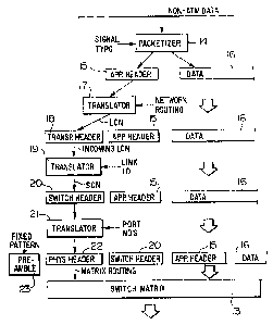
DETAILED DESGRIPTIO~ OF THE PREFERRED EMBODIME\T
As shown in Figure 1, input data in non-ATM formats
must Iirst be packetized into standardized ATDhi data
formais ire a for:~at converter 10, the output of which is
10' applied to a Witch peripheral 11 where certaiai packet.
headers are generated 2ror; the input packet. A
mtaltiplexer 1~' then generates and adds a "physical
header" to the daf,a packet before application to the
ghys~.cal switching matrix (or fabric? 13: The physical
15' header actually controls the matrik 13 to switch the
entire input data packet to a designated one of its
output ports.
_ ~~3~4~~
93120~a34 PCT/CA93/~ltDl t 8
The. pr oces s just. described is elaborated in fiom~
'_'. The inco.:inG noii-9TD:~f data, such as TD~1 or LAv
tlocal area networks data, is applied to packetizer 1.~,
which is configurable depending on the signal type at
p5 its input, and which is convenient) a repro~ra:-:,:~ab?w
data processor. The data packet Generated bv° the
gacketizei l~ comprises an application header l; and
data proper lr~. The application header, of course,
contain: a fixed nu:;ber or data bits specifying, a:i~ony
other things, where the data proper 16 is destined to.
translator l r havinG as its eontrollinj input network
routine instructions Generates fror:: the application
header 15 a traxisport header l~s which specifies a link
~onnec tion number i LC:~ i . t:p to this point. the
15 ~rocessinG of the input data and thereon generated
packet is part of the prior art. The transport header
l , grovidinb the ir~cominG LC~i, processed in translator
19 which retrieves the link ID to. provide a "logical"
scaitch connactian number (SCN) and encode it in a switch
header 2Q. A rurther translator 21 retrieves the
,oorresppnd,ino port numbers and converts the switch
hea-der ?0 to a tnon-logical > ghvsical header ??, the.
bats of which directly control the routing of the entire
W~ 93/20634 P~1'/CA93100118". ..,
~~~~4~~ -
-
packE.t through the actual switching r;~atriv 13. Just
before application to the matrix 13. the entire packet
has its preamble 23, which is used for clock recovery
and for packet identification where necessary.
p5 The introduction of the tlogicali switch connection
nu,;:ber SW as aai additional "layer" betwee~i the
t,physical~ layer necessary to control the matrix 13 and
the input ~variablen layers isolates the physical layer
froxa the variable layers; thus proc-iding for
10 architectural apd expansion flexibility. The
trancl.ators 17, 19 and 21. conE=eniently. are software
processed o~- periodically updated Iook-up tables.
Reierrino now to FZgure 3. once the data packet has
been scaitched- to one of the output ports of the switch
math°ia l3 it ,is checked by means of checker 2a, accepted
and stripped of its preamble 23 and physical header 22.
The switch header 20 is translated in translator 25 into
a lsecondl transport header 26, which is checked in
;: ; i checker, 2 i , and if accepted is stripped off . The
remaining application header 15 and data 1b are
"depacketized" in depacketizer 28. before being output
into the data stream.
' . ~ X3120634 ~ ~ ~ PC'I'/CA93/00118
Operatioai of the "layered" ATM switch core
interface svster,: will now be described with reference to
Figures ? to 5.
Before elaborating ar; the AT'H packet header lover:
05 ~t should be noted that preferably the logical switch
connection number is a conceptually °'flat" switch-wide
connection nur;~ber, the length of which in bits determine
m
the oiumber of possible simultaneous switch connections.
For exa:~:ple, an SCN of between 24 to 32 bits in length
would Permit about lb million to !~ billion simultaneous
connections .
As maW be seen f ro:~ the pre~rious discussion, the
actual user da ~ lb in the ATM packet is prefixed by
three Iavers of headers, preceeded b~~ a preamble to
provide link synchronszation. The preamble 23 comprises
l~$ bits of which 36 bats are repetitive 0101... clock,
and 1? bits axe a synchronizing pattern (011110t70010>.
APPLICATIO!u LAYER
The appla.cation layer, represented by the innermost
application header l5 is application specific. and is
di'O 93/20634 FC'1'/CA93/0011~'~
- 12 -
processed at the forr~~at conversion point. This. header
i~e;:.ains michan~ed fror.: end to end in a r:~ulti node
s~:i ached connection. In the _.framed data applications
~ such as f or LAI~. H1)LC ) , th~is~ layer ;rust specitical lv
OS contain at least coded infor.;,ation to indicate whpclu
part of the message frame i~ carried iii the present
packet; the first, the middle, the last, or the only
~.i.e. first and lasti part. In the case of the last or
only part, a b.-bit word would indicate the nu;:ber of
valid bytes in the packet, fror.; 1 to a maximur,:, which
for '~-bits is 64 data bytes.
It is preferred that the applecation specific
h a a d a r b a s a b j a c t t o f a t a r a i n t a r n a t i o a a l
standardization and, therefore, may ultirnatelv contain
~5 ;;:ore information, The application header may also not
have a fixed length for all applications; although iu
the present preferred embodiment a 7-bit application
header is used. The first bit indicates the start of a
r;;~ssage (SOM) (1), ar not the start of a message (0).
~ The following 6-bit field encodes a number n from: 0 to
5b. For n=O all data bytes are significant; for n=1 to
~n it means n bytes are significant end end of message
~~~J4~~
- 13 -
!EO~i~. Values of n above the size of the data field
could be used for special purposes. such as indicating
non-standard message types or the like.
LOGICaL BOLTING LAYER
C5 The second header layer sere=es routing, which
~.ncludes LCNs, and possible priority and route error
control features, wD~ere desirable. This layer, as it
applies to interaffice and access links is also subject
to international standardization. Sor.:e or all pai-t~. of
lp this header change fro:; link to link in a rnulti-link
connection: In the preferred switch impler:~entation,
access and trunk peripherals iMLX) process this header.
tdhile a fo~-r~ of this header may be usable in the switch
core. it is preferrable to separate this function tro;;:
lg routing of the packets through the switch itsel::. The
choice is then hos.- much of this header yin terms of bits
car bytes) wall have to pass throubh the switch
transparently, and how many of the bytes could be
;discarded, at the incoming peripheral and calculated anew
~t the outgoing peripheral, in order to conserve,
bandwidth through the switch.
w~ 9~i~a~~ ~crfe~93iam' ~ ~<. ,
~~.~~t~ ~~6~
° ~~ °
lr~ the switch core thi= layer will be occupied by
the Snatch i.;onnection lumber tSi.:~~ which will he deri~~ed
fror~: the incoming LCIi, in combinati-on with the physical
-.,, ,
lint: identit~~; it will be carried~transparently through
OS the core, and serves to generate the outjoing L.i.l.
PreEerrablv the SCI. being a switch wide logical number,
as also an interr,ediate address in the translation to a
physical r oute through the switch core f as opposed to
direct translation irorr~ Iink LCi~s which are phvsacally
1C bound to their links) in order to avoid logical to
physical translation to be done in the tpossiblv remote
link peripherals.
An SC?v oi, its equivalent is also needed at the
uec~iving end in order to distinguish multiple logical
7,5 calls orn the sa:~e link. and per;~it depacketization ai
nessages. In a prototype implemen ation of the present
invention the source field in the physical header tsee
belowl provides this function by having an 8-bit pseudo
~~~ field.
2p PHYSICAL ROt;TIIG LAYER ,
The third layer serves to route packets through the
'~ .~ ~ ~ ~ ~ 3 P~ri~~9~i~o~ ~~
'~ 9mzo63~ -
- 15 -
ci.it;:lv co:~ponents . Routing within :~I;Xes may or may not
use prefixed addresses within their equipment in place
of address bus signals. In the prior art (Banyan
network? routing on prefixed physical headers was one of
p5 the kew innovations to realize selfroutin~ networks.
especially in the context of cut through switching, i.e.
skiT.chinG the path as soon as the header was received.
t~ith the short packets of 9TD!~i, however, this is no
loryer a significant concerti, because the cost: of memory
for packet buffers is negligible, and the delay incurred
by storing a who~e packet before switching it diminishes
with Link speed (500 nanoseconds at lGbs).
how, howe~,rer, prefixing such physical headers
alloe~s the translation function to be moved to the
pexvipherv ox the switch, ultimately allowing foi~ a
migher capacity' matrix no r:~atter what the topology or
technc~lody .
In the experimental implementation, the physical
;routing lay,er'comprises a single-bit overflow flag to
indicata input buffer overflow, an ~-bit source field,
ypseudo SCL~ 1 , an Fi-bit destination field, and an 8-bit
CRC field (check byte.
~~ 93/2t~634 c . ~ PC~'tCA93td~fll 1~~.~ .., t
~ ~3~ 4~
- 16 -
The Source Field
The source byte or pseudo SCN,.identiiies the source
of the packet for depacketization~. In an idle packet it
aids in tracing the origin of idle packets for
p5 maintenance as well as serving to identify the source of
overload bits.
The Destination Field
The destination byte value ?55 they FF> is reserved
to indicate idle packets. Idle packets have valid cheek
bv~es and valid' source bytes. Otherwise the byte
ind~ntifxes the matrix port for routing the packet to
z~s destination.
Check F3yte Field
Unlike standard ATM header check on external links.
1,5 bhe purpose of the cheek byte in the internal switch
core format i.s not so much to prevent accidental mis
j .
delivery of packets due to line errors. but primarily to,
permit detection and subsequent maintenance of faulty
J 9312634 ~ ~ ~ ~ ~ Pi.'TlCA~3fOUll~
17
pat h . As such, its utility is enhanced if the check
byte covers all packet bits, including the data. For a
nu:ber of reasons, this byte appears in the header
t instead of at the end of the packet > which mean: that.
p5 the generation of the check byte mint be co:~.:pleted
before the packet is sent, i.e, another 1 packet delay.
In a variable length message fra;r:e application a
contemplated no additional time i~ lost, since this
dela~e is required anyway io determine if a packet is the
1Q last of a message frame before its header can be
completed.
The check byte may be calculated using RO~f table
lookup as shown in the check byte encoder of (figure
which is self-explanatory. This method allows
15 xmplernentation of ARC tcyclic redundancy checku as well
as other algorithms.
A check byte decoder is shown in Figure S, which is
self-ehplanatary.