Note: Descriptions are shown in the official language in which they were submitted.
CA 02133674 2000-OS-03
- 1 -
USING SUB-THRESHOLD UNIPOLAR PACING MARKERS TO IMPROVE THE
INTERPRETATION OF SURFACE EKG IN PACEMAKER PATIENT
BACKGROUND OF THE INVENTION
I. Field of the Invention
The present invention relates generally to cardiac
pacemakers, and more particularly to cardiac pacemakers having
a markers channel corresponding to and indicative of pacing
events of the pacemaker.
II. Background of the Prior Art
During unipolar and bipolar pacing, the pacing spike
may be hard to ascertain in the surface EKG. Thus, the
resulting electrocardiogram many times does not permit a
physician the ability to interpret the behavior of the implanted
pacemaker to evaluate the adequacy of the therapy that is being
delivered to the patient. At high pacing rates the analysis is
even more difficult, and the task of distinguishing between
atrial paced or sensed beats becomes sometimes formidable.
Another problem is to know why the pacemaker is delivering a
given therapy. Situations like "fall-back", "rate smoothing",
"sensor rate", "sensing during refractory", "upper rate limit
behavior", etc. are also very difficult to interpret from
surface EKG.
Prior art pacemakers typically incorporate telemetered
marker channels to help interpret pacemaker behavior, which
marker channels include coding generated concurrently by the
pacemaker during pacing. Presently, the marker channel is
sensed using well-defined external devices in combination with
telemetry functions built into the pacemaker. The marker
channel provides coded information indicative of the pacemaker
therapy currently being applied to the heart such that the
attending physician can intelligently compare the ascertained
EKG to the pacing therapy being applied by the pacemaker.
The ERGOS 03T"~ pacemaker offered by Biotronik provides
the ability to use a marker channel by sending below-stimulation
threshold pulses to the endocardial electrodes immediately after
pacing, which pulses can be recognized on
-2-
a surface EKG. Atrial sensed events are marked by a 30~cS
pulse that is emitted by the atrial lead. Ventricular
sensed events are marked by two sequential marker signals
emitted by the ventricular lead. The two ventricular
pulses have a spacing of 60 milliseconds, the first
denoting the moment of the sensed event. This particular
system has two main disadvantages. First, during committed
pacing situations issuing a sub-threshold pacing pulse to
the ventricular or atrial leads, a transitory conduction
block can occur. Issuing a supra-threshold pacing pulse
immediately thereafter could cause arrhythmias. Secondly,
this scheme only allows the pacemaker to send markers to
the surface EKG during sensing, and does not provide enough
resolution or time to code in several markers to indicate
situations like atrial sensed during PVARP, pacing due to
rate smoothing, ventricular ectopic sensing, etc.
Moreover, this scheme does not allow the pacemaker to send
markers simultaneously while pacing the heart. Finally,
this scheme does not allow generating supra-threshold
markers.
Several patents issued to Medtronic teach pacemakers
incorporating marker channels using well-known telemetry
functions. However, these devices require telemetry
equipment and receivers, and diagnosis needs to be
performed in the presence of an attending physician with
the appropriate equipment and telemetry receivers. Thus,
patients who feel irregularities in their pacemaker
operation only occasionally and intermittently at home
cannot be properly diagnosed by a physician for adjustments
to their pacemakers. Prior art pacemakers having marker
functions are taught in U.S. Patent 4,550,370 and U.S.
Patent 4,548,209 to Medtronic. Each of the devices taught
implements telemetry for transmission of programming codes
and to receive marker information from the pacemaker for
remote display and utilization. Similarly, U.S. Patent
595,009 and U.S. Patent 4,374,382 also to Medtronic teach
marker channel telemetry systems for medical devices, as do
2~.33~'~~
-3-
U.S. Patents 4,601,291 and 4,559,947.
To help understand the behavior of a pacemaker which
may be operating in an unknown manner, the physician will
provide the patient with a multi-channel holter monitor to
sense and store EKG signals over an extended time period,
such as 24 hours, while the patient is at home and away
from the physician's office. Unfortunately, prior art
diagnostic methods using holter monitors only sense and
store EKG signals from one or more locations of a patient's
body, which EKG signals are subsequently studied by the
physician. Consequently, the physician's ability to
diagnose the pacemaker behavior is limited to study of the
recorded EKG signals since telemetry of the marker channels
cannot be ascertained to help a physician understand the
pacemakers behavior.
OBJECTS
It is accordingly a principle obj ect of the present
invention to provide a pacemaker capable of generating
marker channels without using telemetry, which markers can
be recorded by the patient at home.
It is a further object of the present invention to
provide a pacemaker having marker channels which can be
easily sensed in the surface EKG of the patient.
Still yet a further object of the present invention is
to provide a pacemaker having marker channels which does
not create the possibility of producing a transient
conduction block that could lead to ventricular
arrhythmias.
Still yet another object of the present invention is
to provide a pacemaker having marker channels which can be
tuned to the bandwidth of the receiver such as an EKG
device, thus providing the possibility of encoding most of
the available markers to the surface EKG.
It is another object of the present invention to
provide a pacemaker having marker current/voltages
generated remote from the cardiac tissue and thus can have
an increased signal strength without risk of producing a
-4-
heart contraction.
Still yet a further object of the present invention is
to provide a pacemaker having a marker channel which can be
generated at any time including simultaneously during the
generation of pacing pulses.
SUMMARY OF THE INVENTION
The foregoing objects and advantages are achieved by
providing a cardiac pacemaker having an electrode disposed
proximate but isolated from the pacer can, wherein the
pacemaker has a marker code generator coupled to both the
pacer can and the electrode for generating marker codes
therebetween indicative of the pacemaker pulse generator
activity. Thus, the marker generator generates electrical
signals proximate the pacemaker can itself rather than
proximate cardiac tissue. The marker codes are generated
at a sufficient strength such that they can be detected by
surface EKG. Accordingly, a standard two-channel holter
monitor can be utilized by a patient at.home to sense and
store EKG on one channel, and sense and store a marker
channel on the second channel simultaneously. These
signals can be recorded over an extended period of time
such as 24 hours and then played back for the attending
physician at a later time for analysis. The marker
channels which are recorded simultaneously with the EKG
signal provide the physician valuable information on the
pacemaker therapy which was applied when the signals were
sensed. This marker channel information helps the
physician understand what therapy was being applied, and
why the pacemaker was providing a particular therapy.
More specifically, the cardiac pacemaker comprises a
pacer housing including a conductive pacing can. A first
endocardial lead having a first electrode is disposed
thereon. A second electrode is disposed proximate the
housing and is insulated from the pacer can. A pulse
generator is coupled to the endocardial lead for generating
pacing pulses. A marker generator is coupled to both the
pacer can and the second electrode for generating marker
~~3~~~4
-5-
codes therebetween. The marker codes are indicative of the
pace generator activity, wherein the marker codes are
generated at a sufficient signal strength such that they
can be detected by surface EKG. Since the marker codes are
generated proximate the pacer can itself, the marker codes
do not affect cardiac tissue and thus can be generated at
a sufficiently large signal and at any time, even during
pacing of the heart.
Ideally, the second electrode is disposed on the pacer
housing and is insulated from the pacer can, and may
comprise of a button electrode. The marker codes are
preferably generated at an electrical potential of between
5 millivolts and 5 volts. The first endocardial lead can
have a single tip electrode disposed in the heart ventricle
wherein the pacer can serves as a reference electrode.
Alternatively, the endocardial lead can be provided with a
ring electrode as well which is disposed in the heart
ventricle. Thus, unipolar or bipolar pacing can be
provided while generating a marker channel proximate to the
pacemaker can. The patient's body serves as the
transmitting medium conducting the marker codes between the
pacemaker and the patient's skin. Thus, conventional EKG
devices including portable two-channel holter monitors can
be implemented to sense and store the marker codes along
with the surface EKG.
BRIEF DESCRIPTION OF THE DRAWINGS
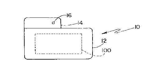
Figure 1 schematically shows a pacer apparatus having
a dual indifferent electrode apparatus;
Figure 2 schematically shows one embodiment of a dual
indifferent electrical apparatus for use in an implantable
heart pacemaker with a marker code generator disposed
between a neutral button electrode and the pacemaker can;
Figure 3 is a pictorial representation of a standard
two-channel holter monitor with two EKG leads adapted to a
patient's chest proximate the heart and pacemaker for
recording surface EKG signals and marker codes; and
Figure 4 is a pictorial representation of a standard
CA 02133674 2000-OS-03
- 6 -
two-channel holter monitor displaying two channels of
information, first, an EKG signal, and secondly, marker codes
which are simultaneously generated with the sensed surface EKG.
DESCRIPTION OF THE PREFERRED EMBODIMENT
Reference is made for additional information to U.S,
Patent No. 5,284,136, entitled "Dual Indifferent Electrode".
Referring to Figure 1 there is diagrammatically shown
a side view of a pacemaker apparatus 10 comprised of a
conductive metal can 12 and an insulating plastic top or header
14. Mounted in the top 14 and isolated from the metal can 12
is a button electrode 16. Contained within the can 12 is an
electronic circuit 100 which is explained in more detail below
and which comprises pacemaker circuitry including a marker code
generator.
Now referring to Figure 2, the circuit 100 is shown in
more detail. An endocardial lead 20 is connected to a pulse
generator 22 which is contained within the pacemaker 10. The
lead 20 includes electrodes 24 and 26 located within one of the
chambers of the heart 30. Electrode 26 may be, for example, a
stimulating tip electrode on a catheter-type lead disposed in
a ventricle while electrode 24 may be, for example, a ring
electrode disposed also in the ventricle. Insulator lead body
32 mechanically supports electrodes 24 and 26. A sensing
circuit 34 is electrically coupled to both electrodes 24 and 26
via sensing lines 36 and 38, respectively, and comprises of any
well-known sensing circuits for sensing and processing
electrical signals from the electrodes disposed within the
heart. Sensing circuit 34 is electrically coupled to pulse
generator 22 via line 40, wherein microprocessor based pulse
generator 22 generates pacing pulses to electrodes 24 and 26 in
response to sensing circuit 34 based on an algorithm programmed
therein. The pacing circuitry
discussed so far is well-known in the art.
Also comprising a portion of circuit 100 is a marker
code generator 44 which generates marker codes indicative
of the pacemaker state in response to pulse generator 22,
which pulse generator 22 is monitored via line 46. Marker
code generator 44 can comprise of any well-known marker
code generators, including amplitude or pulse-width
modulated devices, such as those disclosed and discussed in
the cited prior art, which prior art references are
incorporated herein by reference. For instance, one pulse
can be generated to indicate an atrial event, and two
pulses to indicate a ventricular event. Many algorithms
are possible and suitable with the present invention.
Button electrode 16 has a surface area typically on
the same order of magnitude as the surface area of ring
electrode 24 and is advantageously disposed on the plastic
top 14 of the implantable pacemaker 10. In the embodiment
of Figure 2, the button electrode 16 is connected via lead
48 to marker code generator 44. The conductive metal
pacemaker can 12 also serving as .an electrode is
electrically connected to marker code generator 44 via lead
50.
In contrast to prior art pacemakers which generate
marker codes transmitted via telemetry, the present
invention is comprised of a pacemaker generating unipolar
marker codes between an indifferent electrode 16 and the
pacemaker can 12. Thus, the marker codes are generated
proximate the pacemaker itself and remote from cardiac
tissue. These unipolar pulses are generated between the
can of the pacemaker 12 and the indifferent electrode 16 at
a potential exceeding the potential which could cause a
heart contraction. Further, the marker codes can be and
preferably are generated simultaneously as pacing pulses
are being applied by pulse generator 22. to electrodes 24
and 26 within heart 30. This provides the possibility of
encoding more markers due to the expanded time frame
available for sending markers. Further yet, this invention
_g_
provides the possibility of sending the markers to the
surface EKG wherein the pulses have a high energy,
preferably in the range of 500 millivolts to 1 millivolt.
Moreover, the generation of the pulses can be tuned to the
bandwidth of the receiver, and in the case of the surface
EKG, .1 to 100 Hz. These marker pulses can have different
shapes, amplitudes, durations and/or polarities to produce
different types of marks in the surface EKG recorder, which
marker codes are generated in such a way as to characterize
the behavior of the pacemaker therapy being applied to
electrodes 24 and 26.
A further feature of the present invention is that the
marker code generator 44 can only be activated when turned
on by the external programmer 52 operated by the physician,
such as using magnetic switches. Thus,~the physician can
selectively enable the marker code generator 44 for
diagnostic purposes such as when a standard two-channel or
multi-channel holter monitor is adapted to the patient and
taken home by the patient for monitoring over an extended
time period of say 24 to 48 hours. Thus, the pacemaker
battery life will not be appreciable reduced as the marker
code generator 44 is only selectively implemented by the
physician using external programmer 52.
Using the metal can of the pacemaker 10 along with an
indifferent electrode 16 to encode information in the form
of marker spikes in the surface EKG provides the feature of
sending information about the state of the pacemaker to the
physician while using the body as the link and the surface
EKG as the receiver. This approach has the advantage over
the prior art sub-threshold pacing spikes~since it does not
risk the possibility of producing a transient conduction
block that could lead to ventricular arrhythmias, as
discussed by KATZ (Physiology of the Heart, Raven Press,
New York, New York, 1992, pgs. 446-447). As discussed by
KATZ, transient conduction blocks could otherwise occur if
marker codes are generated proximate cardiac tissue because
the voltage-dependence of the heart's cells sodium
~~3~s~~
-9-
inactivation gates, a sub-threshold depolarization (like a
sub-threshold pacing spike "marker", being sent using the
unipolar configuration) followed by a supra-threshold
stimulus "normal pacing spike" will yield in an action
potential which rises more slowly than the normal action
potential and is of smaller amplitude. KATZ claims that
this voltage-dependence behavior will give rise to
conduction blocks that could produce ventricular
arrhythmias.
Another advantage of the present .invention is the
ability to tune bandwidth of the pacing spikes to the
bandwidth of the receiver i.e. EKG device, thus providing
the possibility of encoding most of the available markers
to the surface EKG.
By generating marker codes between the pacer can 12
and the indifferent button electrode 16 adjacent the
pacemaker 10, the physician is better able to interpret the
behavior of the pacemaker and thus evaluate the adequacy of
the therapy that is being delivered to the patient in view
of the marker codes generated simultaneously while pacing
the heart, which codes can be sensed in the surface EKG.
Even at higher pacing rates the analysis can be conducted,
and even the formidable task of distinguishing between
atrial paced or sensed beats becomes easy. Further, the
physician is able to ascertain why the pacemaker is
delivering a given therapy, including situations like
"fall-back", "rate smoothing", "sensor rate", "sensing
during refractory", "upper rate limit behavior", "mode
switching", etc. Thus, this invention is directed towards
providing a tool that will let the physician simplify the
interpretation of pacemaker behavior by the surface EKG.
Referring now to Figure 3, a commercially available
holter monitor 60 is shown connected to a patient 62 via a
pair of commercially available EKG leads 64 and 66. Each
lead 64 and 66 is electrically coupled to an EKG sensing
pad 68 and 70, respectively. EKG electrode 68 is coupled
to channel 1 of holter monitor 60, and EKG electrode 70 is
CA 02133674 2000-OS-03
- 10 -
connected to channel 2. Electrode 68 is disposed proximate the
heart for sensing surface EKG, and second electrode 70 is
disposed proximate pacemaker 10 surgically implanted within
patient 62 for sensing marker codes.
Referring now to Figure 4, holter monitor 60 is shown
having a two-channel display 74 visually displaying the first
channel 76 displaying the EKG sensed proximate the patient's
heart, and the second channel 78 displaying the marker code
spikes sensed proximate pacemaker 10. Each of the channels is
displayed in real time, simultaneously, such that the attending
physician can play back the recorded sensed EKG signals of the
patient while analyzing the marker codes, simultaneously, so
that the physician can understand what therapy was being applied
by the pacemaker when the particular EKG signal was sensed.
Since commercially available two-channel or multi-
channel holter monitors 60 are commercially available, no
further external equipment needs to be designed for application
with the present invention. Rather, monitoring equipment is
already available off-the-shelf and is ideally adapted to be
used with the present invention. Most pacemakers, including
demand-type pacemakers are ideally suited to implemented the
present invention of an additional indifferent electrode, such
as button electrode 16, along with the disclosed marker code
generator 44 electrically coupled to button electrode 16 and
pacemaker can 12. Again, any well-known marker algorithm or
coding scheme can be implemented in pacemaker marker code
generator 44.
-11-
While the present invention is shown implemented with
a bipolar lead; it is also to be recognized by one of
ordinary skill in the art that unipolar pacing could be
provided as well with a single tip electrode 26 and the
pacemaker can 12 serving as a second reference electrode.
The invention can also be implanted in a dual chamber
pacemaker. Thus, the present invention is ideally suited
for unipolar or bipolar pacing therapy.
Further, while an integral indifferent button
electrode 16 is shown disposed on pacemaker housing 10, it
is also to be recognized a separate lead could be used as
well extending to an indifferent electrode which is
disposed proximate pacemaker can 12, and thus limitation to
an indifferent electrode defined on the pacemaker can
housing is not to be inferred. Moreover, a second lead
extending to a second indifferent electrode could be
provided in place of pacemaker can 12 such that marker
signals could be generated therebetween proximate the
pacemaker and communicated via the patient's body to the
surface EKG. Accordingly, marker code signals generated in
reference to the pacemaker can 12 is not to be inferred as
well.
While telemetry is the preferred method for sensing
marker codes in the presence of a physician, the present
invention is ideally adapted for extended patient
monitoring wherein the marker codes can be sensed and
recorded at home at any time with the patient. Thus,
irregularities or concerns of the patient regarding the
pacemaker performing which cannot be duplicated or
ascertained in the presence of the physician can now be
recorded at home with the patient and' analyzed by the
physician at a later time. Consequently, the physician
w;.il not have to speculate how the pacemaker was
functioning when the patient was home and not in the
presence of the physician when using a holter monitor.
This invention has been described herein in
considerable detail in order to comply with the Patent
-12-
Statutes and to provide those skilled in the art with the
information needed to apply the novel principles and to
construct and use such specialized components as are
required. However, it is to be understood that the
invention can be carried out by specifically different
equipment and devices, and that various modifications, both
as to the equipment details and operating procedures, can
be accomplished without departing from the scope of the
invention itself.