Note: Descriptions are shown in the official language in which they were submitted.
~37~
HYDRAULIC DEVICE FOR SUPPLYING A HYDRAULIC DRIVING UNIT
BACKGROUND OF THE INVENTION
1. Field of the Invention
10This invention rela~es to a hydraulic device for
supplying a hydraulic driving unit in an injection molding
machine for processing synthetic materials comprising at
least one variable capacity pump, a main line extending from
the variable capacity pump to the driving unit, at least one ::
15 control valve arranged in the main line and adapted to :
determine a quantity and a pressure, a control conduit which : ~ :
connects a controlling mechanism of the variable capacity
pump with the main line downstream of the control valve, as
well as at least one pressure transducing means arranged for
20 transducing an actual pressure value downstream of the ~ ~ :
control valve, comparing means for comparing a nominal
pressure value and supplying a first correcting variable for
; the controlling mechanism in dependency of result of the
comparing means.
25 2. Descri~tion of the Prior Art ~:~
A hydraulic device of this kind for a hydraulic
7 9 ~
-
circuit of an injection molding machine for processing
synthetic ma-terials is known from German Patent 31 19 095.
In this hydraulic device the volume flow requirement is
adapted in an energetically favourable way to the consumer by
a pressure-current regulated variable displacement pump and a
control valve which is applied as adjustable ring spinner.
To this end a control conduit measures the pressure
downstream of the control valve, which leads the volume flow
to the consumer and supplies this value as input quantity to
the controlling mechanism. This input quantity is increased
by a preset operational pressure gradient, so that the
pressure drop is maintained constant via the control valve.
The pump is run with maximum power during the whole operating
time, so that even in those cycle parts in which no large
volume quantities have to be delivered, a large leakage
occurs in the pump region. Moreover the maximum speed of the
pump has to be in derivative action over the complete
operating time.
According to German Published Application ~ -
39 19 823 the hydraulic consumers in a hydraulic device are
connected with pumps, which are driven via A.C. servomotors. -~
Since no hydraulic control elements are used for regulation ; -~
between the pumps and the hydraulic consumers, these systems
work according to the principle of hydrostatic gearings. The
speed control is effected by variation of the motor speed. By
this measure a low-energy and noise-optimized operating
- 2 -
method of the consumers can be achieved. The disadvantage in
this device is the relatively expensive A.C. servomotors,
which is, however, consciously accepted.
SUMMARY OF THE INVENTION
It is an object of the invention so to design a
hydraulic device, which is of the kind described first
hereinbefore, that makes possible an energy saving control of
the consumers at a reasonble price.
That object is accomplished in accordance with
the invention in that the variable capacity pump is driven by
a rotary current motor, which is connected to a current
source, wherein a speed of rotation of the rotary current
motor is regulable via a frequency converter arranged between
the current source and the rotary current motor.
Extensive tests in practical operations have ~ ;
shown that the no-load loss of variable displacement pumps
decreases noticeably at low speed of the pump. In zero
lifting operation, i.e the pump delivers only a low flow rate
in order to maintain the set system pressure, the no-load
driving power at 500 revolutions per minute is reduced by
approx. 50%. By actuating a variable displacement pump via a
variable driving speed of rotation it is made possible to
take advantage of the reasonable price of such a variable
displacement pump and nevertheless to save energy due to the
variation of the driving speed of rotation.
Contrary to thé expensive rotary current servo-
motors the driving speed is controlled by a cheap standard
~ 7 ~ a
current synchronous motor, the speed of which is controlled
by a frequency converter. The required nominal value for the
speed is calculated by the superset control from the
programmed speed profiles and the actual pump pressure value.
During the injection operation the power consumption of the
motor is reduced by approx. 20 to 35% at average shot
quantity.
Contrary to a rotary current servomotor the
pumping capacity cannot be reduced to zero, however, this is
not absolutely necessary, since always a minimum pressure has
to be kept up for the hydraulic system.
BRIEF DESCRIPTION OF THE DRAWING
Figure 1 is a schematic representation of the
hydraulic circuit.
Figure 2 is a schematic representation of an -
example of an injection cycle.
DETAILED DESCRIPTION OF THE PREFERRED EMBODIMENTS
The invention will now be described in more
detail by example with reference to the embodiments shown in
the Figures. I~ should be kept in mind that the following
described embodiments are only presented by way of example
and should not necessarily be construed as limiting the
inventive concept to any particular physical configuration.
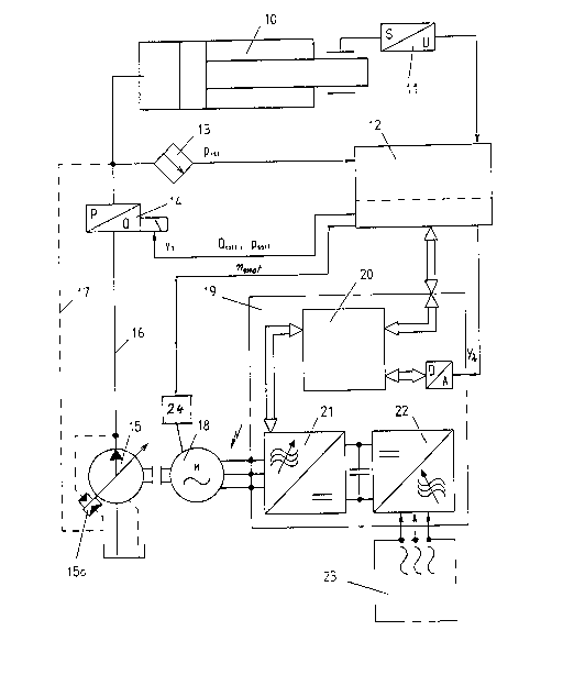
Figure 1 shows a driving unit 10, for example a
piston-cylinder unit of an injection molding machine for
processing synthetic materials. This driving unit is supplied
- 4 -
with hydraulic fluid by a variable capacity pump 15 via the
main line 16 and a proportional flow control valve controls
the flow of the hydraulic fluid to the driving unit 10. This
valve 14 is adjusted by a control 12 via a first correcting
5 variable y1. This first correcting variable y1 corresponds to ..
preset nominal values regarding the quantity (Q8011 ) and the
pressure (PAO11 ) . The actual position of the driving unit 10
is captured by a section voltage transformer 11, which also
transmits a corresponding signal to the control system 12.
The pressure downstream the control valve 14 is
recorded as actual pressure value by the control conduit 17
and is supplied to the controlling mechanism 15a of the
variable capacity pump 15. At the same time the pressure
upstream the control valve 14 is recorded, so that due to
this two values a constant operational pressure gradient can
be maintained provided the variable capacity pump is adjusted
with a preset value. The variable capacity pump can be
engaged in closed or open loop. This allows to quickly
follow-up the whole system to varying conditions. The
pressure in the main line 16 downstream the control valve 14
is also transmitted via a pressure transducer 13 as actual
pressure value Pi~ t to the control. The variable capacity
pump 15 is driven by a rotary current motor 18 or a three-
phase current motor. This rotary current motor is connected
to a current source via a frequency converter 19, which
modulates the current frequency in a certain region, usually
~;
;x: ~ :
7 ~ ~
between 10 and 50 Hertz. The control system 12 is in
communication with the controller 20 of the frequency
converter 19. Due to preset values for the injection cycle or
parts of an injection cycle a second correcting variable y2
is delivered from the control system 12 via the digital-
analog-converter to the controller 20. The controller 20 ~-
transmits a corresponding instruction to the frequency
regulator 21 for the rotary current motor 18. The frequency ~ -
regulator 21 itself is provided with energy directly from the -
switch cabinet 23 via three phases and from a current source.
The switch cabinet 23 is connected with the frequency
regulator via an intermediate circuit 22, which can also
serve as capacitive buffer when the motor speed is reduced -~
or accelerated.
Basically the function principle of the hydraulic
device is that the maximum pumping capacity, depending on the -
preset values for the respective injection cycle, is reduced
to the maximum capacity required for the individual injection
cycle or for a part of this cycle, as can be seen from -~
Figure 2. The frequency converter takes action in this part.
The pressure changes required afterwards i.e. during the
individual sequences are largely realized by following-up the
operational pressure gradient in a way as described in German
Patent 31 19 095. Figure Z represents an example of an
injection cycle in which the nominal value for the quantity
Q8011 corresponding to the first correcting variable yl and
nmO t corresponding to the second correcting variable y2 are
outlined over the time. In addition the values Qmax and nmax
corresponding to the maximum capacity are laid off, too. The
numbers outlined on the coordinate stand for the individual
parts of the injection cycle. They mean:
~ ;
1 close mold
2 advance plasticizing unit
3 injection
4 dwell pressure phase
proportioning
6 open mold
7 ejection movement
8 retract plasticizing unit
If the corresponding moto~ speed nmOt for each at ~-
least required maximum power drops below the minimum value,
the remaining regulation is as far as possible controlled
in cooperation between the control conduit 17 and the
controlling mechanism 15a. Whereas for the most parts of an
injection cycle at least low savings compared with the
maximum power of the pump are apparent, it is very clear that
for instance during the proportioning 5 and during the dwell
pressure phase 4 the motor speed nmo t iS considerably reduced
resulting in a correspondingly lower energy consumption.
In order to increase the dynamic of the whole
7 ~ a
system in case necessary and thus possibly increase the
influence of the second correctiny variable y2 on the total
sequence even more, an engine speed sensor 24 can caliper the ~ :
number of revolutions of the rotary current motor 18 and
supply this number as input guantity to the control, so that
the number of revolutions is cascadely controlled by the ~ - -
frequency converter. In this moment the importance of the
first correcting variable yl decreases even more.
The variable capacity pump 15 is also
superimposed by a rotary current motor regulable with regard
to its speed in form of a cascade control.