Note: Descriptions are shown in the official language in which they were submitted.
21338~1
IMPROVED FLOW REFRIGERATION VALVE
BACKGROUND OF THE INVENTION
1. Field of the Invention
The present invention relates generally to valves for use in the fluld
circuits of refrigeration and air-conditioning systems and, more particularly, to
5 compressor valves and line servlce valves.
2. Discussion
Compressor valves and line service valves have been commonly used
in refrigeration system fluid circuits to direct the flow of refrigerant through the clrcuit
or retain the charge of liquid or gaseous refrigerant while Isolating a portion of the
10 circuit to facllitate the repalr and/or replacement of system components or to perform
general system maintenance. i-~amples of such valves are illustrated in prior art
Figures 1 and 2. Figure 1 shows a typical valve, such as one that is commonly made
out of brass or steel which is used on compressors in ihe refrigeration and air-
conditioning industry. The valve 100 includes a primary stem operator 102 that is
15 disposed for linear movement within a valve body 104 by a threaded engagement,
indicated at 106. Packing, generally Indicated at 108, seals the valve 100 at the
primary stem operator 102 while still allowing it to be rotatable in the valve body 104.
At one end of the stem operator 102 is a globe-type plug or closure element 110 that
is operable to completely block oH a fluid passage 112. The primary stem operator
20 102 is linearly positionable between an opened position (as shown in Figure 1) and
a closed position (not shown) when rotated. In the opened position, the closure
element 110 is backseated against the valve body 104 at location 114 and fluid is
capable of flowing through the valve 100. In the closed position, the closure element
.. . ~ . ,
. ~ ., ~. . . :
.. ~ .. -: ~. .:
2133~1
. ,~'
110 is advanced into fluid passage 112 and seated against valve body 104 at location
116. In this position, nuid flow through the valve 100 Is prevented.
Figure 2 deplcts a cast Iron compressor valve whlch Is gen~rally used
with fluid line diameters greater than or equal to 2 1/84. Very slmilar to the other
5 compressor valve described above, the cast Iton vaive 120 lncludes a primary stem
operator 122 that Is disposed for linear displacement wlthln a valve body 124 by a
threaded engagement 126. Located at one end of the primary stem operator 122 is
a globe-type closure element 128 which is operable to block off a fluid passage 130
through the valve. In the opened position, the closure element 128 is backseated10against the valve body 124 at locatlon 132 and fluid Is capable of flowlng through the
valve 120. In the closed positlon, the closure element 128 is advanced Into tluid
passage 130 and seated against valve body 124 at location 134. In this position, fluid
flow through the vaive 120 is prohibited. The closure element 128 in the cast iron
compressor valve 120 typically includes a plastic seat 136.
15As shown in Figures 1 and 2 and described above, globe-type
compressor and line seNice valves commonly Include a threaded, reciprocating
primary stem operator which serves to linearly displace a closure element within the
fluid passage of a valve body between an opened and a closod position. When the
valve is in the opened position, as is illustrated in Figures 1 and 2, the closure element
20 Ig still located In the valve's fluld passage and, therefore, in the fluid flow stream
Because of this inherent design feature, blockage or Interference within the fluld
passage Is created and, the fluid flow through the valve becomes turbulent, resulting
in an increased pressure drop across the vaive. The pressure drop, in turn, reduces
the efficiency of the valve by allowing a significant amount of energy to be lost from
25 the refrigeration circuit. Consequently, thls energy loss presents a design constraint
that must be addressod by r~frigeratlon and alr~ondltionln~ system deslgners and
~1338~
engineers as they develop refrigeration and air-conditioning systems. Often, to
compensate for the energy loss, system designers and engineers specify larger, over-
sized compressors which exceeci the thermodynamic requirements of the refrigeration
system application. The use of such overslzed compressors Is Ineffllcient and a wasta
5 of energy.
In the past, the refrlgeration and alr-conditioning Industry has tolerated
the occurrence of flow turbulence, pressure clrop and the resulting energy loss whic
has been observed across refrigeration valves of the compressor and line service
type. However, due to the increasing awareness of energy conservation and the
10 attendant need to design and davelop more energy effficient refrigeration and air-
conditioning systems, it has become desirable to improve upon the efficiency of these
types of refrigeration valves by reduclny or eliminatlng the flow turbulence, pressure
drop and associated energy loss experiericed with them. In a typical application, for
example, a series of compressors may be utilized in a refrigeraUon system such as the
15 refrigeration section of a grocery store or supermarket, or the air~onditioning system
of a large building. Improving the efficiency of compressor valves may enable fewer
compressors to be used In a given application or allow a given number of
compressors to work for shorter per70ds of time, or less than peak output thus saving
not only significant amounts of operating costs in the form of electrical energy, but
20 also significant equipment acquisition, repair and maintenance costs as well.
Further, it has been considered equally desirable that any improved
efficiency valve maintain the ability to achieve a positive shut~ff or seal as found in
prior art globe-type valves wherein tha application of a torque is translated into linear
displacement. Presently, refrigeration valves having enhanced llow characteristTcs do
25 not offer the feature of enhanced sealability.
,,. . .~. ~. . .
: -, . ~ - .
.; - ~ - ~ . .
2133~1
: -?
it is, therefore, an object of the present invention to provide a valve for
use in the fluid circuit of a refrigeratlon or air-condltlonlng system, such as a
compressor or line servlce, that Is slgnificantly more energy efficlen1 than present
refrlgeration valves by mlnlmizing or substantially ellmlnatlng turbulence In the 11uld
5 flow path through tha valve and the resultlng pressure drop and energy loss. it Is an
additlonal object of the present invention to provlde such an improved efficiency valve
that also effectuates a posltive seal.
~ ~ . A
1338~1
SUMMARY OF THE INVENriON
Accordingly, the present Invention Is dlrected to a valve 10r use In the
fluid circuit of a refrigeratlon or alr-conditlonlng system, such as a compressor or llne
servlce valve that Is significantly more energy effclent than present reklgeratlon valves.
5 The valve incorporates a rotary ball member havlng a fluid passage slze that Is equal
to or slighUy greater than the slze ot the fluld line that it Is Intended to seNice. The
valve Is actuated by a ball stem that rotates through approxlmately 90 to open and
close the vaive. A lock stem is aligned on an aiternate axis 1rom the ball stem that Is
preferably collinear wlth a fluid llne. A plunger Is positioned withln the vaive to center
10 the rotary ball member and insure that it Is properly allgned wah respect to fluld llne
connectors. Locator indentatlons and a groove In the rotary ball member operate to
engage and guide a head of the plunger which is biased into engagement wlth the
rotary ball member by a compression spring. When the lock stem Is In the locked
posltion, it effectuates positive sealing force between the rotary ball member and an
1-5 annular ball seal and therefore makes the valve extremely sultable for fluid circuits
such as refrigeratlon or air-condltlonlng systems whereln posltlve sealing against
- leakage of refrigerant Is an Important conslderatlon.
The re1rigeration vaive o1the present invention substantlally reduces or
ellminates the 1iow turbulence to thereby Improve the energy effciency over the prlor
20 art compressor and line service valves. The vaive thus contrlbutes to the overall
officiency increase In the refrigerathn or air-conditioning system as a whole. The
resultant enhanced flow effciency of the present valve invention wlll permlt greater
refrigeration and air-conditioning system performance and improved energy efficiency
ratlngs. This will, in turn, lower the system acquisition, operatlon and maintenance
25 costs by virtue of the ability to reduce energy consumption, reduce the number of
S
.
~33~
. ~
compressors required or utilize smaller slzed compressors and other system
components.
.
'21333S~
BRIEF DESCRIPTION OF THE l~RAWINGS
The various features and advantages ot the present invention will
become apparent to one skilled In the art upon reading the followlng descrlption of
the preferred embodiment In which:
Figure 1 depicts a transverse cross-sectlonal view of a flrst prlor art
compressor or line service valve In the opened position, of the type for use in the fluld
circuit of a refrlgeration or air-conditionlng system;
Figure 2 Illustrates a transverse cross-sectional view of a second prior
art compressor or line service valve in the opened position, of the type for use in the
fluid circuit of a refrigeration or air-conditioning system;
Figure 3 shows, in the opened position, a transverse cross-sectional
view of an improved flow refrigeration valve having a positive shut-off feature of the
type for use in the fluid circuit of a refrigeration or air-conditioning system and
constructed according to the principles of the present invention;
Figure 4 illustrates a transverse cross-sectional view of the improved
flow refrigeration valve of Figure 3, in the closed position;
Figure 5 is a plan view of a rotary ball member for the Improved flow
refrigeration valve of Figure 3;
Figure 6 is a transverse cross-sectional view of a plunger for the
improved flow refrigeration valve of Figure 3;
Figure 7 is a plan view of the plunger of Figure 6;
Figure 8 Is an enlarged detail view, partially In cross-section, of the
rotary ball member of Flgure 5 and the plunger of Figure 6 as the Improved flow
refrigeraUon vaive of Figure 3 Is being rotated between an opened and a closed
pos-ition; and
2~33831
,, ,, . i
Figure 9 iilustrates a transverse cross-sectional view of an improved
nOw refrigeration valve having a posltlve shut-off feature of the type for use In the fluld
circuit of a refrigeration or alr-conditionlng system and constructed according to the
principles of an alternate embodiment of the present Invention.
, ~, . ~ -
21338~
DESCRIPTION OF THE PREFERRED EMBODIMENT
H should be understood from the outset tha~ whlle the drawlngs and
following discussion relate to a partlcular embodlment ot the present Inv~ntlon, thls
embodiment merely represents what is presently regarded as the best mode of
5 practicing the Invention and other modificaUons may be made to the particular
embodiment wlthout departing from the spirit and scope of the invention.
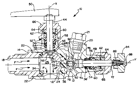
Reterring now to Figures 3 through 8, an improved nOw refrigeration
valve 10 of the present invention is shown. As Illustrated In Flgure 3, valve 10 Is In the
opened position to accommodate the unrestricted flow of fluld therethrough. While
10 the flow dlrection of tluid through the valve has been indicated by flow arrows F for
purposes of discussion, it should be understood that use of the present Inventlon is
not in any way limlted to fiuld nOw in any partlcular dlrection. in contrast to Figure 3,
Figure 4 shows valve 10 in the closed position where the positive shut-off feature of
the present invention is engaged and tluld 11OW through the valve 10 Is prohiblted.
15As shown in Figures 3 and 4, valve 10 generaliy Incorporates a body
section 12 and tail section 14. Valve 10 body section 12 and tail section 14 each
include a fluid line connector portion 16 and 18, respectively, which serves to connect
` ~ the valve 10 to the fluid circuit of a refrigeraUon system (not shown). Fluid line
connector portions 16, 18 may be compatible with any of a varlety of standard fluld
20 line connectlons, Including face seai nttings, flange fmings, flare fittings, pipe fittlngs
and soldered fittings, to narne a few, all of which are well-known in the industry. Body
section 12 also includes a service port 20, having a pipe plug 21, that allows ready
access to the fiuid clrcult to which the vaive 10 is connected, such as for the addUion
or withdrawal of refrigerant to the system. Body secUon 12 and tail secUon 14 ot valve
25 10 are alignably connectable such as by a threaded engagement, generally indicated
at location 22, to form a unttary valve body after the InstallaUon and ass~mbly of the
~133~
valve's 10 components has besn completed. A sealed connection between body
section 12 and tail section 14 may be achleved by sultable known methods, such as
welding, brazing or the llke. Aithough the body of valve 10 has been described as
having a multi-component construction Including body section 12 and tall sectlon 14,
it should be apprectated that the body of valve 10 may also be manufactured as asingle component.
Aiso shown in Figures 3 and 4, a generally spherically-shaped closure
element or rotary ball member 24 is disposed between body section 12 and taii
section 14. ~iotary ball member 24 Includes a nlnety degree (9OD) port or tluid
passage 26 that is operable to communlcate with both fluld llne connector portions
16 and 18 when valve 10 is In the opened posltion, as shown in Flgure 3. Fluid
passage 26 is sized to be substantially equal to or slightly greater than the size of the
fluid lines that valve 10 Is Intended to servlce. Shown in greater detall in Figure 5,
rotary ball member 24 Includes a first or opened locator Indentatlon 28 and a second
or closed locator indentation 30. In the preferred embodiment, the locator
indentations 28 and 30 are conical in shape and spaced apan approximately ninetydegroes (90~. A shallow channel or V-groove 32 extends circumferentially in the
` surface of rotary ball member 24 between locator indentiations 28 and 30. Rotary ball
member 24 also Includes a slot 33 for recelving stem head 48 of ball stem 44, as will
be turther described herein.
While in the preferred embodiment body sections 12 and 14 and rotary
ball member 24 of valve 10 are manufactured In a machining operaUon from brass, it
is contemplated that other suitable preclsion valve construction materials such as
steel, molded plasUc, or the like could also be utilized.
An annular ball seal 341s disposed wlthln tall sectlon 14 adjacent rotary
ball member 24. Ball seal 34 serves to provlde a seat agalnst whlch rotary ball
,~'.~- ' ` ' ' '
~133~31
member 24 may be positlvely sealed as shown In Figure 4. Balî seal 34 may be made
of any suitable material, carbon-filled teflon being one example. Disposed within body
section 12 on an opposite slde of rotary ball member 24 from ball seal 34, a plun~er
36 acts to center rotary ball member 24 withln body 12 so that nuld passage 26 Is
properly allgned wah fluld line connector portions 16 and 18. Plunger 36, shown In
more detail in Figures 6 and 7, has a locator head 38 and a plurality of fingers or
extension portions 40 each havlng a pad 42 for engaglng the surface of rotary ball
member 24. Pad 42 may be suitably contoured to better engage the generally
spherical surface of rotàry ball member 24. Flgure 7 illustrates plunger 36 as including
four extension portions 40, that are arranged in opposite pairs and are located on
perpendicular axes so that each extension portion 401s spaced approxlmately nlnety
degrees (9OD) apart. However, a plunger 36 for use with the present Invention may
employ any suitable number of extension portions 4û which may be more or less than
four. Plunger 36 may further be provtded in various configurations which provide fluid
communication between service port 20 and the fluld system lines to which valve 10
Is connected when servicing valve 10. Locator head 38, which protrudes from the
center of the plunger 36, has a tapered or conically-shaped surface 39 which is
operable to engage locator indentations 28 and 30 and groove æ In rotary ball
member 24 as will be further descrlbed hereln. Extension portlons 40 and locatorhead 38, in comblnaUon with locator indentaUons 28 and 30 and groove 32 serve toenable plunger 36 to center rotary ball member 24 within body section 12 and align
fluid passage 26 with fluid line connector portlons 16 and 18. Plunger 36 Is preferably
manufactured from a strong, flexible materiai that is able to maintain its form, M and
function over a wide spectrum of operating temperatures, ranging from approxlmately
minus for~y degrees Fahrenheit (~F) to about four hundred degrees Fahrenheit
(400DF). Thermoplastic polymer matertals have proved suitable for thts appltcation.
1 1
., ;, .. ,~, . ., . ., . .. , -. - , . . --
~-` 2133~
An alternate two-piece plunger 36' embodiment for use In the valve 10
of the present Invention Is shown in Fl~ure 9. In this arrangement, locator head 38'
and extenslon portlons 40' are tormed as separate components. As shown, locator
head 38' extends through an aperture 92 and counter-bore 94 In extenslon portlon~
40'. The locator head 38' is operable to sllde through aperture 92 thereby allowlng
locator head 38' to be IndependenUy biased agalnst rotary ball member 24 by
engagement wlth sprtng 82 at prolectton 95. Included with this alternate plunger 36'
destgn, stem head 78' has a reduced diameter shoulder 96 which Is larger than the
apenure 92 but smaller than the counter-bore 94. The components of plun~er 36'
may be manufactured from a thermoplasUc materlal, or aiternately, if a harder plunger
36' ts desired, the locator head 38' may be manufactured from a metal, such as brass,
alumtnium or steel, for example.
A primary stem operator or ball stem 44 is Included in valve 10 and Is
operable to be moved between, and therefore provtde valve 10 wtth, a first or opened
posttion and a second or ciosed positton as shown tn Ftgures 3 and 4, respectively.
Preferabiy, ball stem 44 ts operable to rotate rotary ball member 24 through
:~ .
approxtmately ntnety degrees (90) of travel to open and close valve 10. Ball stem 44
extends along a first axts X and Is rotatably supported in body sectton 12 at a first
:~ .
neck portton 46. A stem head 48 located at a first end of ball stem 44 engages slot
; ~ 20 33 tn rotary ball member 24 for rotattng ball member 24 as ball stem 44 ts rotated.
The opposite end of ball stem 44 is connected to a first operattng or ball handle 50.
Packtng, generaliy indicated at 52, ts located between neck portton 46 and ball stem
44 and serves to seai neck portion 46 and Ulerefore body sectton 12 at ball stem 44
- whtle sttll allowtng ball stem 44 to be rotatably supported thereln. Packtng 52 tncludes
an O-rtng 54 that ts held tn place by a flange 55 on body section 12 and a pack
washer 56, a pack rlng 5B that is prcferably constructed of a thermoplastlc materlal,
12
.
.. -
..
~` 2133~
a pack gland 60, a belleville washer 62 and a compression ring 64. A pack nut 66 Isthreaded onto neck portlon 46 of body sectlon 12 and acts to secure packlng 52
within valve -iO. An anU-frktion ring 68 Is disposed Intermediate nange 55 and an
annular lip 70 that Is provided on ball stem 44 Just above stem head 48. The
5 preferred packing 52 arran~ement descrlbed above ralses the valve 10 to a zero-
leakage system. However, altemate packlng arrangements, such as an arrangement
employing a single 0-rlng and a seal cap whlch Is slmpiy crimped over the top of the
neck portions 46, 74 ot the body sectlon 12, for example, may be used with valve 10
if deslred.
A secondary stem operator or lock stem 72 is also Included In valve 10
and is operableto provlde valve 10with an unlocked and a locked or positlvely sealed
position, as shown in Figures 3 and 4, respectively. In a first or unlocked position of
lock stem 72, rotary ball member 24 may be freely rotated between the opened andclosed positions, and in a second or locked position of lock stem 72 rotation of the
15 rotary ball member 24 is prevented and a positwe engagement or shut-off is
effectuated between the rotary ball member 24 and the ball seal 34 to enhance the
sealability of valve 10 and prevent the passage of re*igerant or other fluid
therethrough. Lock stem 72 Is rotatably supported In body section 12 at a secondneck portion 74 and Is allgned along a second axis Y that is preferably collinear with
20 fluid line connection portion 18. RotaUon of lock stem 72 Is translated into linear
displacement of the lock stem 72 within body secUon 12 and along axls Y by meansof a threaded engagement, generally indicated at 76, between lock stem 72 and body
section 12. Preferably for smaller vaives 10, lock stem 72 may be posiUoned between
- the locked and unlocked positions with a totai rotaUon of about one hundred eighty
25 degrees (180~). However, it Is recognized that severai factors Including the size of the
valve 10, the amount of torque requlred to ef~ectuate a positive seal In the valve 10,
,
13
-- 2~33~
and the pitch of the threads 76 that connect lock stem 72 and body section 12,
determine the total rotation of the lock stem 72 between the bcked and unlocked
positions. A flrst end of lock stem 72 Includes a stem head 78 havlny an apenure or
pocket 80. A compresslon sprln~ 82 Is disposed withln pocket 80 and Is blased
between lock stem 72 and plunger 36. At the opposite end of lock stem 72 a second
operatlng or lock handle 84 Is removabiy connected. Engagement between matlng
splines on lock stem 72 and lock handle 84, generally Indlcated at 86,1s secured by
screw 88. It should be noted that In larger valves 10 the lock stem 72 may
Incorporate a square drlve Instead of lock handle 84 In order to facilitate the
generaUon of greater amounts of torque, which ate typically required to effectuate a
positive seal In larger valves 10. As previously described with respect to ball stem 44,
Iock stem 72 also Includes packtng 52, whTch comprlses O-ring 54, pack washer 56,
pack rlng 58, pack gland 60, belleville washer 62, compresslon rlng 64, and pack nut
66. However, because lock stem 72, unlike ball stem 44, Is operable for both
rotational and linear displacemént within body secUon 12, packing 52 for lock stem
72 includes a second pack washer 56'. Again, packing 52 serves to seal off second
neck portion 74 and therefore body section 12 at lock stem 72 while still allowing lock
stem 72 to be rotatable and linearly disp!aceable wlthln the body section 12.
The improved nOw refrigerant valve 10 of the present invenUon may be
manufactured to accommodate varlous standard tluld llne skes and yet still
Incorporate many standard components. For exarnple, all the components describedabove, including the body and stem operator assemblies wRh the exception of rotary
ball rriember 24, could be standardked. In thls case, different rotary ball members 24
havlng variously sked fluld passages 26 together with 11uld line adapters (not shown)
~; ~ 25 capable of adapUng the varlous sked nuld llnes to be connectable wlth standard nuld
line connection porlions 16 and 18, would be all that was necessary to modify provide
14
, . ~ . ~ , . . .....
A ',, `~ ' '~; . . . .
I"~ ". ' '' '' '
'';" ~ " '
21333~3~
-
valve's 10 for use with different fluid lines. Because the body 12 can be a sln~le slze
and yet be adapted to servlce a varlety of the tluld llne slzes or diameters, the valve
10 can be economlcally produced. In additlon, the valve 10 can be readily produced
with a variety of standard ~footprints~, such as a two-boit tlange surface found on
5 typical compressor valves or any of the otherfiuld line connectlons commonly utillzed,
which facllitates the abllity to retro-m the present valve Inventlon Into existln~ nuld
circults.
With reference againto Figures 3 and 9, the improved 11OW refrlgeraUon
valve 10 of the present InvenUon Is Illustrated in the opened, unlocked posaion. In thls
10 posltion, the unobstructed and therefore substanUally lamlnar flow of fluld Is allowed
through valve 10, as is exemplified by nOw arrows F. In the unlocked position, rotation
of rotary ball member 24 between the opened and ciosed posltions is not prohibited.
~ - .
As shown, ball handle 50 and ball stem 44 are oriented in a first or opened position
so that fluid passage 26 of rotary ball member 24 is in communication with both fluid
15 line connector portions 16 and 18, and lock handle 84 and lock stem 72 are oriented
in a first or unlocked posfflon so that no shun-off force Is belng applied agalnst the
rotary ball member 24 to positiveb seat the rotary ball member agalnst ball seal 34
In the opened, unlocked posiUon, locator head 38,38' of plunger 36,36' fully engages
opened locator IndentaUon 28 on rotary ball member 24 by vlrtue of the blas ot
20 compresslon spring 82. Aiso, lock stem 72 is seated In a backseat position such that
stem head 78, 78' is situated agalnst body section 12 as shown at 90, thereby
weating a clearance between the stem head 78 and the plunger 36. Although
compression spring 82 remains nomlnally blased between lock stem 72 and plunger
- . -
36, 36' and Is oper~ble to malntaln engagement between locator head 38, 38' and
25 locator Indentation 28, the clearance dlmenslon that resuits when lock stem 72 Isbackseated Is smaller than the depth of locator indentaUons 28 or 30, thus making It
. ~ ;
213 3 ~ ~1
physically impossible for locator head 3B, 3B' of plunger 36, 36' to becom~ 1ully
disengaged from either locator indentation 28 or 30 or groove 32 when the lock stem
72 is In the unlocked posltlon.
Turning now to Flgure 4, valve 10 Is shown In the clos~d, locked
position. In thls position, rotary ball member 24 sealingly prevents the flow of nuld
through th~ e valve 10 and rotaUon of rotary ball member 24 between the opened and
closed posltions is prohiblted. As shown, ball handle 50 and ball stem 44 are In a
second or ciosed posaion so that fluid passage 26 of rotary ball member 24 is unable
to communicate with nuid line connector portion 18. Aiso, lock handle 84 and lock
stem 72 are in a second or locked position such that a positive shut~ff is created
between rotary ball member 24 and ball seal 34. In the locked position, locator head
38 of plunger 36fully engages closed locator Indentation 30 of rotary ball member 24.
In addition, lock stem 72 is advanced to a position whereby the clearance between
stem head 78 and plunger 36 Is elimlnated so that stem head 78 is brought Into
contact with plunger 36. When locked, a positive shut-off force to seat rotary ball
member 24 agalnst ball seal 34 is generated by stem head 78 and by compression
spring 82, which is now substantially fuliy compressed bet~,veen lock stem 72 and
plunger 36. Aithough Figure 4 illustrates that the vaive 10 is ciosed when in the
Iocked position, it should be appreciated that the valve may be locked In either the
opened or ciosed posltion.
With reference to Figure 9, the operation of the aiternate plunger design
36' in the locked position can be understood. In the iocked position, locator head 3B'
of plunger 36' fully engages ciosed locator indentaUon 30 of rotary ball member 24.
Aiso, lock stem 72 Is advanced to a position so that shoulder 96 of stem head 78' is
brought into contact with a seat 98 on locator head 38' of plunger 36'. When locked,
a positive shut-offforce to seat rotary ball member 24 against ball seal 34 Is generated
16
" ,",, .. ,, ., " . . ., ,. .. ,~ ~ ., ,, :, '. .` ' ' : ` '
3 ~
by stem head 78' and by compression ~pring 82, which is now substantially fully
compressed between lock stem 72 and plunger 36'.
Figure 8 illustrates In enlarged detail valve 10 as the rotary bsll member
24 is being moved between the opened and closed posHions. As descrlbed above,
5 In the unlocked position, a clearance exists between stem head 78 ot lock stem 72
and plunger 36, whereln compression spring 82 Is oniy nominally blased, and the
rotary ball member 24 may be rotated to open or close the valve 10. As rotary ball
member 24 is rotated from the opened to the closed position, for example, locator
head 38 of plunger 36 Is forced from Its full engagement wlth opened locator
10 indentation 28 and into full engagement with groove 32. Again, it should be noted
that the clearance between stem head 78 and plunger 36 when plunger 36 is fully
engaged In locator Indentatlons 28 or 30 Is smaller than the depth of the locator
indentations. Thus, H is not physlcally posslble for locator head 38 of plunger 36 to
become disengaged from either locator indentation 28 or 30 or groove 32 when the15 lock stem 72 is In the unlocked position. As the locator head 38 moves from
engagement with the locator indentaUon 28 into engagement with the groove 32,
iocator head 38, whlch is in the center of plunger 36,1s nexed or cammed outwardtoward stem head 78 o~ lock stem 72, overcomlng the blas of compression spring 82.
Locator head 38 continues to rlde In a ~iexed" state along groove 32 until rotation of
20 rotary ball member 24 Is termlnated at the closed posltion. Once at the closed
posltion, locator head 38 returns to Hs normal, unilexed state as H ~snaps back" and
comes into full engagement with closed locator Indentatlon 30. Alternate plungerembodiment 36' operates In a similar manner. However, because plunger 36' is a
two-component design, it does not fiex like plunger 36. F~ather, as the rotary ball
25 member 24 is moved between the opened and closed posltions, locator head 38'
17
,,.. , . ~ .
:- .
~'
21~3~5~
simply is displaced linearly because locator head 38' is tree to slide through extension
portions 40'.
The arran~ement described hereln allows rotary ball member 24 to be
contlnuously centered and aligned by plunger 36, 36', even durlng rotatlon ot ball
member 24. Aiso, locator Indentations 28 and 30 serve to provide positive stop
indicators for rotation of the ball stem 44 between the fully opened and fully closed
positions. Because of thls feature, the need for the Incluslon mechanlcal stops bullt
tnto the body sectlon 12 which would prevent the rotation of the ball stem 44 beyond
a certain point is elimlnated. Consequently, it Is anticlpated that manufacture of the
body section 12 of vaive 10 can be entireiy accomplished efficientiy and economlcally
on a multi-spindled trunlon or slmtlar machine.
The present Invention is axpected to significantly improve the nuid fbw
characterisUcs and improve the energy emciency of compressor and line service
valves tor refrigeration and air-condltloning fluld circuits. In fact, flow testing of the
valve 10 confirms an increase In nOw efficiency. Comparison tests were conductedon an Improved fiow vaive 10 of the present InvenUon sized for a three-eighths inch
~:~ (3/8~) diameter 11uld llne as woll as on other 5imllariy slzed prior known globe-type
compressor vaives. The tests were designed to measure flow rates through the valves
at a glven pressure drop and compare thosa vaiues wlth the flow rate through a
simple copper elbow at the same pressure drop. The copper elbow yielded a flow
rate of 1.16 pounds per mlnute (Ibs./mln.), whlch provided the baseline against whlch
flow rates through the present valve 10 and through prior art valves would be
compared. The resuits of the tests revealed that the valve 10 of the present Invention
exhibited the closest now rate, as hlgh as 1.141bs./mln., to the now rate of the copper
elbow. The value of 1.14 Ibs./mln. was measured when the nuld nOw was directed In
.
a direction through the valve 10 from fluld llne connector portlon lB to nuld line ~ ~
; ~
18
.. . .
' ~
i!~`` - .; '
2133~1
,.
connector portion 16. When the direction of fluid flow through the valve 10 was
reversed, the flow rate was only slightly lower, 1.09 Ibs./min. However, the flow rates
through the prior art globe-type compressor valves generally ranged from 0~60
Ibs./mln. to only about 0.78 Ibs./mln., a slgniflcant efficiency difference. Only one
S other valve, stmilar to i igure 1 and whlch Is manufactured and sold as product no. A-
16302 by Mueller Refrigeration Products, Co., a subsidTary of the asslgnee of the
present invention, achleved a nOw rate, 1.05 Ibs./mln, even close to the 1.14 Ibs./mln.
nOw rate of the valve 10. Even thls dlfference Is slgnlflcant when consldering that an
improved efficlency of as llttle as 10% will have a malor Impact on the overall system
1 Q emlciency, and thus, reduced energy consumptlon.
The present Inventlon, unlike the prtor art valves discussed above, does
not inherenUy inhibit or obstruct flow of fluld through the valve. Consequently, flow
turbulence is not generated and therefore no corresponding pressure drop and
energy loss that resuits from such turbulence is present. The improved flow of the
valve 10 likewise improves the vaive's energy emciency, which h expected to provide
a significant economlc Impact upon the refrlgeraUon and air-condltioning industry.
The enhanced nOw efiiciency realked with the valve deslgn of the presqnt Invention
will allow for improved refrigeration and air-condiUonlng system performance andhigher overall energy efficiency ratlngs.
it should be understood that while the present invenUon has been
mainly discussed In the context of refrigeraUon and air-conditloning systems, those
of ordinary skill in the art wlll reàdily appreciate that the valve 10 of the present
inventlon may be utilked in any type of fluid circult. Thus, the present InvenUon is
equally well-suited for use with any of a variety of commonly used fluids Including air,
water and steam, among others.
19
,~ ,
.
~ ~133~3~
The present invention has been described In an illustratlve manner. It
is to be understood that the termlnology whlch has been used 19 Intended to be In the
nature of,words of descriptlon rather than of llmltatlon. Many modificatlons or
varlatlons to the present Inventlon are posslble In llght ot the above teachlngs.
5 Therefore, wlthln the scope of the appended clalms, the present Inventlon may be
practiced otherwlse than as specmcally descrlbed.
~: ~ '`;`:''`'',
.
. .:
: :
:'` .' '