Note: Descriptions are shown in the official language in which they were submitted.
LONGWALL MINING ROOF CONTROL SYSTEM
This invention relates to a method and apparatus for support-
ing a rock formation and, more particularly, to a roof control system
for the set up and recovery rooms, chutes, entries and the other
passageways developed in a longwall mining operation.
In underground mining, excavation and tunneling operations, it
is conventional practice to reinforce the exposed overhead and lateral
rock strata by support systems. The support systems may include
conventional wood timbering, cribs, and concrete cribs. Elongated
anchor bolts are inserted in bore holes drilled in the exposed rock
strata. The anchor bolts are anchored in the bore holes by mechanical
expansion shells, resin, or a combination of both, as illustrated in
U.S. Patent No. 4,865,489 and are tensioned to compress a bearing plate
against the rock strata. Anchor bolts are also used to secure metal
roof mats and channels across a mine roof and downwardly along the
lateral sidewalls or ribs of an entry. The mats and channels are
provided in various lengths with holes spaced a preselected distance
apart through which roof bolts extend and are anchored in the strata to
maintain the channels compressed against the surface of the rock strata.
Another known underground support system is the truss-type
support, as disclosed in U.S. Patent Nos. 4,601,616 and 4,934,873, which
includes one or more rods connected and extending horizontally the width
of a mine passageway. The rods are connected at their ends to anchor
bolts which extend at an angle adjacent the ribs of the passageway into
~:
the rock strata over a solid pillar. The rods are tensioned 80 that the
vertical components of the compressive forces are transmitted into the
solid material over the pillars.
In underground mining operations, a wide variety of roof
support requirements are encountered necessitating the use of many of
the above-described support systems. In some applications, wood
timbering and cribbing are cost effective and provide adequate support.
In other applications, mechanical and resin bonded roof bolts are used
primarily because of their ease of installation, cost effectiveness and
superior anchorage. In certain applications, the use of channels and
mats is preferred. In conditions where roof bolts and/or channels and
mats are not totally effective, the truss-type roof supports are
commonly used.
A longwall mining operation is an example of an underground
mining system in which a wide variety of devices are used to reinforce
the excavated areas beneath the rock strata. In a conventional longwall
mining operation, a panel is developed for extraction or recovery of the
mine material. The panel typically has a transverse dimension of 600 to
800 feet formed by parallel spaced headgate and tailgate entries
extending a considerable distance, for example 4,000 to 10,000 feet,
into the seam of mine material.
The panel is initially formed using a continuous mining
machine. The longitudinally extending entryways include at one side the
tailgate entry and at the opposite side the headgate entry. The
tailgate entry is used for ventilation purposes and also serves as a
a ' ~ `'; . ' ~ ~ "' ' ' : '
main escapeway for personnel working at or near the longwall face. Also
in the event of an emergency occurring on the headgate side of the
longwall panel, an escape route is provided off the longwall face
through the tailgate entry to a main entry.
The headgate entry is also used to promote face ventilation
and to convey the dislodged material from the working face to a series
of sub-main entries where conveyors transport the mined material out of
the mine. The headgate and tailgate entries are also accessed trans-
versely for the movement of personnel and equipment to and from the
longwall face from other longitudinally extending entries by cross cut
or bleeder entries. Bleeder entries connect with the headgate and
tailgate entries and serve to provide air flow to ventilate these areas
and remove methane gas from the mine face.
At opposite transverse ends of the panel are located the set
up room and the recovery room. The longwall shearers, shield supports
and pan line are assembled in the set up room. In operation, the
shearers transverse the panel face beneath the shield supports between
the headgate and the tailgate entries. The dislodged material is
conveyed by the pan line laterally to the headgate entry and therefrom
out of the mine. The longwall mining operation continues until the
shearers break through the panel into the recovery room.
When the longwall operation reaches the recovery room, the
shearers, shield supports, and pan line are disassembled. The recovery
room is connected to adjacent entries by recovery chutes and cross cuts
leaving solid pillars in place to support the overhead structure. The
-
disassembled shearers and pan line and retracted shield supports are
moved out of the recovery room through the recovery chutes. The
longwall shield supports are lowered from contact with the mine roof and
advanced from the recovery room to the next location where the longwall
mining machine is set up for extracting another panel.
The various excavated sections of a longwall mining operation
require different types of roof supports. In certain entries, a primary
system of mechanical roof bolts provides adequate overhead support;
while, in other areas mats and channels are preferred. Certain roof
conditions may require the utilization of a combination of mechanically
anchored roof bolts and a truss system. Therefore, in a longwall mining
operation particular attention must be given to the type of roof support
used in the headgate entry, tailgate entry, set up room, recovery room
and access chutes to and from the set up and recovery rooms. It is
important that the roof control system be installed so as to provide a
safe working environment for personnel and equipment and prevent
interruption in the mining operation due to roof falls and pillar
failures.
In a longwall mining operation, the recovery or teardown room
~20 is developed before the panel is extracted. This requires that the rock
strata above the roof of the recovery room be supported to withstand the
abutment pressures that are applied thereto when the longwall mining
machine has advanced the panel closely adjacent to where it breaks
through into the recovery room. The conventional method of supporting
the roof of a recovery room includes cribbing, generally fabricated of
; 4
' '~
wood or concrete, positioned adjacent to the wall of the recovery room
where the longwall shearers break through and also adjacent the outby
wall of the recovery room.
The span of the roof of the recovery room between the cribbing
is conventionally supported by roof bolts. It is also known to use wire
rope trusses and wire screening to support the mine roof to withstand
the abutment pressures that are generated as the longwall shearers
approach the termination line of the panel before the breakthrough into
the recovery room. Even with these measures taken to support the mine
roof, the abutment pressures can build to a magnitude causing failure of
the pillar of material between the longwall shield supports and the
recovery room before the shearers cut through the termination line into
the recovery room.
When the roof immediately in front of the shield supports
fails before the longwall shearers reach the recovery room, substantial
delays in the mining operation are encountered. The material from the
~ roof fall must be removed and thereafter the exposed roof must be
; reinforced before the shearers can be advanced into the recovery room.
Various methods have been proposed to provide additional reinforcement
of the roof above the recovery room to resist the abutment pressures
generated by the advancing longwall so that the pressures are dissipated
over the recovery room to the surrounding solid pillars. However,
~, presènt methods, such as injecting polyurethane glue into to the
immediate roof in advance of the shield supports, constitute a substan-
tial material cost and require interruption of the mining process to
. .
allow the glue to set, resulting in an expensive loss of production.
Installing wire meshing and bolting the exposed roof immediately in
advance of the shield supports have not proved adequate to eliminate the
exposure of hazardous conditions to personnel working beneath the roof
in advance of the longwall shield supports. Furthermore, installation
of wire meshing and roof bolts in advance of the shield supports near
the termination line causes substantial delays in the longwall advance
rate.
Therefore, there is need for a roof support system in
underground mining operations, particularly longwall operations,
designed to meet a wide variety of roof conditions encountered in the
mining operation. The roof support system must be installed in a cost
effective manner to permit the continuous operation of the mining
equipment without encountering delays to reinforce strata or repair roof
falls and thereby eliminate exposure of hazardous conditions to
operating personnel and equipment.
In accordance with the present invention there is provided
apparatus for supporting a roof of an excavated area beneath underground
rock strata that includes a primary system of roof bolt assemblies
installed in the rock strata above the roof in accordance with a
preselected bolt pattern extending between opposed sidewalls of the
excavated area. A secondary system of roof truss assemblies extend
between the opposed sidewalls. Each of the roof truss assemblies are
positioned in spaced parallel relation a preselected distance apart and
in a selected position with respect to the roof bolt assemblies. The
. ~
roof truss assemblies each include opposite end portions positioned
closely adjacent to the opposed sidewalls respectively. Anchor means
secure the roof truss assembly opposite end portions to the rock strata.
The anchor means extend upwardly at an angle through the roof into the
rock strata above the opposed sidewalls to place the roof truss assembly
in tension and support the rock strata above the roof. A plurality of
spaced apart longitudinally extending channels are positioned between
and parallel to the opposed sidewalls. Means is provided for anchoring
the channels to the roof to supplement the roof support provided by the
combination of the primary system of roof bolt assemblies and the
secondary system of roof truss assemblies.
- Further in accordance with the present invention, there is
provided a method for installing a roof support system in a longwall
recovery room comprising the steps of initially forming a recovery room
of a preselected width extending from a termination line of a longwall
panel of mine material to an outby wall. The roof support devices are
installed in the rock strata above the roof of the recovery room. The
width of the recovery room is expanded from an outby wall a preselected
distance. The roof support devices installed in the rock strata above
the roof of the expanded area of the recovery room are coordinated with
the roof support devices installed in the initial area of the recovery
room to form an enlarged recovery room having a reinforced overhead rock
;, strata.
Additionally the present invention is directed to a method for
extracting a panel of mine material by a longwall mining operation that
includes the steps of cutting a longwall panel in a seam of mine
material extending a preselected length into rock strata and extending
in width between a headgate entry and a tailgate entry. A set up room
is formed at one transverse end of the panel defining a full face of the
panel for initiating the extraction of mine material from the face.
Support systems for reinforcing the rock strata are installed above a
roof formed in the headgate entry, the tailgate entry, and the set up
room. At the opposite transverse end of the panel a recovery room is
formed to extend in length between the headgate and tailgate entries.
Initially, the width of the recovery room is extended a preselected
distance from a termination line of the panel to an opposite first
sidewall of the rock strata. A first support system for reinforcing the
rock strata is installed above a roof of the recovery room extending
between the panel termination line and the first sidewall. The first
support system is extended into the rock strata above the panel
termination line to reinforce the rock strata above the termination
line. The first sidewall is extracted after installing the first
support system in the recovery room to expand the width of the recovery
room a preselected distance to a second sidewall to form a resultant
recovery room of expanded width. A second support system for reinforc-
ing the rock strata is installed above the roof of the expanded width of
the recovery room. The second support system extends into the area of
the recovery room roof supported by the first support system to
reinforce the mid span of the recovery room roof between the panel
termination line and the second sidewall. A longwall shearer traverses
~,,~.; ,., . ... ~. - - ~
7~?~ ~
::.::''. '' ' '
'.~.: :,. ... . .
back and forth across the panel face to extract mine material from the
panel and advance the panel face to the panel termination line. The
longwall shearer advances through the panel termination line into the
recovery room while the rock strata over the termination line and above
the roof of the recovery room is maintained in place by the first and
second roof support systems in the recovery room.
Accordingly, a principal object of the present invention is to
provide method and apparatus for supporting the overhead structure of
excavated areas in a longwall mining operation to prevent delays in the
mining operation due to roof falls and panel failures and eliminate the
need to install supplemental roof support in failed areas.
Another object of the present invention is to provide method
and apparatus for resisting abutment pressures that cause roof and
pillar failure immediately in front of the shield supports of a longwall
mining operation as the shearers advance through the panel termination
line into the recovery room.
A further object of the present invention is to provide method
and apparatus for reinforcing the rock strata above the roof of a
recovery room in a longwall mining operation to prevent roof falls and
pillar failure as the longwall shearers advance through the panel
termination line into the recovery room.
An additional object of the present invention is to provide a
roof control system adapted for each of the excavated areas formed in a
longwall mining operation to prevent roof and pillar failures resulting
in delay of the longwall operation and to eliminate the exposure of face
workers to hazardous conditions encountered during the breakthrough of
the longwall shearer into the recovery room.
Another object of th~ present invention is to provide for a
longwall mining operation a roof support system that eliminates the need
for cribbing in the headgate and tailgate entries.
These and other objects of the present invention will be more
completely disclosed and described in the following specification, the
accompanying drawings and the appended claims.
Figure 1 is a schematic illustration of a longwall mining
operation for the extraction of a panel of material where a predeveloped
recovery room is positioned behind the panel and is supported by prior
art cribbing and mechanical roof bolts, illustrating failure of the roof
immediately in front of the shield supports approaching the recovery
room.
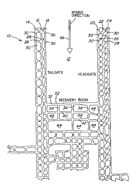
Figure 2 is a diagrammatic layout of a longwall mining
operation, illustrating the direction of advancement of the longwall
mining machine through a panel formed by tailgate and headgate entries
and the recovery room which is connected to a series of entries and
chutes.
Figure 3 is a schematic plan view of the first stage of the
roof support system for the recovery room behind the longwall panel
shown in Figure 2.
Figure 4 is a schematic view in side elevation of the first
stage development of the recovery room shown in Figure 2, illustrating
the roof support system.
Figure 5 is a view similar to Figure 4 of the first step
development of the recovery room, illustrating a roof truss system used
in the recovery room.
Figure 6 is an exploded isometric view, partially in section,
illustrating the components of the roof truss system shown in Figure 5.
Figure 7 is a schematic plan view of the recovery room after
the second stage of development with a completed roof control system.
Figure 8 is a schematic view in side elevation of the expanded
recovery room and roof support system therefor as shown in Figure 7.
Figure 9 is a schematic plan view of one of the intersections
formed by a recovery chute and an entryway at the rear of the recovery
room, illustrating the roof support system for the intersection.
Figure 10 is an enlarged schematic plan view of the longwall
mine layout behind the panel to be extracted, illustrating the recovery
room and the chutes extending rearwardly from the recovery room.
Figure 11 is a schematic plan view of the roof support system
for a headgate entry.
Figure 12 is a schematic plan view of the roof support system
for a tailgate entry.
Referring to the drawings and particularly to Figures 1 and 2
there is illustrated the layout of a longwall mining operation generally
designated by the numeral 10. The longwall mining operation is
conducted in a conventional manner by first forming a longwall panel 12
containing a seam of mine material to be extracted by a longwall mining
machine. A longwall mining machine suitable for use with the present
;;.. : , ~ : .
invention is disclosed in U.S. Patent No. 4,183,585 which is incorporat-
ed herein by reference. The panel 12 is first formed by conventional
methods such as a single entry mining machine in which a series of
substantially parallel entries 14, 16, 18, 20, 22, 24, are driven a
selected distance into the rock formation, for example 4,000 to 10,000
feet.
A plurality of bleeder entries, such as entries 26 and 28
shown in Figure 2, are driven at spaced apart intervals to provide
access to tailgate and headgate entries 18 and 20 from the adjacent main
entries 14, 16 and 22, 24. The bleeder entries 26 and 28 are separated
from one another by solid pillars 30. The tailgate and headgate. entries
18 and 20 extend the length of the panel 12. The tailgate and headgate
entries 18 and 20 begin at a set up room (not shown) where the longwall
mining machine is initially assembled to extract the panel 12. At a
preselected depth into the seam of mine material a recovery room 32 is
cut transversely across the panel 12 to connect the tailgate and
headgate entries 18 and 20. From the recovery room 32 are driven at
spaced apart intervals recovery chutes 34, 36 and 38. The chutes 34, 36
and 38, in turn, intersect spaced apart cross entries 40 and 42 which
extend transversely between the tailgate and headgate entries 18 and 20.
The formation of the chutes 34-38 and cross entries 40 and 42 outline a
plurality of pillars 44 that are left in place to provide support of the
overhead rock strata.
Before the extraction of the longwall panel 12 is commenced,
the longwall layout is developed as illustrated in Figure 2. The
development of the layout includes the installation of a roof support
system in the various entries and passageways in accordance with the
present invention as will be described hereinafter in greater detail.
Once the longwall layout is developed and the roof support
systems are installed, the extraction of the panel 12 is commenced in
the direction of advancement by the longwall mining machine as indicated
by the arrow 46 in Figure 2. The longwall mining operation is conducted
in a conventional manner in which a shearer-type cutting machine as
disclosed in U.S. Patent No. 4,183,585 traverses the panel 12 between
the tailgate entry 18 and the headgate entry 20. The material dislodged
from the face of the panel 12 is collected by a conveyor 48 that is
positioned beneath the rotary cutter drums or shearers (not shown) and
extends the width of the panel between the tailgate entry 18 and the
headgate entry 20. The rotary cutter drums and the conveyor are
protected by overhead shield supports 50, as schematically illustrated
in Figure 1.
The shield supports 50 are raised and lowered into and out of
contact with the mine roof by operation of hydraulic props. The shield -
supports are raised to engage the mine roof in side by side relation the
full width of the panel 12 to support the mine roof immediately above
the conveyor and shearers. As the panel is extracted hy the back and
forth traversing movement of the longwall shearers, the shield supports
50 are progressively forwardly advanced. The area of the mine roof
immediately behind the shield supports is permitted to collapse as
illustrated in Figure 1; however, the tailgate and headgate entries 18
. .:
13 ~
:IM;'.`.., . ,~ ,, .. ~ . .- . .
and 20 remain in place.
Figure 1 illustrates the prior art roof support system for the
recovery room 32 which is developed before the longwall panel 12 is
extracted. The longwall mining machine progressively advances the face
of the panel 12 from the set up room to the recovery room 32. The panel
12 is extracted completely through a termination line 52, shown in
Figure 1, where the panel breaks open into the recovery room 32. When
the longwall mining machine reaches the recovery room 32 it is disassem-
bled. The disassembled mining machine and the shield supports 50 are
10 moved from the recovery room 32 through the chutes 34-38 and the cross
entries 40 and 42 to the next location for set up.
As the longwall shearers approach the recovery room 32
substantial abutment pressures build up in the solid pillar positioned
immediately in front of the shield supports 50 up to the termination
line 52. In order to resist the abutment pressures and prevent failure
of the panel and the roof immediately in front of the shield supports,
particularly for a friable rock strata, the strata above the roof of the
recovery room 32 must be adequately reinforced so that the intense
abutment pressures can be dissipated through the reinforced strata above
the recovery room 32 to the adjacent solid pillars. If the roof support
for the recovery room 33 is inadequate to withstand and dissipate the
abutment pressures to surrounding stable rock strata, the roof between
the shield supports and the recovery room will fail.
In the past it has been the practice to reinforce the area
immediately in front of the shield supports 50 with the wire meshing and
14
~ ..- .. ..
.~
wire rope trusses. This requires a slow down in the material extraction
process and also subjects the personnel installing the additional roof
support to haæardous conditions when they must work ahead of the shield
supports. As illustrated in Figure 1, the conventional method of roof
support for the recovery room 32 includes cribs 54 and 56 positioned at
the termination line 52 of the longwall panel 12 and at the opposite
outby wall 57. Conventional roof bolts 58 are anchored in the mine roof
in a selected bolt pattern. In those instances where the roof in front
of the advancing shield supports 50 does not collapse the shearers
advanced through the termination line 52 into the recovery room 32.
The shearers advance into the recovery room 32 is intended to
cut out the row of cribs 54 without incident. However, in those
instances where the abutment pressures override into the roof in advance
of the shield supports 50 and the roof fails, the longwall mining
operation must be stopped to clear the roof fall and install wire
meshing and roof bolts where the roof has collapsed in advance of the
shield supports. Therefore, in accordance with the present invention
a roof control system is provided for the recovery room 32 and the other
adjacent entries and passageway formed in the longwall mining operation
that prevents roof falls in the area approaching the recovery room and
in adjacent entryways. The roof control system of the present invention
also serves to eliminate the use of cribbing in the recovery room and in
other areas such as the headgate and tailgate entries, chutes, and at
the intersection of entries.
., . :':
~,, "
In order to eliminate the risks of exposing personnel to
hazardous conditions ahead of the shield supports as the panel face
approaches the recovery room 32, it was determined that the roof of the
recovery room must be reinforced to withstand the abutment pressures.
As illustrated in Figures 3, 4, 7 and 8 the recovery room is expanded in
width in two stages from a conventional width of about 16 feet utilized
with the prior art system to about 36 feet with the present invention.
By expanding the width of the recovery room to approximately twice the
width utilized in the prior art system, a roof support system is
installed that reinforces the unstable rock strata over the recovery
room to withstand the abutment pressures. With the present invention,
the strata above the recovery room takes up or absorbs the abutment
pressures and transmits them to surrounding, more stable strata.
The expanded roof support system installed above the recovery
room, as illustrated in Figures 7 and 8, reinforces the rock strata so
that the intense abutment pressures that are encountered when the
advancing face of the panel 12 approaches the recovery room are
transmitted through the panel between the panel face and the recovery
room 32 to the reinforced strata above the recovery room and therefrom
to the solid pillars 44 remaining in place behind the recovery room 32
as illustrated in Figure 2. With this system the longwall mining
operation is not slowed down or interrupted as it approaches the panel
, termination line 52 for the installation of support immediately in front
of the shields to prevent failure of the pillar between the shield
supports 50 and the panel termination line 52.
16
~, ~
~ s ~
Prior to the extraction of the panel 12, the recovery room i5
constructed in accordance with one method in two stages. However, it
should be understood that the recovery room may also be constructed by
another method in one stage where a narrower recovery room is feasible
in view of more stable rock strata above the recovery room roof to
resist the abutment pressures of an advancing panel face. In both
methods, the resultant roof support system shown in Figure 7 is
utilized.
In the first stage of construction, as illustrated in Figures
3 and 4, a recovery room 60 is cut a preselected width the full
transverse length of the longwall panel 12, for example about 750 feet.
The roof control plan constructed during the first stage is shown in
Figures 3 and 4. In the second stage, as illustrated in Figures 7 and
8, the recovery room 60 is doubled in width from the initial stage and
additional roof support is installed in a preselected pattern in
accordance with the present invention. In this manner, the rock strata
over the recovery room is reinforced to resist abutment pressures as the
advancing panel face proceeds through the termination line 52 into the
recovery room without failure of the overhead strata. Expanding the
~20 recovery room width permits reinforcement of friable overhead strata so
`that the strata is more stable. If the expanse of the friable strata
over the recovery room is limited, the strata is adequately reinforced
; in one stage.
Referring to Figures 3 and 4, there is illustrated a recovery
room generally designated by the numeral 60 constructed of an initial
17
~,~ ~A
:
width and extending the entire transverse length of the panel 12 between
the tailgate entry 18 and the headgate entry 20 as shown in Figure 2.
In the first stage of construction the width of the recovery room 60, as
shown in Figure 3, extends between the termination line 52 at the inby
side to an opposite wall 62 at the outby side. In one example, this
width is approximately 18 feet.
Across the width of the recovery room is initially installed
a roof support system generally designated by the numeral 64. The roof
support system 64 includes primary support provided by a plurality of
mechanically anchored roof bolt assemblies generally designated by the
numeral 66. The roof bolt assemblies 66 are commercially available and
sold under the trademark "INSTAL" by Jennmar Corporation. A roof bolt
assembly suitable for use in the present invention is illustrated and
described in detail in U.S. Patent No. 5,244,314 which is incorporated
herein by reference. Each of the roof bolt assemblies 66 includes a
grade 75, 7/8 inch diameter roof bolt in a length of 6 feet. Secured to
the end of the bolt is a 7/8 inch diameter expansion shell assembly and
a resin compression ring. An anti-friction washer is positioned on the
outer end of the bolt emerging from the bore hole between a roof plate
and a forged head on the roof bolt. The end of the bolt in the bore
hole is anchored by both the mechanical expansion shell and a resin
bonding system that provides at least 2 feet of mixed and cured resin
along the upper end of the roof bolt. With this arrangement each roof
bolt assembly 66 is both mechanically and chemically anchored within the
bore hole to maintain the bolt in tension and thereby compress the
18
,~"~ , ",~
~Ç:`.` ~' :~: ~ '' : ' '
overlying layers of rock strata above the recovery room 60.
In order to supplement the primary roof control system
provided by the roof bolt assemblies 66 to withstand the frontal
abutment pressures exerted at the advancing panel face, supplemental
support is provided by a combination of roof truss assemblies generally
designated by the numeral 68 and an initial roof channel generally
designated by the numeral 70 in Figure 3. With this arrangement, the
roof of the recovery room is stiffened or reinforced to a degree that
the abutment pressures exerted by the advancing panel upon the pillar
adjacent the recovery room in advance of the shield supports 50 are
transmitted from the reinforced strata above the recovery room to the
solid rock strata over the pillars surrounding the recovery room.
As seen in Figure 3, a plurality of roof truss assemblies 68
span the width of the initial recovery room 60. The assemblies 68 are
spaced a preselected distance apart, for example, 4 feet apart. The
detailed structure of each roof truss assembly 68 is shown in Figures 5
and ~ and is described and illustrated in greater detail in allowed U.S.
Application Serial No. 962,255 filed October 16, 1992 and entitled
"Method And Apparatus For Supporting A Mine Roof" which is incorporated
herein by reference.
Fach roof truss assembly 68 uses a connected arrangement of
grade 75 one inch diameter rods 74 and 76. The rods 74 and 76 are
connècted by a coupler 78. The end portions of the coupled rods are
secured as close as possible to the rib forming the panel termination
line 52 at the inby side of the recovery room 60 and at the opposite rib
~ , } ,~
;~; ~! ' ' ; ' '" ' ' ' ' ~ ~ ~: :
.h', ~ ``: . ~ : ! . .: ,' ~
~;'''`'`'' " '' `~:., ` `
or wall 62 at the outby side of the recovery room by U-bolts 80 and
brackets 82 to roof bolt assemblies generally designated by the numeral
72. Each roof bolt assembly 72 corresponds in construction to the roof
bolt assemblies 66 described above and disclosed in U.S. Patent No.
5,244,314 for the primary support system of the recovery room roof.
The roof bolt assemblies 72 each include an elongated roof
bolt 84 having an enlarged head 86 with a washer 88 at one end and an
opposite threaded end portion 90. A mechanical expansion shell assembly
generally designated by the numeral 92 is threadedly engaged to the bolt
end portion 90. As well known, upon rotation of the roof bolt assembly
72, the shell assembly 92 expands into gripping engagement with the wall
of the bore hole to exert tension on the bolt 84 with the head ~6 of the
bolt bearing against the bracket 82 compressed against the mine roof 94.
To increase the anchorage of the roof bolt assembly 72 within the mine
roof bore hole, resin is used in combination with the roof bolt assembly
72 when it is installed. The use of resin adds strength to the
anchorage of the bolt 84 in the bore hole when torque i5 applied to the
bolt end portion 86.
The roof bolt assemblies 72 are inserted into bore holes
drilled into the mine roof at approximately a 45 angle so that the holes
extend into the rock strata supported by pillars. Onc~i the roof bolt
assemblies 72 are anchored in the solid rock strata, the U-bolts 80,
connected to separate rods 74 and 76, are positioned on an arm member 95
of the truss bracket 82 with the arcuate, closed end of the U-bolt 80
positioned oppositely of an abutment wall 96 of the bracket 82. The
~.;,.,.,. , ~:- ' .,: . , , .' . ,'' ', , '. - '
adjacent ends of the rods 74 and 76 are connected to the coupler 78.
The coupled rods 74 and 76 are then placed in tension by rotation of the
coupler 78 whereby the U-bolts 80 are maintained compressed against the
bracket abutment wall 96, as shown in Figure 5. Tensioning the anchored
truss assemblies 68 shifts the weight of the rock strata over the mined
out area of the initially formed portion of the recovery room 60
upwardly into the solid rock strata over the solid pillar remaining
forward of the advancing longwall shearers at the inby side of the
recovery room 60 and the solid material at the outby side of the
recovery room 60.
As the longwall dislodging operation progresses toward the
termination line 52 for the panel 12, the shield supports 50 also
advance toward the termination line 52. As the shield supports get
closer and closer to the termination line, the roof bolt assemblies 66
anchored in the strata above the termination line combine with the
shield supports 50 to maintain the pillar between the shield supports
and recovery room in place. By installing the angled roof bolts 72
close to the rib at the termination line 52, the roof truss assemblies
68 in the recovery room 60 interact with the shield supports 50 opposite
the panel face to reinforce the roof between the shield supports and the
termination line 52 to withstand the abutment pressure and prevent
fai~ure of the roof.
In addition to the combination of the roof bolt assemblies 66
and the roof truss assemblies 68, the roof control system of the present
invention also includes in the initially formed portion of the recovery
'_' ~
room 60 a roof channel generally designated by the numeral 70 in Figure
3. The roof channel 70 extends parallel to and is relatively closely
spaced from the outby wall 62. The channel 70, in one example, is
positioned approximately 4 feet from the outby wall 62 and has a
preselected length of about 20 feet which is less than the longitudinal
length of the recovery room 60 between the tailgate entry 18 and the
headgate entry 20. Therefore, a number of roof channels 70
are positioned in end to end relation the length of the outby wall 62.
A commercially available roof channel for use with the present
invention is made and sold by Jennmar Corporation and is described and
illustrated in detail in allowed U.S. Application Serial No. 061,841
filed May 14, 1993 and entitled "Bearing Plate", which is incorporated
herein by reference. The roof channel 70, as shown in Figure 3,
includes a high strength reinforced steel channel 98 having a plurality
of openings spaced a preselected distance apart along the center line of
the channel. A bearing plate 100 is positioned in overlying abutting
relation with each opening. A roof bolt assembly generally designated
by the numeral 102 in Figure 4 extends through each of the aligned
; openings of the bearing plate 100 and channel 98 into a bore hole
drilled vertically into the rock strata above the roof of the initial
recovery room 60.
Preferably, the roof bolt assemblies 102 include a grade 75
one inch diameter roof bolt in a length of 16 feet. Upon completion of
the installation of the roof bolt assemblies 66, the roof truss
~; assemblies 68 and the roof channel 70, the rock strata above the initial
' ~:
22
.
recovery room 60 is substantially reinforced to resist the abutment
pressures exerted by the advancing panel face. After the first stage
construction of the recovery room 60 is completed, the width of the
recovery room is expanded in a second stage as illustrated in Figures 7
and 8.
Referring to Figures 7 and 8, there is illustrated the second
stage in the development of the longwall recovery room 60 which is
widened to substantially twice width of the initially formed recovery
room 60 shown in Figures 3 and 4. In the example of the present
invention shown in Figure 3, the recovery room 60 is initially con-
structed to a width of approximately 18 feet between the termination
line 52 and the opposite outby wall 62. Then in the second stage of
development shown in Figure 7, the width of the recovery room is
expanded an additional 18 feet for a total width of approximately 36
feet extending from the termination line 52 to the final position of an
outby wall 104.
With this method, a recovery room generally designated by the
numeral 106 in Figures 7 and 8 is formed having a total width of
approximately 36 feet and a length corresponding to the transverse
length of the mine panel 12 between the tailgate entry 18 and the
headgate entry 20 as shown in Figure 2. However, the recovery room 106
can be narrower than 36 feet in width and constructed in one stage
rather than two stages if the condition of the overhead rock strata is
more stable and capable of withstanding the abutment pressures without
requiring the degree of roof support provided by expanding the width of
23
the recovery room in a two stage development.
As seen in Figures 7 and 8, the roof control system for the
completed recovery room 106 includes a plan having primary and supple-
mental roof support systems corresponding to those used for the roof
control system in the initial recovery room 60 shown in Figure 3. The
roof support system in the expanded section of the recovery room 106
includes roof bolt assemblies 108 corresponding to the roof bolt
assemblies 66, roof truss assemblies 110 corresponding to the roof truss
assemblies 68 and roof channels 112 and 114 each corresponding to the
roof channel 70 described above.
As seen in Figure 7, the support plan for the roof bolt assem-
blies 108, roof truss assemblies llO, and the roof channels 112 and 114
are positioned in an offset relationship with respect to the correspond-
ing support devices installed during the initial stage of development of
the recovery room 60 shown in Figure 3. The roof bolt assemblies 108
installed in the expanded section of the recovery room 106 are posi-
tioned in rows which are laterally offset a preselected distance from
the rows of roof bolt assemblies 66 installed in the first stage of the
development of the recovery room. In one example, the rows of roof bolt
assemblies 108 are offset a distance of about 2 feet from the rows of
roof bolt assemblies 66. Similarly, the roof truss assemblies 110 in
the expanded section of the recovery room 106 are offset a selected
distance, for example 2 feet, from the roof truss assemblies 68
installed in the initial recovery room 60.
24
The offset spacing of the truss assemblies 68 and 110 serves
to prevent interference in the installation and anchorage of the angled
roof bolts for the truss assemblies at the adjacent end portions at the
center of the recovery room 106. The offset relationship of the angled
roof bolt assemblies for the trusses also provides uniform distribution
of the reinforcement of the strata above the recovery room roof. This
arrangement avoids excessive stress concentrations at the points where
the angled roof bolts are installed in the mine roof. Also, by spacing
the various support systems in a preselected pattern across the expanse
of the roof of the recovery room 106, the systems interact to provide
complete support of an expansive
area not otherwise adequately supported by conventional roof support
methods.
At the center of the expanded recovery room 104, the addition-
al roof channels 112 and 114 are installed in spaced parallel relation
with the initial roof channels 70. Preferably, the roof channels 70 and
112 are spaced about 4 feet apart on centers as are roof channels 114
and 112. The roof channels 112 and 114 correspond in structure to the
roof channel 70. The steel channel members 70, 112 and 114 each include
a plurality of openings spaced a distance apart along the length of the
channel member to receive the roof bolt assemblies 102. This arrange-
ment provides uniform distribution of the reinforcement by the roof bolt
assemblies 102 located at the center span of the recovery room 106.
The respective channel members 70, 112, and 114 are positioned
so that the holes through the channel members for receiving the roof
~ ~,
~. . . .
~`' . ' .
bolt assemblies 102 are not aligned oppositely of one another. The
channel members are positioned so that the holes are offset or staggered
as shown in Figure 7. In Figure 7, the positions of the bearing plates
100 indicate the location of the holes in the channel members where the
roof bolt assemblies 102 are installed.
The offset spacing of the channel member holes is coordinated
with the offset spacing of the roof truss assemblies 68 and 110 at the
mid span area of the recovery room roof. At the mid span area the roof
trusses 68 and 100 and roof channels 70, 112, and 114 are positioned in
overlying relationship. The staggering of the roof channels permits the
angled roof bolts 72 for the trusses 68 to be installed without
interference by the roof channels. For the center roof channel 112, the
holes for the 16 foot bolts are positioned between adjacent truss
members 68 and 110, thereby distributing the forces applied by these
roof support systems to the overhead rock strata.
As seen in Figure 7, the full width of the recovery room 106
between the termination line 52 and the outby wall 104 is not traversed
~; by a single roof truss. A single roof truss is not feasible for a
recovery room having the expanded width of recovery room 106 of the
present invention. However, the effect of a single roof truss spanning
the full width of the recovery room is accomplished by the offset
arrangement of the roof truss assemblies 68 and 110 between the inby
-i wall or termination line 52 and the outby wall 104.
As shown in Figure 7, the trusses 68, 110 meet in offset
relation at the mid span area in overlying relation with the roof
26 ~
'` `
`- `, "
channels 70, 112 and 114. The staggered arrangement of roof truss
assemblies 68, 110 and roof channels 70, 112, 114 interact with the
primary roof support achieved by the offset rows of roof bolt assemblies
66, 108 to provide a concentrated support system. This support system
uniformally distributes compressive forces throughout the rock strata
above the roof of the recovery room 106 and into the adjacent areas of
the rock strata supported by the solid pillars.
As described above, the recovery room 106 is constructed in
two stages to form a recovery room approximately twice the width of
conventionally known recovery rooms in a longwall mining operation.
Expanding the recovery room width permits installation of a roof support
system that replaces friable rock strata that otherwise presents
hazardous conditions to operating personnel and equipment. The roof
control system of the present invention includes a variety of roof
support devices designed to interact with one another to enhance the
roof support and eliminate the risks associated with friable rock
strata.
The overhead support achieved in a 36 foot wide recovery room
by the roof control system of the present invention provides greater
support to re~ist the abutment pressures generated by the advancing mine
face than for a 18 foot recovery room surrounded by friable rock strata.
Removing the friable rock strata by expanding the width of the recovery
room and reinforcing the roof of the recovery room by the control system
of the present invention solves the problem of failure of the roof
immediately forward of the shield supports 50 near the panel termination
27
~. ~
line 52.
With an expanded and reinforced recovery room 106, the
longwall shearers maintain a normal rate of advancement because the roof
and mine face remain intact throughout the recovery aperations. The
longwall shearers break through the termination line 52 and advance into
the recovery room 106 without failure of the rock strata above the roof
of the recovery room. Furthermore, the recovery room remains intact to
permit disassembly of the face equipment and its movement through the
recovery chutes 34, 36 and 38 extending off the recovery room as shown
in Figure 2.
Referring to Figure 10, there is illustrated in detail the
layout of the longwall mine behind the recovery room 106 expanded and
supported in accordance with the present invention. Extending through
the outby wall 104 of the recovery room 106 are cut reaovery chutes 34,
36 and 38. The chutes 34-38 intersect transversely with cross entries
40 and 42 which extend parallel to the recovery room 106. The formation
of the intersecting chutes 34-38 and cross entries 40 and 42 leaves a
number of pillars of rock material in place to support the overhead
strata. The passageways provided by the chutes and cross entries are
used to transport the disassembled longwall mining machinery to the next
set up room for dislodging another panel. The intersections of the
chutes and cross entries are supported by a system that includes the
; roof support devices used in the recovery room as discussed above. ~"~
Figure 9 illustrates a roof support system used at the
intersection of recovery chute 36 and cross entry 40. This system is `
28 ~`
used at the intersection of each recovery chute and cross entry. Each
of the recovery chutes 34-38 includes a roof support plan formed by
truss assemblies 116 that extend the full width of each chute and are
installed 4 feet apart. The truss assemblies 116 are also supplemented
by roof bolt assemblies 118. The truss assemblies 116 correspond to the
truss assemblies illustrated in Figures 5 and 6 and described above in
which coupled rods bars 74 and 76 are connected at their end portions to
roof bolt assemblies 72 that are angled to extend into the solid
material of the pillars forming the passageways. The cross entries are
also provided with overhead roof support the full length of the entries.
Truss assemblies 120 are installed the length of the cross
entry 40 and extend through the intersection with the recovery chute 36
as well as the recovery chutes 34 and 38 shown in Figure 10. Roof bolt
assemblies 122 are also positioned in underlying relationship with the
truss assemblies 120. Supplementing the truss assemblies 120 in the
cross entry 40 are rows of roof bolt assemblies 124. The roof bolt
assemblies 124 also correspond to the roof bolt assemblies used in the
recovery room and the other passageways of the mine. The rows of the
roof bolt assemblies 124 are positioned between adjacent roof truss
assemblies 120 in the cross entry 40. This pattern of ~oof support is
repeated the entire length of the cross entry 40.
, At the intersection of chute 36 and cross entry 40 illustrated
in Figure 9, the roof bolt assemblies 124 preferably include 16 foot
length bolts as above-described for the longwall recovery room.
29
~,., : ;~,, :
,~
b; '
~1 ^ ~ ` ,,
Accordingly, with the roof control pattern shown in Figure 9, each four
way intersection includes 26 roof bolts each having a 16 foot length
extending vertically into the overhead rock strata. With this arrange-
ment of truss assemblies and roof bolt assemblies at each intersection,
the risks of a roof fall occurring due to a pressure shift induced by
the trusses installed in the cross entryways is substantially reduced.
As illustrated in Figure 2, the tailgate entry 18 and the
headgate entry 20 extend the length of the longwall panel 12 to be
dislodged from the set up room (not shown) to the recovery room 32. As
the tailgate and headgate entries are developed the exposed overhead
roof of the respective entries is supported with a roof control system
in accordance with the present invention. The strata above the tailgate
and headgate entries is supported to resist the lateral pressures -;
exerted on the strata as the panel 12 is advanced and the overhead
strata behind the shield supports 50 is allowed to cave-in. Figures 11 `;~
and 12 illustrate the roof control systems installed in the headgate and ~
tailgate entries respectively. -`
The support system for the headgate entry 20 shown in Figure
11 is similar to that utilized in the recovery room 106 and recovery ~-
chute 36 illustrated in Figures 7 and 9. In Figure 11, a portion of the
headgate entry 20 is shown at an intersection with a bleeder entry 26. ~ ~
As with a recovery room or a recovery chute, the overhead strata above ~i
the headgate entry is supported by a primary system of roof bolt ~`
assemblies 126 installed in accordance with a roof bolt plan where rows
of the assemblies 126 are positioned a preselected distance apart. The -~`
:` . '
-~
assemblies 126 are coordinated with the spacing of roof bolt assemblies
128 installed in the bleeder entry 26.
Supplementing the roof bolt assemblies 126 are roof truss
assemblies 130 corresponding in construction to the truss assemblies
installed in the recovery room 106 as shown in Figure 7 and in the
recovery chute 36 as shown in Figure 9. The roof truss assemblies 130
traverse the width of the headgate 20, which is one example is about
eighteen feet wide. The assemblies 130 are spaced a preselected
distance apart and are installed the full length of the headgate entry
20. The ends of the truss assemblies 130 are anchored by roof bolts
132, as above described, to the solid rock strata above sidewalls 134
and 136. The sidewall 134 defines the longitudinal sidewalL of the
panel 12 which is progressively extracted. The sidewall 136, however,
remains in place.
As the panel 12 is progressively removed, the sidewall 134 is
also removed. However, the roof bolts 132 extend a sufficient depth
into the rock strata so that they remain anchored as the roof behind the
shield supports 50 is allowed to collapse. In this manner, the roof
above the headgate entry 20 remains in place to permit continued use of
the headgate entry 20 as the panel 12 is extracted. The combination of
the rows of bolt assemblies 126 positioned in alignment with the roof
truss assemblies 130 reinforces not only the strata above the roof of
the headgate entry, but the strata over the adjacent sidewalls 134 and
136, as well. Consequently, as the panel 12 is extracted, the roof
above the headgate entry 20 remains safely in place.
~ ~ ,.......... '
~", '" '...... ~ '
The roof support plan for the headgate entry 20 iB also
repeated in the bleeder entry 26 so that the compressive forces applied
to the overhead strata by the roof bolt assemblies 126 and the roof
truss assemblies 130 is equally distributed throughout the strata. This
prevents a concentration of compressive forces applied to the overhead
strata which could contribute to a roof fall.
The above described roof support plan for the headgate entry
20 can also be used in the tailgate entry 18. In addition, an alternate
plan can be used in either the headgate or tailgate entries as illus~
trated for the tailgate entry 18 shown in Figure 12 in which like
numerals are used to designate like elements described above and
illustrated in Figure 11. In addition to the roof truss assemblies 130,
roof channels 138 are installed in spaced parallel relation to one
another. The roof channels 138 are spaced a preselected distance apart
and equally spaced from adjacent roof truss assemblies.
The roof channels 138 are compressed against the roof above
the tailgate entry 18 by a plurality of roof bolt assemblies 140
anchored a preselected depth into the overhead strata. Preferably, the
roof bolt assemblies 140 utilize mechanically and resin anchored roof
bolts in a length of about eight feet. Once anchored in the roof
strata, the bolts are tensioned so that the bearing plates retained on
the ends of the bolts are compressed against the channel members 138.
Again, the roof control system used in the tailgate entry 18
is repeated in the bleeder entry 26 to provide complementary roof
support systems that interact with one another to securely support the
32
F2~
\
overhead strata. Depending on the condition of the overhead strata, it
may be necessary to use additional support systems described above~ In
addition, there may be occasions when supplemental support in the form
of conventional cribbing 142 is utilized in the bleeder entry 26 as
shown in Figure 12. Thus, in accordance with the present invention,
roof control systems are provided which serve to retain the rock strata
above the tailgate and headgate entries 18 and 20 securely in place as
the longwall panel 12 is progressively extracted.
With the present invention in a longwall mining operation, the
panel face is continuously dislodged by the transversing movement of the
shearers from the set up room to the recovery room without encountering
delays due to a roof fall immediately forward of the advancing shield
supports. The advancing face and roof forward of the shield supports
remains in tact throughout the mine material dislodging operation. The
longwall shearers cut into the recovery room without encountering roof
control problems. The recovery room and recovery chutes remain intact,
enabling quick teardown of the mining equipment in the recovery room and
its movement through the recovery chutes to the next panel for set up.
The teardown operation in the reinforced recovery room is
performed substantially free of the risk of a roof fall. The personnel
are securely protected by a comprehensive roof support system in
accordance with the present invention. The use of cribbing and wire
screening used in conventional recovery operations can be eliminated
with the roof control system of the present invention. This permits the
longwall mining operation to be completed in a shorter period of time
33
.~
" ~
~;,`3',~`,-:. '- . . ` '
: :
which substantially improves the cost effectiveness of the mining
operation.
According to the provisions of the patent statutes, we have
explained the principle, preferred construction, and mode of operation
of our invention and have illustrated and described what we now consider
to represent its best embodiments. However, it should be understood
that within the scope of the appended claims, the invention may be
practiced otherwise than as specifically illustrated and described.
34