Note: Descriptions are shown in the official language in which they were submitted.
21~4~9~
PATENT
METHOD OF JOINING AN ELASTIC BAND TO A CONTINUOUSLY
MOVING PARTIALLY ELASTIC SUBSTRATE
Background of the Invention
The present invention relates to methods of joining a length of
material to a continuously moving substrate, and more particularly to
methods of joining an elastic material to a continuously moving,
partially elastic substrate.
There are, today, an increasing number of products incorporating some
type of elastic material to provide stretch to the products.
Examples of these products incorporating elastic material include
general wearing apparel, athletic apparel, and specialized apparel,
such as surgical gowns, hospital gowns, and other medically-related
apparel.
Other examples of different types of product include vehicle
protective covers, camping-related materials such as tents for
example, or the like.
Still other examples include disposable absorbent articles, such as
baby diapers, children's training pants, adult incontinence products,
feminine care products, or the like.
-1-
~134~9~
One of the intended purposes of incorporating elastic materials into
these products is to keep the products secure or snug in their proper
positions. For example, certain designs of general wearing apparel
may require a tight fit so as to have a uniquely fashionable look.
Athletic apparel needs to be maintained in place during aggressive
physical activity required in some sports. Surgical and hospital
apparel needs to fit properly for sanitary and health purposes.
Similarly, vehicle protective covers and camping-related materials
desirably should withstand the effects of high or gusty winds and
other severe weather conditions. A secure fit, whether over a
vehicle or a tent frame, for example, can help weather these types of
outdoor conditions.
In the area of disposable absorbent articles, a proper fit, both
before and after an accident or insult, is important in preventing
body waste material from leaking out of the product onto the wearer.
One problem associated with incorporating an elastic material into a
product is the elastic material's potentially premature contracting
during the manufacturing process. Any premature gathering of the
product can cause subsequent processing steps to be off-line or
unregistered, thereby resulting in material waste and increased costs
in manufacture. One specific example of this is a training pant
intended to be worn during the potty-training stage of young
children. One style of training pant has elastic side panels that
fit against the hips of the child, and discrete front and back
elastic waist strips adjacent the waist opening. The waist strips
_2_
~134~9~
are applied during the manufacturing process, and generally at a
different point or time in the process from the elastic side panels.
The individual training pants are folded and bonded along portions of
side edges to form a waist opening and a pair of leg openings. If,
for example, the elastic waist strips prematurely gather, the
subsequent folding and bonding steps will not be properly performed,
thereby resulting in irregular products that must be culled and
disposed of.
Another problem associated with incorporating an elastic material
into a product is the difficulty of properly maintaining a desired
elasticity in the product during both the joining of the elastic
material and subsequent handling steps. If the desired elasticity
cannot be maintained, the product may not fit properly, and
ultimately result in unsatisfactory performance.
A further problem exists when incorporating an elastic material into
a partially elastic product, and particularly during the
manufacturing process when the extensible direction of the elastic
material is different from the direction of run of a continuous,
partially elastic substrate, from which multiple individual products
will be made. This problem is complicated when the partially elastic
substrate is extensible in the same direction as the elastic material
and it is desired that the joining of the elastic material should not
substantially inhibit the desired elasticity of the partially elastic
substrate. For example, the continuously running length of partially
elastic substrate, from which some type of apparel is to be made, can
have elastic portions that extend in a direction transverse to the
-3-
~1~4~9
direction the substrate is being run. A problem arises here when an
elastic material, such as an elastic band for example, is to be
joined to the partially elastic substrate such that the direction of
extension of the elastic band also is transverse to the direction the
partially elastic substrate is being run.
Yet another problem is the accurate joining of an elastic material in
today's high speed manufacturing environment. Some products are
manufactured at speeds of about 200-800 products per minute. Since
the materials that form the product are provided at relatively high
speeds, problems in material handling must be avoided if the
manufacturing process is to be fast, continuous, and economical.
Otherwise, there will be unacceptable and costly downtime in the
manufacturing process to correct these problems.
In view of the above, there is a need today for a process for joining
an elastic material to a continuously moving, partially elastic
substrate.
Summary of the Invention
In one form of the present invention there is provided a method of
joining a plurality of elastic bands to a continuously moving,
partially elastic substrate comprising the steps of (1) continuously
moving in a first direction a substrate including a plurality of non-
elastic segments and a plurality of elastic segments that are
extensible in a direction different from the first direction, (2)
delivering a plurality of elastic bands, (3) sequentially orienting
each elastic band, relative to the continuously moving substrate, so
-4-
_ ~134~9
that each elastic band is extensible in a direction different from
the first direction, (4) positioning each elastic band over at least
one non-elastic segment and at least one elastic segment of the
continuously moving substrate, and (5) joining each elastic band to
the continuously moving substrate.
In another form of the present invention there is provided a method
of joining a plurality of elastic bands to a continuously moving,
partially elastic substrate comprising the steps of (1) continuously
moving in a first direction a substrate including a plurality of non-
elastic segments and a plurality of elastic segments that are
extensible in a direction different from the first direction, (2)
providing a supply of an elastic band, (3) temporarily inhibiting
portions of the elastic band, (4) cutting the elastic band into
individual elastic bands so that each individual elastic band
includes at least one temporarily inhibited portion and at least one
elastic portion, (5) sequentially orienting each individual elastic
band so that it is extensible in substantially the same direction as
the elastic segments of the continuously moving substrate, (6)
positioning each individual elastic band over the continuously moving
substrate so that the elastic portion of the band is over one of the
elastic segments of the substrate, and the temporarily inhibited
portion of the band is over one of the non-elastic segments of the
substrate, and (7) joining each individual elastic band to the
continuously moving substrate.
In still another form of the present invention there is provided a
method of joining a plurality of elastic bands to a continuously
-5-
- ~134~9
moving, partially elastic composite structure comprising the steps of
(1) continuously moving in a first direction a composite structure
including a continuous topsheet, a continuous backsheet, a plurality
of spaced apart absorbent structures between the continuous topsheet
and continuous backsheet, and a plurality of spaced apart elastic
side members on opposite sides of the continuous backsheet and being
extensible in a direction different from the first direction, (2)
providing a supply of an elastic band, (3) temporarily inhibiting
portions of the elastic band, (4) cutting the elastic band into
individual elastic bands so that each individual elastic band
includes a pair of elastic portions and a temporarily inhibited
portion therebetween, (5) sequentially orienting each individual
elastic band so that it is extensible in substantially the same
direction as the elastic side members, (6) positioning each
individual elastic band over the continuously moving composite
structure so that the temporarily inhibited portion of the band is
over the backsheet, and a pair of elastic portions are over a
respective pair of opposite spaced apart elastic side members, and
(7) joining each individual elastic band to the continuously moving
composite structure.
In still yet another form of the present invention there is provided
a method of joining a plurality of elastic bands to a continuously
moving, partially elastic substrate comprising the steps of (1)
continuously moving in a first direction a substrate including a
plurality of non-elastic segments and a plurality of elastic segments
that are extensible in a direction different from the first
direction, (2) providing a supply of a heat-elasticizable band, (3)
-6-
CA 02134595 2004-04-23
elastically activating selected portions of the heat-elasticizable
band, (4) cutting the heat-elasticizable band into individual heat-
elasticizable bands so that each individual heat-elasticizable band
includes at least one elastically activated portion and at least one
non-activated heat-elasticizable portion, (5) sequentially orienting
each individual heat-elasticizable band so that it is extensible in
substantially the same direction as the elastic segments of the
continuously moving substrate, (6) positioning each individual heat-
elasticizable band over the continuously moving substrate so that the
elastically activated portion is over one of the elastic segments of
the substrate, and the non-activated heat-elasticizable portion is
over one of the non-elastic segments of the substrate, and (7)
joining each individual heat-elasticizable band to the continuously
moving substrate.
zn a further aspect of these embodiments of the invention, the
elasticity of the temporarily inhibited portion is less than the
elasticity of the elastic segment of the substrate.
Brief Description of the Orawing~
The above-mentioned and other features of the present invention and
the manner of attaining them will become more apparent, and the
invention itself will be better understood by reference to the
following description of the invention, taken in conjunction with the
accompanying drawings, wherein:
Fig. 1 illustrates a front perspective view of one type of a
disposable, elastic, absorbent garment made in accordance with the
principles of the present invention;
Fig. 2 illustrates a partially exploded view of Fig. 1 with a
continuous, elastic waistband separated from the garment;
~134~9
Fig. 3 illustrates a cross-sectional view of Fig. 1 taken along
line 3-3 and viewed in the direction of the arrows;
Fig. 4 illustrates an exploded, perspective view of the garment in
Fig. 1 in a partially disassembled, extended flat state;
Fig. 5 illustrates a top plan view of the garment in Fig. 1 in a
partially finished, extended flat state;
Fig. 6 illustrates schematically one method of the present invention;
and
Fig. 7 illustrates schematically a modification of the method in Fig.
6.
Definitions
Each of the following terms used herein include the following
meaning:
"Composite elastic material" or "composite elastic web" means a
multi-layered material having at least one elastic layer joined to at
least one gatherable layer at least at two locations wherein the
gatherable layer is gathered between the locations where it is joined
to the elastic layer. A composite elastic material may be stretched
to the extent that the non-elastic material gathered between the bond
locations allows the elastic material to extend. This type of
composite elastic material is disclosed, for example, by under
_g_
CA 02134595 2002-07-15
Wielen et al., U.S.~Patent No. 4,720,415 issued January 19, 1988.
"Continuous" means that the described structure is a closed-loop
structure. The continuous structure may be unitary, i.e., a one-
piece structure, or may be made up of individual elements suitably
joined together to form a closed-loop.
"Disposable" means that the described garment is designed to be used
until soiled, either by urination, defecation, or otherwise, and then
discarded, rather than being washed and used again.
"Elastic", "elasticity", "elasticized", and the like, refers to a
material or composite material that tends to recover its original
size and shape after removal of the force causing the deformation,
and is expressed as a percent.
"Elongation" means the ratio of the extension of a material to the
length of the material prior to the extension (expressed in percent),
as represented by the following:
M ended Length - Original Lennth
Original Length x 100.
"Extension", "extend", "extended", or variations thereof, refers to
the change in length of a material due to stretching (expressed in
units of length).
_g_
~13~~~
"Extensible" means that the described material can be increased in
length.
"Finished garment" means that the garment has been suitably
manufactured for its intended use.
"Join", "joining", "joined", or variations thereof, when used in
describing the relationship between two or more elements, means that
the elements can be connected together in any suitable manner, such
as by heat sealing, ultrasonic bonding, thermal bonding, by
adhesives, stitching, or the like. Further, the elements can be
joined directly together, or may have one or more elements interposed
between them, all of which are connected together.
"Operatively elastically joined" describes the joining of an elastic
member to a non-elastic member such that the two joined members
exhibit elasticity.
"Pant body" refers to a garment that has a waist opening and a pair
of leg openings, similar to shorts, swim wear, or the like. The
described garment may or may not have a manually tearable side seam.
"Recover", "recovering", or variations thereof, refers to a
contraction of an extended material upon termination or removal of a
biasing force, or upon suitably treating the material after it has
been temporarily inhibited.
- 10 -
~1~4~~5
"Substrate" means a layer which may be, for example, a film, woven
web, or nonwoven web; or a composite structure comprising, for
example, a topsheet, a backsheet, and an absorbent medium
therebetween.
"Temporarily inhibit" means to delay the total recovery of an
extended elastic substrate or composite elastic material. The delay
may be imparted by compressing the extended elastic substrate, or by
compressing the composite elastic material so that the elastic and
gatherable layers are temporarily joined. Partial recovery of a
temporarily inhibited elastic substrate or composite elastic material
may occur immediately after the force is removed, but total recovery
of such a temporarily inhibited elastic substrate or composite
elastic material will require more time than the total recovery of
the same material which has not been temporarily inhibited. For
example, total recovery of an extended elastic substrate or composite
elastic material that has not been temporarily inhibited may be
instantaneous, whereas the total recovery of a temporarily inhibited
elastic substrate or composite elastic material may take, for
example, from about 5 to about 60 seconds.
"Total recovery" or variations thereof, refers to a material
recovering to generally within about 20 percent of its relaxed, pre-
extended dimensions.
Detailed Description
The present invention can be utilized to manufacture any type of
product that is partially elastic, and to which is to be joined an
- 11 -
~134~~
elastic material or band. The present invention is especially useful
when the individual products are being manufactured from a
continuously moving partially elastic substrate having elastic
portions extensible in a direction different from the direction of
travel of the continuously moving substrate, and to which is to be
joined an elastic material or band that stretches in the same
direction as the elastic portions of the continuously moving
substrate. Some of the products contemplated to be manufactured in
accordance with the principles of the present invention include
apparel, vehicle protective covers, camping-related materials,
disposable absorbent articles, or the like. The description of a
method of the present invention will be made with reference to one
specific product, but it should be understood that the present
invention is adaptable to manufacture other and differing types of
products as described above.
Referring primarily to Fig. 1, there is illustrated a partially
elastic composite structure in the form of a disposable absorbent
garment 10. The phrase "partially elastic composite structure"
includes a garment or product comprising two or more structural
elements, such as two or more layers of material, and having portions
thereof that are elastic. Disposable absorbent garment 10 includes a
pant body 12 comprising a front section 14, a back section 16, a
crotch section 18, elastic side sections 20, seams 22, a continuous
waist opening 24, and a pair of continuous leg openings 26. Each
elastic side section 20 includes a front elastic side member 68 (Fig.
5) and a back elastic side member 70, which are joined together at a
respective seam 22. Garment 10 further includes a continuous
- 12 -
213~~9~
waistborder 30 (Figs. 1-2), continuous leg borders 38, and a
continuous waistband 32. Continuous waistband 32 comprises a front
waistband member 64 (Fig. 5) and a back waistband member 66.
Continuous waistborder 30 comprises a front waistborder section 42
(Figs. 4, 5) having a front edge 44 and a back waistborder section 46
having a back edge 48. An absorbent structure 28 is suitably
incorporated into garment 10 at least at crotch section 18 thereof.
Pant body 12 includes a topsheet 34 (Fig. 4) and a backsheet 36,
which are desirably coincident with one another, although not a
requirement of the present invention. Backsheet 36 (Fig. 5) includes
a pair of front outer edges 50, front inner edges 52, innermost edges
54, back sloping edges 56, and back outer edges 58.
Front waistband member 64 (Figs. 4, 5) is suitably joined to front
waistborder section 42, and back waistband member 66 is suitably
joined to back waistborder section 46. Front and back waistborder
sections 42, 46 desirably have respective lengths substantially
corresponding to the respective lengths of front and back waistband
members 64, 66, and widths substantially corresponding to the
respective widths of front and back waistband members 64, 66; length
being measured along a line generally parallel to transverse
centerline 60 (Fig. 5) and width being measured along a line
generally parallel to longitudinal centerline 62. A desired width
range of waistband members 64, 66 is between about 1 centimeter to
about 8 centimeters, and a more desired range is between about 2
centimeters to about 4 centimeters. In the case where, for example,
one or both of the waistband members 64, 66 have some other geometric
- 13 -
~134a9~
shape, i.e., not an elongate rectangular shape as illustrated in
Figs. 4 and 5, each waistborder section 42, 46 desirably would have
substantially the same geometric shape as its respective waistband
member 64, 66. Both front and back waistband members 64, 66 are
elastically extensible at least in a direction generally parallel to
transverse centerline 60.
With reference primarily to Figs. 1 and 5, when garment 10 is folded
along a transverse fold-line, which is generally parallel to
transverse centerline 60, and pairs of aligned front and back outer
edges 50, 58 are joined together to form seams 22, the following
construction is accomplished: (i) front waistborder section 42 and
back waistborder section 46 form or define continuous waistborder 30;
(ii) front waistband member 64 and back waistband member 66 form or
define continuous waistband 32; (iii) a front inner edge 52, an
innermost edge 54, and a back sloping edge 56 form or define a
respective leg opening 26; (iv) and a front elasticized side member
68 and a back elasticized side member 70 form or define a respective
elasticized side section 20.
Garment 10 also comprises a pair of leg elastic members 72 (Fig. 5)
that are suitably joined, for example, between topsheet 34 and
backsheet 36 (Fig. 1).
Absorbent structure 28 (Figs. 4, 5) comprises front absorbent edge
74, back absorbent edge 76, and absorbent side edges 78. As
illustrated in Fig. 5, front absorbent edge 74 and back absorbent
edge 76 are respectively inboard of front waistband member 64 and
- 14 -
back waistband member 66. Similarly, absorbent side edges 78 are
inboard of respective leg elastic members 72. By "inboard" is meant
that absorbent front edge 74, for example, is closer to transverse
centerline 60 than front waistband member 64, and absorbent side
edges 78 are closer to longitudinal centerline 62 than leg elastic
members 72.
When garment 10 is properly fitted on the wearer, topsheet 34 faces
toward the body of the wearer, and may or may not be the layer that
directly contacts the skin. Topsheet 34 can be a liquid permeable,
elastic or non-elastic, substantially hydrophobic material, such as a
spunbonded web of synthetic polymer filaments. Topsheet 34 can also
be a meltblown web or a bonded carded web of synthetic polymer
filaments. Suitable synthetic polymers include, for example,
polyethylene, polypropylene, and polyesters. Topsheet 34 has a pore
size that readily allows the passage therethrough of liquids, such as
urine and other body exudates. If desired, topsheet 34 can be
treated with surfactants to selectively adjust its degree of
wettability, and can also be selectively embossed or perforated with
discrete slits or holes extending therethrough. Suitable topsheet
materials can have a basis weight between about 10 grams per square
meter (gsm) to about 26 gsm, and a thickness between about 0.013
centimeters to about 0.064 centimeters. The thickness of the
topsheet material can be determined by employing an Ames Bulk Test
(ASTM D-1777) performed at a restraining pressure of 0.2 psi (1.38
kPa).
- 15 -
~1~~595
Backsheet 36, which may or may not-be the outermost layer of garment
10, can be liquid permeable or liquid impermeable, and may or may not
have breathability, i.e., be vapor permeable. A suitable liquid
permeable backsheet 36 is a nonwoven bicomponent web having a basis
weight between about 15 gsm to about 50 gsm. The nonwoven
bicomponent web may be a spunbond bicomponent web, or a bonded carded
bicomponent web. Suitable bicomponent fibers are a wettable,
polyethylene/polypropylene bicomponent fiber available from CHISSO
Corporation, Osaka, Japan. In this particular bicomponent fiber, the
polypropylene forms the core and the polyethylene forms the sheath of
the fiber. Other fiber orientations are possible, such as multi-
lobe, side-by-side, or end-to-end. Another suitable liquid permeable
material is a liquid permeable spunbond polypropylene nonwoven web
having a basis weight between about 15 gsm to about 50 gsm.
A suitable liquid impermeable backsheet 36 is a 0.0015 centimeter
polyethylene film from Edison Plastics Company, South Plainfield,
New Jersey. Backsheet 36 can also be a two-ply laminate, in which
the innermost layer can be the above-described liquid impermeable
film or any other suitable liquid impermeable layer, and the
outermost layer can be the above-described liquid permeable spunbond
polypropylene nonwoven web or any other suitable liquid permeable
layer. Backsheet 36 desirably has a thickness within the range of
about 0.0013 to about 0.0051 centimeters.
Absorbent structure 28 can comprise any suitable absorbent material,
natural or synthetic, or a combination thereof, along with
superabsorbent material. The absorbent material of which absorbent
- 16 -
CA 02134595 2002-07-15
structure 28 is made may also be encased in a tissue wrap (not shown)
in order to maintain the integrity of the absorbent material
comprising absorbent structure 28. Suitable superabsorbent materials
are available from various vendors, such as Dow Chemical Company,
Hoechst-Celanese Corporation, and Allied Colloids, Inc. A suitable
natural absorbent material is a wood pulp fluff identified by the
trade-mark CR1654 from Kimberly-Glark Corporation, Neenah,
Wisconsin. One specific absorbent structure 28 that can be suitably
used in garment 10 is described in U.S. Patent 5.509.915.
inventors Hanson et al., which is
assigned to the assignee of this applicati~an.
The construction of garment 10 can be accomplished in any suitable
manner. For example, the structural elements can be joined together
in any manner, such as by heat sealing or ultrasonic bonding, or by
adhering the elements together with a suitable adhesive. Suitable
adhesives can be obtained from Findley Adhesives, Inc., Wauwatosa,
Wisconsin, and can be applied in any manner, such as by spraying,
slot-coat extrusion, printing, or the like. The applied adhesive can
be in any desired configuration, such as continuous or discontinuous
beads, continuous or discontinuous swirls, meltblown patterns, spray
patterns, or the like.
Referring to Figs. 1-5, front elasticized side members 68 (Fig. 5)
can have the same or different geometry from back elasticized side
members 70. Each front elastic side member 68 and each back elastic
side member 70 comprises an elastic layer 80 (Fig. 3) sandwiched
- 17 -
CA 02134595 2002-07-15
between topsheet 34 and backsheet 36. Elastic layer 80 can be any
suitable elastic material, such as any of the materials in the
KRATON~ G and KRATON~ D series of The Shell Chemical Company.
Elastic layer 80 can be a film, nonwoven web, or ribbons or threads
of synthetic or natural rubber arranged, for example, in a spaced,
parallel manner. Similar to front and back waistband members 64, 66,
front and back elasticized side members 68, 70 are elastically
extensible at least in a direction generally parallel to transverse
centerline 60.
Each elastic layer 80 is operatively elastically joined to a portion
of either topsheet 34 or backsheet 36, preferably to portions of both
topsheet 34 and backsheet 36, in order to provide elasticity to those
portions. One example of this is disclosed in published EP
Application 743.02.
Another example of providing elastic side sections 20 is
described in U.S. Patent No. 4,940,464, issued July 10, 1990, to
inventor Van Gompel et al.
Still other examples of elastic materials and composites are
described in U.S. Patent No. 4,720,415, issued January 19, 1988, to
Vander Wielen et al.; U.S. Patent No. 4,657,802, issued April 14,
1987, to Morman; and U.S. Patent No. 4,652,487, issued March 24,
1987, to Morman_
- 18 -
213459
Each elastic side section 20 in disposable absorbent garment 10
(Fig. 1) can have an elasticity between about 50% to about 250%,
desirably an elasticity between about 75% to about 200%, and more
desirably an elasticity between about 100% to about 150%.
Referring primarily to Figs. 2, 4-5, continuous waistborder 30
(Fig. 2) comprises oppositely disposed elastic side segments 82,
non-elastic front segment 84, and non-elastic back segment 86. Each
elastic side segment 82 includes a portion of a respective elastic
side section 20. Non-elastic front segment 84 and non-elastic back
segment 86 include portions of topsheet 34 and backsheet 36. Thus,
continuous waistborder 30 (Fig. 2) is partially elastic due to
elastic side segments 82. Elastic side segments 82 are elastically
extensible at least in a direction generally parallel to transverse
centerline 60.
Continuous waistband 32 can be an elastomeric, cloth-like, nonwoven
fibrous material, such as an elastomeric stretch bonded laminate web
or an elastomeric meltblown web. By proper selection of materials,
continuous waistband 32 can be rendered temporarily elastically
inhibited, such as by compression. Once temporarily elastically
inhibited, the elastic material, of which waistband 32 is comprised,
can be activated, such as by treating with heat, to recover to a
state of elasticity.
In one specific embodiment, waistband 32 comprises an elastomeric
nonwoven fibrous web that is substantially vapor-permeable. Examples
of suitable elastomeric nonwoven fibrous webs are described in U.S.
- 19 -
CA 02134595 2002-07-15
Patent No. 4,663,220, issued May 5, 1987, to Wisneski et al.
Examples of composite fabrics
comprising at least one layer of nonwoven textile fabric joined to a
fibrous elastic layer are described in European Patent Application
EP 0 217 032 published on April 8, 1987, inventors J. Taylor et al.
The composite nonwoven
fabrics are commonly referred to as stretch bonded laminates.
In another embodiment, waistband 32 comprises a composite elastomeric
web comprising individual, discrete strips or strands of elastomeric
material secured to one ar more nonwoven fibrous layers. Such a
composite elastomeric web may, for example, comprise an elastomeric
meltblown material arranged in a selected pattern of strips and
suitably sandwiched and joined between two layers of nonwoven fibrous
material. This material, as well as others, is described in U.S.
Patent No. 4,861,652 issued August 29, 1989.
Still other useful composite elastic materials are
described in U.S. 4,883,549, issued November 28, 1989.
One of the innovative features of the present invention is
selectively providing portions of an elastic material, such as
continuous waistband 32 (Figs. 1-2), with different elasticities as
determined by, for example, the elasticity of elastic side sections
20 and the desired elasticity to be provided to non-elastic front
segment 84 and/or non-elastic back segment 86.
- 20 -
~~3~~~5
Another innovative feature of the present invention is the provision
of an elastic band or material along a partially elastic substrate so
that the elastic band does not substantially restrict or diminish the
elasticity of that portion of the substrate that is elastic, and to
provide a desired elasticity to the non-elastic portion of the
substrate. In this particular example, the present invention
provides a continuous elastic waistband 32 about a continuous waist
border 30, such that waistband 32 does not substantially restrict or
diminish the elasticity of elastic side sections 20 and provides a
desired elasticity to non-elastic front and back segments 84, 86.
The elasticity that can be provided to non-elastic front and back
segments 84, 86 can be in the range of between 0 percent to the
maximum elasticity of the material of which a joined continuous
waistband 32 is made.
Following is one example of a selectively elasticized continuous
waistborder 30. With reference to Figs. 4 and 5, front and back
waistborder sections 42, 46 define continuous waistborder 30 (Fig.
1), and have front and back waistband members 64, 66 suitably joined
thereto, respectively. Since the joining of front waistband member
64 to front waistborder section 42 can be identical to the joining of
back waistband member 66 to back waistborder section 46, a
description only of the former will be given. In this example, each
elastic side segment 82 (Fig. 2) has an elasticity of about 180%,
i.e., each elastic side segment 82 can be extended 2.8 times its
original length. It is desired, in this example, that non-elastic
front segment 84 be given an elasticity different from that of
elastic side segment 82. In fact, the present invention contemplates
- 21 -
6
. .: r~ ac ...r sl .~
~13459~
that non-elastic front segment 84 ultimately can have an elasticity
between O~o to the maximum elasticity of the elastic material chosen
for front waistband member 64.
Front waistband member 64 (Figs. 4, 5) includes side portions 88 and
a recoverable front portion 90 therebetween. It is desired that
front waistband member 64 be a unitary structure. However, side
portions 88 and front portion 90 can be separate structures suitably
joined together to form front waistband member 64. Since elastic
side segments 82 (Fig. 2) have an elasticity of about 180fo, front
waistband member 64 is selected and configured, in this example, also
to have an elasticity of about 1800. Each side portion 88 in Fig. 4
has a length, as measured along centerline 60 (Fig. 5) of about 50
millimeters, and recoverable front portion 90 has a length of about
90 millimeters.
Front waistborder section 42 in Fig. 4 includes two elastic side
segments 82 sandwiching non-elastic front segment 84. Each side
segment 82 in Fig. 4 has a length of about 50 millimeters, and front
segment 84 has a length of about 150 millimeters. Prior to joining
front waistband member 64 to front waistborder section 42,
recoverable front portion 90 is elongated about 67fo, which results in
an extended length of about 150 millimeters. After extending
recoverable front portion 90, it is temporarily elastically inhibited
such as by, for example, compression, thereby providing front portion
90 with the property of being totally recoverable, i.e., able to
return to an elastic condition upon being suitably activated, such as
by treating with heat. After front portion 90 has been extended and
_ 22 _
~134~95
temporarily elastically inhibited, front waistband member 64 is
suitably joined, such as by ultrasonic, heat, or adhesive bonding, to
front waistborder section 42, such that front portion 90 is joined to
front segment 84.
In a similar manner, back waistband member 66 is joined to back
waistborder section 46. Thereafter, disposable absorbent garment 10
is folded along a fold line generally parallel to transverse
centerline 60, and front outer edges 50 (Fig. 5) are suitably bonded
to back outer edges 58 to form seams 22. Garment 10 is then treated,
such as with heat, in order to activate temporarily elastically
inhibited front portion 90 and back portion 92. Upon total recovery,
front portion 90 will gather non-elastic front segment 84 and back
portion 92 will gather non-elastic back segment 86. Depending upon
the selection of materials for front and back waistborder sections
42, 46, and front and back waistband members 64, 66, front segment 84
and front portion 90, when joined together, can have an elasticity
between about 30~o to about 60%.
It will be appreciated that the elasticity about waist opening 24 of
garment 10 (Fig. 1) depends on various factors, such as the types of
materials of which waistband 32 and waistborder 30 are comprised,
their elastic characteristics, and the like. Thus, continuous
waistband 32 will need to be carefully designed and constructed, as
to materials and elasticity, so that once it is suitably joined to
continuous waistborder 30, front and back segments 84, 86 will be
given the desired elasticity. The same care and attention should be
- 23 -
X13459
given to other products and items made in accordance with the present
invention.
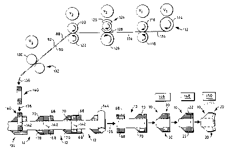
Referring now to Fig. 6, there is schematically illustrated one
process operated in accordance with the principles of the present
invention. Supply roll 112 supplies a continuous length of an
elastic material or a composite elastic material 114 between a pair
of nip rolls 116, 118. Supply roll 112 and nip rolls 116, 118 have
the same rotational velocity V~. Between supply roll 112 and nip
rolls 116, 118, composite elastic material 114 is in a substantially
untensioned state. Composite elastic material 114 is delivered
between chill roll 120 and idler roll 122, both of which have a
rotational velocity VZ that is greater than V~. Thus, between nip
rolls 116, 118, and chill roll 120 and idler roll 122, composite
elastic material 114 is in an extended, tensioned state due to the
described difference in rotational velocities. By varying the
rotational velocity of nip rolls 116, 118 and/or chill roll 120/idler
roll 122, the length of and tension on composite elastic material 114
can be selectively controlled or varied. Between nip rolls 116, 118
and chill roll 120, idler roll 122 are pressure roll 124 and idler
roll 126, which have a rotational velocity V2, the same as chill roll
120 and idler roll 122. Pressure roll 124 includes a pair of
pressure sleeves 128 for selectively inhibiting temporarily, by
compression, those portions of composite elastic material 114 that
pass between a pressure sleeve 128 and idler roll 126.
Chill roll 120 may be used to enhance the treatment of composite
elastic material 114. For example, the temporarily inhibited portion
- 24 -
~134~9~
of composite elastic material 114 is chilled when it contacts the
surface of chill roll 120, which causes an increase in the period of
time that the portion is inhibited. Temporary inhibition may be
prolonged, for example, from about 2 to about 5 seconds by contact
with chill roll 120 for a period of about 1/4 to about 1 1/2 seconds.
Greater contact times will result in longer periods of inhibition.
Chill roll 120 is maintained at a temperature lower than the
temperature of the temporarily inhibited portion of composite elastic
material 114. Temperatures from about 60 degrees Fahrenheit to about
33 degrees Fahrenheit have been found practical, although lower
temperatures may be used.
After chill roll 120 and idler roll 122, composite elastic material
114 is delivered to anvil roll 130 and knife roll 132, which have a
rotational velocity 113 that is less than 11z. Because of this
difference in rotational velocities between chill roll 120 and knife
roll 132, composite elastic material 114 will be in a substantially
untensioned state. This allows the portion of composite elastic
material 114 that was not temporarily inhibited to contract, thereby
forming those portions that correspond to elastic side portions 88 of
waistband 32 (Fig. 2). Similarly, the temporarily inhibited portion
corresponds to front and back portions 90, 92 of waistband 32.
As will be explained hereafter, composite elastic material 114 has a
width that is twice the width of waistband 32, and has an elasticity
of about 180%. Between rolls 116, 118 and rolls 120, 122, composite
elastic material 114 is extended to an elongation of about 67%, and
at this elongation passes between pressure roll 124 and idler roll
- 25 -
CA 02134595 2004-04-23
126 to be compressed by a pressure sleeve 128 and idler roll 126,
thereby having its elasticity selectively inhibited temporarily.
Between rolls 120, 122, and rolls 130, 132, the uncompressed portions
have substantially recovered to their original elasticity of about
180%.
A continuous partially elastic substrate 134 is continuously moving
in a first direction of travel, as illustrated by arrow 136.
Substrate I34 can be any type of partially elastic material for
manufacturing various products, such as those earlier described. In
this specific example, substrate 134 comprises a continuous length of
partially finished elastic pant bodies 12, in which each includes
front and back elastic side members 68, 70 that are extensible in a
direction generally transverse to the direction of arrow 136.
After being cut into select lengths by knife roll 132 and anvil roll
130, individual lengths 140 of composite elastic material 114 are
delivered in a direction, illustrated by arrow 138, generally
transverse to the first direction 136 of travel of continuous
partially elastic substrate 134. One method and apparatus that can
be used to accomplish this is described in U.S. Patent No, 4,608,115,
issued August 26, 1986, to Schroth et al.
Each individual length 140 of composite elastic material 114 is
suitably intermittently joined, such as by ultrasonic, heat, or
adhesive point bonding to continuous partially elastic substrate 134
at selected locations thereof. The selected locations correspond to
- 26 -
CA 02134595 2002-07-15
the transverse line along which continuous partially elastic
substrate 134 will be cut in order to produce individual disposable
absorbent garments 10. The cut line 142 corresponds to front edge 44
(Fig. 5) and back edge 48 of two garments 10.
After an individual length 140 of composite elastic material 114 has
been joined to continuous partially elastic substrate 134, substrate
134 is delivered to a cutting station 144, at which substrate 134 is
cut along cut line 142. The cutting station 144 can be any suitable
apparatus known in the art.
This cutting of substrate 134 results in individual, partially
finished disposable absorbent garments 10. These garments 10 are
then delivered to a folding and aligning station 146 where garment 10
will be folded with its outer edges 50, 58 (Fig. 5) aligned for
subsequent bonding. One apparatus and method for aligning outer
edges 50, 58 is described in U.S. 5,046,272 issued September 10,
1991, to Vogt et al.
Thereafter, a folded and aligned garment 10 proceeds to bonding
station 148 where the aligned outer edges 50, 58 are bonded to form
seams 22. The bonding can be accomplished in any suitable manner,
such as by rotary ultrasonic bonding. Finally, the bonded garment 10
proceeds to activation station 150 where temporarily inhibited front
and back portions 90, 92 are activated, by treating with heat for
example, to recover their elasticity.
_ 27 _
~13~~~
In the finished disposable absorbent garment 10, elastic side
portions 88 of waistband 32 have, in this example, substantially the
same elasticity as elastic side sections 20, while front and back
portions 90, 92 provide an elasticity in the range of about 30% to
about 60% to non-elastic front and back segments 84, 86. The amount
of elasticity of back segments 84, 86 will depend on several factors,
such as the materials used and manufacturing operating conditions.
Fig. 7 illustrates a modification to the method illustrated in Fig.
6. Supply roll 112 provides a continuous supply of heat-
elasticizable material 152 to nip rolls 116, 118. Supply roll 112
and nip rolls 116, 118 have a rotational velocity V~. Material 152
is conveyed to roll 120', which may or may not be chilled, and idler
roll 122, which have a rotational velocity V4 less than 11~.
Activation station 154 is positioned between rolls 116, 118 and rolls
120, 122, and directs a stimulus, for example, heat radiation,
against heat-elasticizable material 152 to elastically activate
selected portions thereof. As these portions are elastically
activated, they "shrink" in length and become elastic. Thus, the
rotational velocity of rolls 120, 122 needs to be less than the
rotational velocity of rolls 112, 116, 118. By selectively
controlling activation station 154, material 152 is provided with
"activated" elastic portions of desired length, as well as
"non-activated" non-elastic portions of desired length. The
"activated" portions correspond to elastic side portions 88 (Fig. 2),
and the "non-activated" portions correspond to front and back
portions 90, 92 of waistband 32. The result is a continuously moving
material 152 that includes alternating elastic and non-elastic
_ 28 _
~134~9
portions. Material 152 then may be selectively cut to provide
individual lengths 140 of an elastic material. Thereafter, the
individual lengths 140 of elastic material can be suitably joined to
substrate 134 in a manner similar to that described above with
reference to the process represented by Fig. 6. Substrate 134 can
then be cut at station 144, folded and aligned at station 146, bonded
at station 148, and activated at station 150.
Although the above description of a process of the present invention
was made in relation to a disposable training pant, the present
invention can be used to make other types of products or items where
it is desired to join an elastic material to a continuously moving,
partially elastic substrate. Thus, while this invention has been
described as having a preferred embodiment, it will be understood
that it is capable of further modifications. This application is
therefore intended to cover any variations, equivalents, uses, or
adaptations of the invention following the general principles
thereof, and including such departures from the present disclosure as
come or may come within known or customary practice in the art to
which this invention pertains and fall within the limits of the
appended claims.
_ 29 _