Language selection

Search

Patent 2135723 Summary

Third-party information liability

Some of the information on this Web page has been provided by external sources. The Government of Canada is not responsible for the accuracy, reliability or currency of the information supplied by external sources. Users wishing to rely upon this information should consult directly with the source of the information. Content provided by external sources is not subject to official languages, privacy and accessibility requirements.

Claims and Abstract availability

Any discrepancies in the text and image of the Claims and Abstract are due to differing posting times. Text of the Claims and Abstract are posted:

  • At the time the application is open to public inspection;
  • At the time of issue of the patent (grant).
(12) Patent Application: (11) CA 2135723
(54) English Title: MEASURING SYSTEM FOR MONITORING BUILDINGS, TERRAIN SECTIONS OR THE LIKE
(54) French Title: SYSTEME DE MESURE POUR LA SURVEILLANCE DE BATIMENTS, DE TERRAINS ET AUTRES ESPACES ANALOGUES
Status: Deemed Abandoned and Beyond the Period of Reinstatement - Pending Response to Notice of Disregarded Communication
Bibliographic Data
(51) International Patent Classification (IPC):
  • G01P 13/00 (2006.01)
  • G01B 11/16 (2006.01)
  • G01M 11/08 (2006.01)
  • G01N 21/84 (2006.01)
  • G02B 6/028 (2006.01)
(72) Inventors :
  • LEßING, RAINER (Germany)
(73) Owners :
  • SICOM GESELLSCHAFT FUR SENSOR- UND VORSPANNTECHNIK MBH
(71) Applicants :
  • SICOM GESELLSCHAFT FUR SENSOR- UND VORSPANNTECHNIK MBH (Germany)
(74) Agent: SMART & BIGGAR LP
(74) Associate agent:
(45) Issued:
(22) Filed Date: 1994-11-14
(41) Open to Public Inspection: 1996-05-15
Availability of licence: N/A
Dedicated to the Public: N/A
(25) Language of filing: English

Patent Cooperation Treaty (PCT): No

(30) Application Priority Data: None

Abstracts

English Abstract


The measuring system for monitoring buildings, terrain
sections or the like consists of a beam waveguide bending sensor
which has a multimode beam waveguide (GI) and is disposed in the
shape of a loop. Several arc-shaped sensor sections (S) are
disposed between support plates, which are movable in respect to
the sensor sections and and fixedly connected with areas of the
building or terrain sections. A light source and light receiver
with an evaluation device for light subduing values are connected
to the beam waveguide bending sensor. The beam waveguide bending
sensor is disposed in the form of several loops. The beam
waveguide bending sensor consists of gradient-index-multimode beam
waveguide sections (GI) and step-index-multimode beam waveguide
sections (SI) connected therewith, wherein the sensor sections (S)
are formed by the gradient-index-multimode beam waveguide (GI).


Claims

Note: Claims are shown in the official language in which they were submitted.

The embodiments of the invention in which an exclusive property or privilege
is claimed are defined as follows.
1. A measuring system for monitoring buildings, terrain
sections or the like
with a beam waveguide bending sensor which has a multimode
beam waveguide (GI) and is disposed in the shape of a loop,
has several arc-shaped sensor sections (S) between support
plates, which are movable in respect to the sensor sections and are fixedly
connected with areas of the building or terrain sections, and
with a light source and light receiver with an evaluation
device for light subduing values connected to the beam waveguide
bending sensor,
characterized in that
the beam waveguide bending sensor is disposed in the form
of several loops and
the beam waveguide bending sensor consists of gradient-
index-multimode beam waveguide sections (GI) and step-index-
multimode beam waveguide sections (SI) connected therewith,
wherein the sensor sections (S) are formed by the gradient-index-
multimode beam waveguide (GI).
2. A measuring system in accordance with claim 1,
characterized in that
each arc-shaped sensor section (S) is guided by reversers
(11) with an exterior surface with a bending radius, and the
reversers are connected with the ends (6, 7), which face each
other, of the support plates (2, 3).
-6-

3. A measuring system in accordance with claim 1 or 2,
characterized in that
each support plate (2, 3) has a receiving chamber (17, 21)
for the beam waveguide (15) with inlet (16, 20) and outlet (27),
wherein the beam waveguide rests against the interior wall
of the receiving chamber.
4. A measuring system in accordance with claim 3,
characterized in that
the receiving chamber (17, 21) has interior concentric
walls for inner loops of the beam waveguide (15).
5. A measuring system in accordance with claim 1,
characterized in that
the beam waveguide (15) is fastened on the support plates
(2, 3) on both sides of the sensor path S.
-7-

Description

Note: Descriptions are shown in the official language in which they were submitted.


- 213~723
Measuring System for Monitoring Buildings,
Terrain Sections or the Like
The invention relates to a measuring system for monitoring
buildings, terrain sections or the like, having the
characteristics of the preamble of claim 1.
A measuring system for monitoring buildings, having a beam
waveguide bending sensor, is known from DE-PS 39 02 997. In this
case the beam waveguide bending sensor as a whole consists of a
gradient multimode beam waveguide GI. This beam waveguide is
disposed in the shape of a loop. It has two arc-shaped sensor
sections S between carriage-like support sections which can be
moved toward each other and whose support plates are connected
with the sections of the building to be checked. A light source
is connected to one end of the beam waveguide and a light receiver
with evaluation devices for light subduing values to the other
end. In this case it is disadvantageous that such a measuring
system can be possibly too insensitive and that the sensitivity
can also not be considerably increased. This is essentially
attributable to the fact that in such a beam waveguide the bending
sensitivity is weakened after bending. In connection with the
described measuring system there is repeated curving of the beam
waveguide, therefore the bending sensitivity is greatly reduced.
On the other hand, a step-index beam waveguide is known,
which has a lesser bending sensitivity. However, it is not usable
as a beam waveguide for the sensor path of the described measuring
system.
It is the object of the invention to provide a measuring
system for monitoring buildings, terrain sections and the like,
whose sensitivity is considerably increased.

- 2135723
This object of the invention is attained by means of the
characterizing features of claim 1.
The measuring system in accordance with the invention has a
considerably increased sensitivity. This is based on the fact
that the bending sensitivity of the sensor section with the
gradient multimode beam waveguide is maintained by downstream
step-index beam waveguide sectors.
In accordance with an embodiment of the invention, each
arc-shaped sensor section is guided by reversers whose exterior
surfaces have a bending radius. The reversers are connected with
ends of the support plates facing each other. Because of this the
beam waveguide extends free of kinks on the exterior surface.
In accordance with a further embodiment of the invention,
each support plate has a receiving chamber for a beam waveguide
with inlets and outlets, wherein the beam waveguide can rest free
of kinks and secured on the interior wall of the receiving
chamber.
In accordance with a further embodiment of the invention,
the receiving chamber for the beam waveguide can have concentric
interior walls for inner loops of the beam waveguide.
The invention will be described in detail below by means of
an exemplary embodiment shown in the drawings. The drawings show:
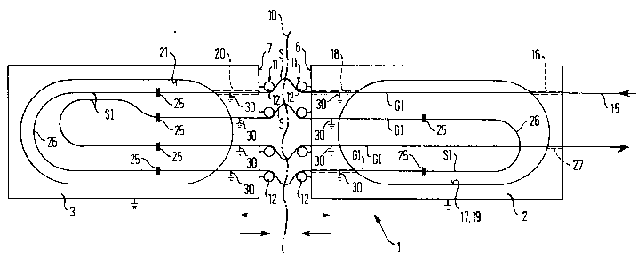
A schematic top view of a measuring system in accordance
with the invention.

2135 723
The measuring system 1 can be used in buildings, terrain
sections, for example fallen rocks, or the like.
It comprises two support plates 2, 3. These are fixedly
connected with the building areas, which is schematically
indicated in the drawings. The zone of a building or, for example
a fissure 10 in the terrain, to be monitored extends between the
two facing ends 6, 7 of the support plates 2, 3.
The support plate 2, 3 is preferably rectangular in shape.
It consists of a rigid metal body.
Respectively four reversers 11 oriented toward each other,
for example in the shape of tangs 12, are for example provided at
the ends 6, 7. These tangs 12 are fixedly connected with the ends
6, 7. They have an exterior surface with a bending radius.
The beam waveguide 15 is connected to a light source, not
shown, which feeds light in the direction of the arrows shown.
Preferably the beam waveguide 15 is led via a guide 16, only
indicated by dashed lines, to a receiving chamber 17. The
receiving chamber can have an oval shape, for example, as shown.
It is formed by milled cut-outs in the support plate 2.
Although, as shown, the beam waveguide 15 can cross the
receiving chamber 17 in a straight line and ,guided to the other
end, can exit via an outlet 18 at the support plate end 6, it is
preferred to guide the beam waveguide 15, freely resting against
the interior wall 19 of the receiving chamber 17, possibly once
around the receiving chamber and only then to guide it to the
outlet 18.

1 2135723
Then the beam waveguide 15 freely extends via the tang 12
and guided by its exterior wall in the form of an arc-shaped
sensor path S to the oppositely located tang 12. Guided along a
bending radius by the exterior surface thereof, the beam waveguide
15 enters the receiving chamber 21 of the other support plate 3
via a guide 20. In the region of the receiving chamber 21, the
beam waveguide 15 of the gradient beam waveguide (GI) type is
connected by means of a splice 25 - only shown schematically -
with a beam waveguide of the step-index beam waveguide (SI) type.
The beam waveguide 15 then is furthermore disposed in a
loop with the reverser 26. Here, again - as in the receiving
chamber 17 - it can also be guided freely resting against the wall
of the receiving chamber 21. In ~he outgoing loop section, the
beam waveguide 15 iS again/via a splice 25 with a beam waveguide
15 of the type GI. The latter returns via a second sensor section
S, which is embodied as described above, into the receiving
chamber 17 of the support plate 2. Here, too, an inlet is
provided. In the receiving chamber 17, the beam waveguide 15 of
the type GI is connected by a splice with a beam waveguide 15 of
the type SI. The latter is guided by means of a reverser 26 and a
splice 25 with a connecting beam waveguide 15 of the type GI to a
further sensor path S. From there, the beam waveguide lS of the
type GI extends via a guide into the receiving chamber 21. There,
it is connected via a splice 23 with a succeeding beam waveguide
section SI. Finally, the beam waveguide GI returns to the
receiving chamber 17 via a further splice 25 with a further sensor
path S, and from there via an outlet 27 over the support plate 2
to the outside to a light receiving and evaluation unit, not
shown.

i 2135723
The inner loops of the beam waveguide can also rest against
a concentric interior wall, not shown, in the receiving chambers
17 to 21.
Instead of guiding the beam waveguide 15 in a double loop,
as shown, it can also be guided in arbitrary multiple loops. The
measuring sensitivity can be increased by the increasing number of
loops. The limit is provided in that the exiting subdued light is
reduced more and more and that possibly expensive transmitting and
receiving devices must be employed.
It is of importance that a beam waveguide of the type GI is
used in the area of the sensor section S and that a beam waveguide
section of the type SI adjoins this, which/the effect of the
preceding beam waveguide sections, in which the light is
concentrated because of bending, afterwards is again homogeneously
distributed over the beam waveguide cross section by the beam
waveguide section SI. Types GI are to be used for the inlet and
outlet sections of the beam waveguide 15.
The beam waveguide 15 must be fixedly connected with the
support plates 2, 3 on both sides of the sensor path S, for
example by adhesion. Adhesive spots 30 are schematically shown.

Representative Drawing
A single figure which represents the drawing illustrating the invention.
Administrative Status

2024-08-01:As part of the Next Generation Patents (NGP) transition, the Canadian Patents Database (CPD) now contains a more detailed Event History, which replicates the Event Log of our new back-office solution.

Please note that "Inactive:" events refers to events no longer in use in our new back-office solution.

For a clearer understanding of the status of the application/patent presented on this page, the site Disclaimer , as well as the definitions for Patent , Event History , Maintenance Fee  and Payment History  should be consulted.

Event History

Description Date
Inactive: IPC from MCD 2006-03-11
Time Limit for Reversal Expired 1999-11-15
Application Not Reinstated by Deadline 1999-11-15
Deemed Abandoned - Failure to Respond to Maintenance Fee Notice 1998-11-16
Letter Sent 1998-02-24
Reinstatement Requirements Deemed Compliant for All Abandonment Reasons 1998-02-17
Deemed Abandoned - Failure to Respond to Maintenance Fee Notice 1997-11-14
Application Published (Open to Public Inspection) 1996-05-15

Abandonment History

Abandonment Date Reason Reinstatement Date
1998-11-16
1997-11-14

Maintenance Fee

The last payment was received on 1998-02-17

Note : If the full payment has not been received on or before the date indicated, a further fee may be required which may be one of the following

  • the reinstatement fee;
  • the late payment fee; or
  • additional fee to reverse deemed expiry.

Please refer to the CIPO Patent Fees web page to see all current fee amounts.

Fee History

Fee Type Anniversary Year Due Date Paid Date
Reinstatement 1998-02-17
MF (application, 3rd anniv.) - small 03 1997-11-14 1998-02-17
Owners on Record

Note: Records showing the ownership history in alphabetical order.

Current Owners on Record
SICOM GESELLSCHAFT FUR SENSOR- UND VORSPANNTECHNIK MBH
Past Owners on Record
RAINER LEßING
Past Owners that do not appear in the "Owners on Record" listing will appear in other documentation within the application.
Documents

To view selected files, please enter reCAPTCHA code :


To view images, click a link in the Document Description column. To download the documents, select one or more checkboxes in the first column and then click the "Download Selected in PDF format (Zip Archive)" or the "Download Selected as Single PDF" button.

List of published and non-published patent-specific documents on the CPD .

If you have any difficulty accessing content, you can call the Client Service Centre at 1-866-997-1936 or send them an e-mail at CIPO Client Service Centre.


Document
Description 
Date
(yyyy-mm-dd) 
Number of pages   Size of Image (KB) 
Description 1996-05-15 5 190
Cover Page 1996-07-05 1 17
Abstract 1996-05-15 1 26
Claims 1996-05-15 2 53
Drawings 1996-05-15 1 18
Representative drawing 1998-02-26 1 13
Courtesy - Abandonment Letter (Maintenance Fee) 1997-12-15 1 186
Notice of Reinstatement 1998-02-24 1 172
Courtesy - Abandonment Letter (Maintenance Fee) 1998-12-14 1 184
Fees 1998-02-17 2 63
Fees 1996-12-04 1 41
Fees 1996-12-04 1 26
Courtesy - Office Letter 1995-01-20 1 39