Note: Descriptions are shown in the official language in which they were submitted.
W093/22899 ~1 3 ~ 7 ~ 5 PCT/US93/04578
'~ PLANTING TRAY
BACKGROUND OF T~E INYENTION
Technical Field:
The present invention concerns a planting tray.
More particularly, the present invention concerns a
planting tray wherein the plants and the tray may be
planted in the ground without removing the plant from the
tray.
Background Art:
Horticulturists practice the techni~ue of
germinating seeds in controlled environments, such as
greenhouses, nurseries, and homes. By giving young plants
6ufficient light, moisture and nutrients at the critical
early developmental stage, the plant can develop a proper
root system and become sturdy. The plant is then
transferred to, usually, an outdoor environment, such as a
garden.
There are, however, problems associated with this
technique. The transplanting of the seedling may induce a
trauma in the plant, particularly to the root system. This
trauma can interrupt the flow of nutrients to the plant.
This will stunt the growth of the seedling or, in the
extreme ca~e, kill the plant. Other problems encountered
include the loss of dirt, which can damage the root system,
and possible physical injury to the plant. Thus, there is
a need for a device to allow seeds to germinate while
eliminating the damages incurred when transplanting.
One approach to satisfying this need is found in
U.S. Patent No. 4,918,863, issued April 24, 1992 to
Youssef. Youssef teaches a method for planting and
germinating seeds, the seeds being planted in a germinating
soil mix. The seeds and soil mix are held within the
enclosures of an expandable honeycomb structure. The
honeycomb is laid over a soil or similar medium. The seeds
2 ~ ~ ~5 745 ;
germinate in a defined, weed-free environment, with the root system growing
dowJ~w~ly into the soil.
Youssef, ho..~ r, re~lui~es deplo~--.ent of the honeycomb structure over
the intP~t3e~ soil ..~A;...~., so that the roots may grow thereinto. Thus, except
for a brief period directly after the pl~ntinE of the seeds, Youssef is not usable
indoors or in most controlled envi~~ ntC. rulll,er, the honeycomb structure
loses dirt through its bottom if moved after dirt and seeds have been deployed
therein. While Youssef does ~;S~ 5 the use of a plywood board as a base
during indoor germination, the same ~lifficl~lties of disrupting the soil, and
thereby the root system of the se~linE~ and possible physical damage to the
seedling, are el.co~ tcr~. Finally, Youssef forces developmenl of the root
system in a vertical direction, excludin~ horizontal growth. For many plants,
this is decidedly a harmful and unfavorable situation.
What is needed is a device that will allow tne gerrnination of a seeAling
in an enclosed environl,.e.ll and further allow that direct pl~ntinp of the see~ ng
to a pc....~-e!-l soil ..~e~i.J~ witnout nr,ce.5sil;.~;ng transplantation from the
device. It is to this need that the p.esent invention is directed.
DISCLOSURE OF THE INVENTION
Accor~ g to an object of an aspect of the l~lesent invention, there is
provided a planting tray for ~l...in~l;n~ seeds and starting young plants and
which comprises:
(a) a flat me-mber having a plurali~y of operlin~c;
(b) a plurality of b~skete having an interior,
the b~cketc being formed with the flat l..el..~el such that one openin~ of the flat
member communic~tes with the interior of one basket, the basket having a
plurality of ~lroldtions formed therein to allow roots of the plant to grow
therethrough, wherein the tray and the at least one plant are directly plantable in the ground.
The openings of the flat ~.~e~ c- of the tray of the prcsenl invention may
be fol,-led in a matrix, the matrix comprising a first coordinate and a second
coordinate, the matrix being fol,--ed such that one coo~inate is even and the
" ~. , .
t
3 2 ~ ~5 74~
other coordinate is odd.
The ~r~sent invention may further be formed such that no two baskets
within either cool.lil~ are adjacent. The tray may further be formed of a
biodegradable material.
According to an object of an aspect of the plesent invention, there is
provided a p1snting tray for ge,.~;n~;n~ seeds which comprises:
(a) a rectangular flat ..~e-.~ber foll,led of a biodegradable material, the
flat melnber having a plurality of open;n~s fanned therein in a matrix, the
matrix having a first and a second coordinate, one coordinate being an even
.e~l and the other coordinate being an odd ~ lllc~l; and
(b) a plurality of bscl~etc comrrices a plurality of t~r~d side walls
and a bottom, the side walls de-fining an upper opening, the side walls and the
bottom cou~laLing to define an intenor, the side walls and the bottom having
a plurality of p~,rorations forrned therein, to allow roots of the plant to growthel~ through, the b~c~ets being follucd with the flat member such that one
openin~ of the flat Illelnl)~r is in col~ J~;c~tion with the interior of one basket;
wherein no two b~Cl~çtc are deployed with adjacent ope~;n~.c within
either coordinate of the matrix, wherein the tray and the at least one plarlt are directly
plantable in the ground.
According to another object of an aspect of the invention, there is
provided a tray for gernnin~tin~ seeds and starting young plants, the tray and
plants being directly pl~nt~le in the ground, the tray colll~l;3es:
(a) a flat member having a plurality of openingc fo~,l-cd therein, the
ope~in~C being fo,lllcd in a matrix having a first coordinate and a second
coor~inate; and
(b) a plurality of b~S~tc having at least one side wall and a bottom
coo~.ating to define an open interior, the b~cl~ptc being follllcd with the flatmember such that one opening of the flat member is in con-mul~ication with the
interior of one basket, each basket having a plurality of pelrorations formed
therein to allow roots of tne plant to grow tllclell~o.lgh, the b~Ql~PtC being
formed to the flat n~ember such that no two b~cl~p-tc are formed in
.. .
~ ~ .
,....
3a ;~ ~ 35 74 5
conl,mlnication with two ope~ingc adjacent in either coor~inate of the matrix.
According to another object of an aspect of the invention, there is
provided a tray for gerrnin~ting seeds and stanting young plants, the tray
COmrri~ing
(a) a flat .~.e ,.1~ having a plurality of opcl~;ng~ ~IIlled therein, the
op~nings being fanned in a matrix having a first cooniinate and a second
coordinate; and
(b) a plurality of basL-PtC having at least one side wall and a bottom
coope-aling to define an open int~rior, the baskets being formed with the flat
member such that one opening of the flat ~lle~nber is in cG.. ~ ;cation with the
interior of one basket, the bscl~çtc being formed to the flat member such that
no two b~ck~ts are formed in co,~ tion with two openings adjacent in
either coordinate of the matrix, wherein the tray and the plants are directly plantable in the
ground.
According to a further object of an aspect of the invention, there is
provided a plurality of inle~ ble trays for gerrnin~ting seeds and young
plants and later impl~nt~tion in the ground, the trays comprises:
(a) a first tray having a flat Illel,lber, the flat member having a
plurality of opel~in~c therein in a matrix having a first coordinate and a second
coordinate, the tray further having at least one basket fo~ll,ed thereto, each
basket comprises at least one side wall and a bottom coopelating to define an
interior, the interior of each basket being in co~ tion with one opening
of the flat member, each basket having a plurality of perforations formed
therein to allow plant roots to grow the~lllrough; and
~ b) at least one additional tray, the at leact one additional tray having
a flat member, the flat ~--e...ber having a plurality of openings fo~-.-ed therein
in a matrix having a first coordinate and a second coo~dindte, the at least one
additional tray further having at least one basket fol...ed thereto, each basketcomprising at least one side wall and a bottom coo~lating to define an interior,
. ~
~ - 3b - ~ '¦ 3 ~ ~ ~Ç ~5 ~
the interior of each basket being in communication with one opening of the flat
member, each basket having a plurality of pelrGlalions formed therein;
wherein the at least one additional tray is stack~ble atop the first tray
such that the baskets of the at least one additional tray protrude through the
openings of the first tray and the flat member of the at least one additional tray
rest upon
the flat member of the first tray, and wherein further no basket of the at least10 one additional tray protrudes through an opening of the first tray which is in
communication with any basket formed thereto.
According to still a further object of an aspect of the invention, a
plurality of interstackable trays for germin~ting seeds and starting young plants,
comprises:
(a) a first tray which comprises:
(1) a flat member having a plurality of openings formed
therein, the openings being formed in a matrix having a first coordinate and a
second coordinate; and
(2) a plurality of baskets, each basket having at least one side
20 wall and a bottom cooperating to define an open interior, the plurality of
baskets being formed integrally with the flat member such that one opening of
the flat member is in communication with the interior of one basket;
(b) at least one additional tray, each additional tray comprises:
(1) a flat member having a plurality of openings formed
25 therein, the openings being formed in a matrix having a first coordinate and a
second coordinate; and
(2) a plurality of baskets having at least one side wall and a
bottom cooperating to define an open interior, the plurality of baskets being
formed integrally with the flat member such that one opening of the flat
30 member is in communication with the interior of one basket;
3c ~ ~3~7~5 ~
- wherein the trays and their ~ssoci~teA baskets may be st~r~eA one upon
~nother and no basket at any one matrix location of any one tray will coincide
with a b~ket at the same matrix location of any additional tray, wherein the tray and the
plants are directly plantable in the ground.
For a more complete unde.~ din~ ofthe pr~sent invention, the reader
is ,~rclr~i to the following ~e~iled ~CS~ )!;Q'l, which should be read in
conjunction with the ~~col.~pa-.ying drawing. Throughout the following
desrrirtion and in the drawings, like .~f~ nce nuu,cldls refer to like parts.
BRIEF DESCRIPrION OF THE DRAWINGS
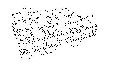
Figure 1 is a p~a~cli~e view of the pl~nting tray of the ~rese,
invention;
Figure 2 is a top view of the pl~nting tray of the pr~se-ll invention;
Figure 3 is a pe~cti~e view of two pl~nting trays of the ylese~lt
invention, the trays being partially intermesl~ for storage in a controlled
en~ orl,lle.lt;
Figure 4 is a side view of the partially intermesherl p!~ntin~ trays of
Figure 3;
Figure S is a pel~cclive view of a F!~nting tray basket with holes in the
sides and bottom; and
Figure 6 is a side cross-sectionql view of a planting tray basket with
partially tapered sides.
BEST MODE FOR CARRYING OVT 1 HE; INVENTION
Referring now to Figures 1-6, there is shown ehe plesent invention, to
wie, a ~l~ntin~ eray 10 for use in a conerolled environ.llenl and later deployment
in a ~~ n~--t soil ,-.rAi~n. (not shown). The tray 10 comprises a flat member
12 and a pluraliey of b~cl~ets 14.
,.. ..
: ,~
' ~
.-
W O 93/22899 ~ 1 3 S 7 ~ ~ PC~r/US93/04578
The flat member 12 is substantially planar and
rectangular. If desired, a different shape for the member
12 could be selected. A plurality of openings 16 are
formed within the flat member 12. The openings 16 are
arranged in a matrix formation, the matrix comprising a
first coordinate or rows R and a second coordinate or
columns C. It is noted that the designation of rows and
columns is not absolute, but rather are selected for
illustrative purposes to denote the two coordinates of a
two-dimensional matrix. Thus, it is seen that where
reference is made to rows that columns could be implied,
and where columns are referenced rows could be implied.
What is important to note is that there is a first
coordinate and a second coordinate for the matri~.
The arrangement of the matrix of openings is
critical for the practice of the present invention in its
preferred embodiment. Specifically, the number of openings
in each row must be even if the number of openings in each
column is odd. ~quivalently, the number of openings in
each row must be odd if the number of openings in each
column is even. This arrangement allows for the
intermeshing or stacking of two identical trays 10.
Intermeshing affords efficient spacial deployment in a
controlled, above-ground environment, as will be more fully
described herein further below.
The baskets 14 are formed in a generally cubic
shape, having an upper opening 28, at least one side wall
30 snd a bottom 32. As shown in Figures 1-4, a plurality
of side walls 30 are formed with a taper. The side walls
30 define the upper opening 28, such that the open top 28
is of a greater surface area than the bottoms 32.
Alternately, the side walls 30 could be formed without a
taper, effecting a basket 14 having a perfectly cubic
~ -s-
structure. A substantially cylindrical structure, thus effecting only one side
wall as an equivalent structure. The important criteria is the ability of the
structure to hold soil or other planting medium therein and to be stackable
without regard to geometric configuration.
The third configuration is to have the side walls formed partially
straight with the rem~in~ier of the wall having a taper extending to the bottom
of the basket, as shown in Figure 6.
The side walls 30 and the bottom 32 are formed of material
identical to the flat member 12. The side walls 30 and bottom 32 have a
10 plurality of perforations 34 formed therein. The perforations 34 are depictedin Figure 5 as a plurality of intersecting slits disposed around the side walls and
bottom 32. The perforations 34 could alternately comprise a multiplicity of
apertures or other similar structure, as desired. The perforations 34 are small
enough to prevent soil 20 held within the interior of the basket 14 from
15 escaping ther~ rough, yet large enough to allow the roots of the plant to grow
therethrough.
The side walls 30 and the bottom 32 cooperate to define an
interior 56 therein. The interior 36 commllnicates with the open top 28 of the
basket 14. Each basket 14 is affixed to the flat member 12 such that one
20 opening 16 of the flat member 12 is in co"""ll.,ication with the opening 28 of
the basket 14, and may therefore co"~",ll~,icate with the interior 36 of the
basket 14. By this affixation, a user of the tray 10 may place soil 20 or other
planting medium into the interior 36 of the basket 14, through the opening 16
in the flat member 12. A seed may then be placed within the soil 20 for
25 germination. It is critical that the perforations 34 be small enough to prevent
the soil 20 held within the interior of the basket 14 from escaping therethrough,
yet large enough to allow the roots of the plant to grow there~ ough.
As can be seen in Figure 2, the tray 10 has a specific deployment
pattern for the baskets 14 to the flat member 12. Specifically, it can be seen
30 that in each row R of the tray 10, no two baskets 14 are affixed to adjacent
5a 2 ~ ~!5 7~5 ~
openings 16. Thus, we seen an arrangement of a basket, opening, basket,
ope~ng, etc. Similarly, the same
//~
,"/
W093/22899 ~1 3 ~ ~ 4 S PCT/US93/04578
arrangement is found in each column C of the tray 10, where
no two baskets 14 are affixed to any adjacent openings in
any column C.
INDUSTRIAL APPLICABILITY
The advantage of this deployment of baskets 14 on
the tray 10 can be seen in reference to Figure 3. There, a
lower tray, having a first end denoted 24 and a second end
denoted 26, the first end 24 being opposite of the second
end 26, has deployed thereabove a ~econd identical tray 10,
the second tray having a first end 124 and a second end
126, the first end 124 being opposite the second end 126.
The first end 124 of the second tray 10 is identical to the
first end 24 of the first tray, and likewise the second end
126 of the second tray is identical to the second end 26 of
the first tray. The carefully structured pattern of
deployment of the baskets 14 allows for the intermeshing of
the two trays, such that no two baskets connected to the
two trays will interconnect each other when the trays 10
are intermeshed. Thus, in the lower tray, each opening
will receive therethrough a basket attached to the upper
tray, and each opening having a basket thereunder will have
mounted thereabove an opening without a basket on the upper
tray. This design allows for the intermeshing or
overlaying of two trays, such that space may be efficiently
used during the indoor utilization of the tray 10. When
permanent implantation in a soil medium outside the
controlled environment is desired, the trays 10 may be
separated easily and implanted individually in the ground.
This design allows sufficient growing space between each
deployed seedling in the tray 10.
It is to be noted that to form a planting tray 10
having baskets 14 affixed thereunder does not re~uire the
pattern of the preferred embodiment of the present
invention. Failure to utilize this pattern, however, will
W093/22899 2 1 3 5 7 ~ .5 PCT/US93/04578
_ ..
,~ _
result in trays that cannot be intermeshed for effective
indoor storing. It is noted that it would be possible to
form a tray having every opening having a basket
thereunder. This however would not allow sufficient
growing space for many plants, but is a less desirable
alternative.
Further, it is noted that the matrix combinations
can be different from that defined in the preferred
embodiment of the present invention. However, if different
embodiments are elected, such as an even number of rows and
an even number of columns, it is noted that the intended
intermeshing cannot effectively occur. This is because
these alternate deployments of the baskets would result in
the placement of plants over the same openings in every
tray, regardless of any rotation of tray orientation to
effect intermeshing, two coordinated deployment patterns
would be necessary. For example, in a matrix that has
three rows and three columns, there could be a design
having four baskets affixed to the flat member, and another
design having five baskets affixed to each opening. This,
however, would require the sale of the matching tray pairs
so that the intermeshing and we11-spaced plants could be
achieved. None of the aforementioned problems are
encountered when the matrix of the preferred embodiment is
utilized.
Thus, it is Doted that a seed can be planted in a
Z5 soil medium held within the basket of the tray. Once the
seed has germinated, and the young seedling has begun to
mature to the point where its root system is poking beyond
the perforations of the basket, the entire tray may be
transplanted into a permanent soil medium, whether that be
in an outdoor garden, a larger indoor planting container,
or in an enclosed greenhouse. The plant may therefore
~ ~ 3 ~i 7 4 ~ ~
_ 8
continue its growth without the trauma of being transplanted from the tray 10
This further allows the plant to grow through the tray 10, as the tray 10 will
not interfere with its growth. It is noted that in the prerelled embodiment the
tray 10 is formed of a biodegradable material. It is noted, however, that other
S suitable materials, such as plastic, could be utili7e~1. This would require the
tray be dug up and removed from the planting medium once the growing season
is completed.
It is to be noted that the prece~lin~ discussion has concerned the
~leferled utili7~tion of tray 10 of the present invention, namely to elimin~te the
10 trauma to the plants due to transplanting. The tray 10 of the present invention
can also be utili7e~1 by professional horticulturalists in the large scale
gerrnination of seeds of the growth of cuttings.
Large scale germin~tion occurs in flat beds having a great
plurality of small cups. A seed is germin~te~l in each cup. This facilitates the15 growth of a large number o plants in a small space. When greater space is
necess~ry for proper plant growth, the see~llings are transferred from the flat
bed to the tray 10 of the present invention. This allows the see-llin~.~ to fully
develop its root systems, although trauma may occur during transplantation.
The trays 10 may then be shipped to landscapers, nurseries or to be planted in
20 the ground.
Although preferred embodiments of the invention are described
herein in detail, it will be understood by those skilled in the art that variations
may be made thereto without departing from the spirit of the invention or the
scope of the appended claims.