Note: Descriptions are shown in the official language in which they were submitted.
X135965
PEAR FLOW METER
Background of the Invention
Many patients have respiratory problems, and it
often is advantageous for a doctor to be able to ascertain the
maximum peak rate of flow of a single forced expiration. It
is further desirable to have a small instrument readily used
by the patient himself to measure the peak flow. With a peak
flow meter it is possible for the patient to ascertain if his
peak flow rate remains at a more or less constant level, or if
it deteriorates over time, or if it improves.
Instruments for such use, especially by patients,
have been developed and are available commercially. However,
the instruments now on the market are not fully satisfactory.
They often have a member extending through a slot in a
cylindrical body and blown along the body by a patient's
exhalation into the cylindrical body. Such type of
construction allows for entry of contaminants into the body,
some of which leave residue that impairs movement of the
indicator member along the slot. Most such meters have
compressed scales which are difficult to read.
It is desirable that upon initial testing by the
doctor a marker be applied to the meter indicating desirable
range for the particular patient, as well as an improved range
and a poor or deteriorating range. Such markers as known
today are generally not satisfactory in that they are not
capable of representing a percentage above or below the
desirable range, since the desirable range for a given patient
might be quite different from that of another patient. All
._ X135965
2
that can be indicated is a fixed number above or below the
desirable range, but there will be a different percentage of
the desirable range depending upon where the desirable range
is located on the meter.
In accordance with known meters, as indicated above,
having a slot in the body through which the indicator moves,
an opportunity is presented for a patient accidentally to
block movement of the indicator with a misplaced finger. In
the usual case the indicator is moved by a piston within the
body, and as the piston travels along the body a progressively
greater amount of air is expelled through the slot as the
piston moves from rest position. Accordingly, the piston
travels to a point at which the venting of air from the body
balances a spring restraining the piston. Upon the cessation
of blowing, the piston is returned to rest position by the
spring, with the indicator remaining in the position reached
until manually returned to rest position. The indicator must
be of a relatively lightweight construction. If it is heavy,
it will have inertia, and even though the piston stops, the
indicator will continue to move according to its inertia, and
thus introduce false readings. However, if the indicator is
of extremely light weight and is exposed exteriorly of the
body through the slot in which it moves, then it must be
relatively fragile and susceptible to damage.
Objects and Summary of the Present Invention
It is an object of the present invention to provide
an improved peak flow meter which is inexpensive to produce,
long lived, and overcomes the deficiencies of the prior art.
.2135965
The invention provides a peak flow meter for
determining peak air flow of an exhaling patient comprising:
a hollow body for accommodating a flow of exhaled air there-
throught an indicator associated with said body and movable
relative to said body to a position along a scale on said
body, said position relating to a peak of the flow of exhaled
air through said body and said body having an internal area
related to said scale such that said scale represents a
logarithmic scale of the peak of the exhaled flow of air
through said body.
The invention also provides a peak flow meter for
determining a patient s expiratory flow, comprising: a hollow
body having an entering end and an exit ends an indicator
movable along said body from a first position in response to a
flow of air through said body from the entering end to the
exit ends movement balancing means for balancing movement of
said indicator along said body so that said indicator moves to
a second position along a scale on said body, said second
position related to a peak flow of air through said body, said
scale representing a logarithmic scale of the peak flow of
airy and a return mass for returning said indicator to said
first position independently of said movement balancing means.
The invention further provides a peak flow meter
comprising: a hollow body having an entering end for receiving
a flow of air and an exit ends an indicator associated with
said body and movable relative to said body to a position
along a scale on said body, said position related to a peak of
the flow of air through said body said scale being a
- 3 -
65902-63
2~ 35965
logarithmic scale extending longitudinally along the bodyt
indicator moving means associated with said body, separate
from said indicator, for moving said indicator from a first
position to a second position, said second position related to
a peak flow of air through said body and said
- 3a -
65902-63
2T35965
indicator and said indicator moving means mounted completely inside said
hollow
body.
Preferably the moving indicator is disposed entirely within the
confines of the elongated body, and there is no longitudinal slot in the body
as in
the prior art. The peak flow meter operates on a logarithmic scale, and has a
body expanding non-linearly to match such scale whereby progressively to
bypass
greater amounts of exhaled air as the piston moves away from rest position.
The
indicator is of extremely low mass, and does not overshoot. It includes the
provision of a weight or mass which is not attached to the indicator, but is
used for
returning the indicator to rest position.
The Drawings
The present invention best will be understood with reference to the
following specification when taken in connection with the accompanying
drawings,
wherein:
Fig. 1 is a side view of the peak flow meter of the present invention
as used by a patient;
Fig. 2 is a more detailed view similar to Fig. 1 on an enlarged scale;
Fig. 3 is a top view of the peak flow meter as shown in Fig. 2;
Fig. 4 is a left end view of the flow meter of Figs. 2 and 3;
Fig. 5 is a right end view of the flow meter;
Fig. 6 is a fragmentary exploded perspective view of the central
slitted tube of the flow meter and the parts associated therewith;
-4-
65902-63
r
X135965
Fig. 7 is a fragmentary longitudinal sectional view
of a portion of the flow meter;
Fig. 7A is a partial cross-sectional view as taken
substantially along the line 7A-7A in Fig. 7;
5 Fig. 8 is a fragmentary longitudinal sectional view
similar to Fig. 7 showing the parts in a different position of
operation;
Fig. 9 is an enlarged cross-sectional view taken
substantially along the line 9-9 in Fig. 2;
Fig. 10 is a cross-sectional view as taken
substantially along the line 10-10 in Fig. 2;
Fig. il is a fragmentary top view of the present
peak flow meter on a substantially enlarged scale showing the
logarithmic longitudinal scale of the flow meter;
Fig. 12 is a side view generally similar to Fig. 2
of an improved form of the invention;
Fig. 13 is a top view generally similar to Fig. 3
and corresponding to the improved form of the invention in
Fig. 12;
Fig. 14 is a left end view of the invention as shown
in Fig. 12;
Fig. 15 is a right end view of the form of the
invention shown in Fig. 12;
Fig. 16 is a sectional view as taken along the line
16-16 in Fig. 15;
Fig. 17 is an exploded perspective view of the right
or exit end of the invention as shown in Figs. 12-15, but
..m ~l~~~ss
6
inverted in order best to show certain features of the
invention;
Fig. 18 is a fragmentary side view partially in
section showing details of the marker and returning mass; and
Fig. 19 is a fragmentary top view corresponding to
Fig. 18.
Detailed Disclosure of the Illustrated Embodiment
Turning now in greater particularity to the
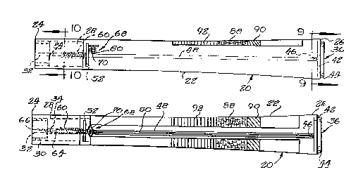
drawings, and first to Figs. 1-3, a peak flow meter 20
constructed in accordance with the principles of the present
invention comprises an elongated body 22 of hollow, tubular
construction. The body is smallest at its left or entering
end 24, and expands to a maximum diameter at its right or exit
end 26. The diameter and cross-sectional area do not expand
on a linear basis, but rather to match a logarithmic scale.
Hence, a longitudinal element of the body is not a straight
line, but is concave outwardly. Looking at this from a
mathematical standpoint, it is the generatrix that is
outwardly curved. The body 22 is circumferencially completely
closed, but is open at both ends. The body 22 preferably is
made of plastic material which is transparent at least above
the indicator shortly to be disclosed.
A plastic cylinder 28 is inserted in the left or
entering end of the body. The cylinder 28 preferably is
secured within the end of the body 22, such as by sonic or
chemical welding. The major portion of the cylinder is of
increasing inside diameter, but has a short portion at the
extreme left end of reduced inside diameter, as indicated at
X135965
30 (see also Figs. 4 and 10). A diametrical bar 32 extends
across the portion of reduced diameter at 30, and the length
of this portion. The bar is provided with a central
longitudinally extending projection or pip 34, the purpose of
which will be apparent shortly.
As will be seen in Fig. 2, the left or entering end
of the body 22 comprises a mouthpiece, and is designed to be
placed within a patient's mouth for exhalation. Considering
the direction of air flow through the peak flow meter 20, the
left end may also be considered as the upstream end, whereas
the right or exit end may be considered as the downstream end.
In any event, the right end is provided with a spider 36 (see
Figs. 5 and 9) having a central hub 38 and a plurality of
radial arms or spokes 40 extending to a circular rim 42 having
an outer diameter fitting snugly within the inner diameter of
the right end of the body 22. Outwardly of the rim there is
an integral cap 44 of greater diameter at its maximum equaling
the outer diameter of the end 26, and preferably tapering
inwardly therefrom. The spider 36 fits snugly and
frictionally within the right end 26 of the body. In this
embodiment of the invention it is not permanently secured to
the body. Similarly, the cylinder 28 at the left or entering
end could be held in place simply by a friction fit rather
than being permanently secured in place. The central hub 38
is provided with an axial projection or pip 46 which is
aligned with the pip 34.
All of the parts herefore referred to are
constructed of a resinous plastic material (commonly referred
~~35965
8
to as plastic) which is molded to the desired shape by known
molding methods. Axially of the body there is a metallic tube
48 extending nearly the entire length of the body and having
its opposite ends centered on and supported by the pips 34 and
46. The inside diameter of the tube is related to the outside
diameter of the pips so as to form a snug fit. A narrow
straight slit 50 extends longitudinally of the tube 48 from
end to end thereof. Attention should be paid to Figs. 6-8
along with Figs. 1-3 at this point. A piston 52 is slidable
on the tube 48 longitudinally of the tube. The piston
comprises a transverse disk 54 of fixed outside diameter less
than the internal diameter of the body 22 of the peak flow
meter 20. An integral cylinder 56 extends axially from the
disk 54 in the direction of the entering end 24 of the body.
The disk 54 and cylinder 56 have a common bore of very
slightly greater diameter than the outside diameter of the
tube 48 to allow sliding thereon. The disk and cylinder are
preferably molded of a suitable plastic.
The cylinder 56 immediately adjacent the disk 54 is
provided with a reduced diameter circumferencial notch 58. A
helical spring 60 tensionally urges the piston back toward the
entering end 24. The inside diameter of the spring 60 is
substantially greater than the outside diameter of the tube 48
so as to fit loosely there-about, and is of substantially the
same diameter as the outside diameter of the cylinder 56.
However, the last two turns of the spring 60, as indicated at
62 are of reduced diameter so as to grip within the notch 58,
and thereby attach the spring to the piston. The opposite end
-- X135965
9
of the spring is provided with an elongated portion 64 having
a re-entrant end 66 which loops over the end of the tube and
is firmly held in place thereon by an interference fit with
the pip 34.
Also slidable along the tube 48, and specifically in
the slit or slot 50 therein, is a marker 68. The marker has a
generally T-shaped cross section having at the top thereof a
diamond shaped indicator 70, with the major axis of the
diamond arranged transversely of the slit 50. The marker also
includes a stem 72 depending from the indicator 70. The upper
portion of the stem is semi-cylindrical 74, while a lower
portion comprises a flat place 76 slidably fitting within the
tube slot 50. At the bottom of the stem is an enlargement 78
somewhat less than a semi-cylinder and fitting inside the
tube. A coil spring 80 encircles the stem 72 and is fairly
lightly compressed between the tube 48 and the underside of
the indicator 70. The spring 80 holds the marker frictionally
at whatever point it happens to be along the tube 48.
The marker is of very low mass, and moves along
ahead of the disk 54 of the piston 52 as the latter advances
against the tension of the spring 60 as the entering end of
the peak flow meter is blown into as indicated in Fig. 1.
When the piston reaches a balance point between blowing force
and the spring, it stops. The marker 68 also stops at the
same time as the piston due to its low mass, and does not
overshoot as has often been a problem in the prior art.
The piston 52 retracts to rest position as
determined by the turns of the coil spring 60 engaging one
~13~96~
another when a patient stops blowing. The marker stays at the
position reached until returned for another exhalation test.
The marker, being of very low mass, is not satisfactorily
returned to its rest position gravitationally, or by shaking.
5 In order to return the marker, I provide a cylindrical slug 82
of an appreciable mass downstream of the marker. This~mass is
of no great significance as the piston and marker advance, and
when the piston stops any inertia build up in the slug simply
causes it to move further along the tube with no influence on
10 the position of the marker. However, the flow meter may be
held in the hand, and shaken down, much in the manner of
shaking down a fever thermometer. The mass presses or pounds
against the marker and returns it to rest position against the
piston as shown in Figs. 1-3.
The logarithmic scale 83 referred to is shown rather
generally in Figs. 2 and 3, and specifically in Fig. 11. The
markings and numerals, best seen in Fig. 11, are on a
logarithmic scale. It readily will be appreciated that the
scale is progressively compressed as one moves upscale, as are
the associated numbers. The scale preferably is molded in or
printed directly on the plastic material of the body 22. In
addition to this, a transparent tape is supplied with the
meter, and is adhesively secured to the surface of the body 22
above and aligned with the slot 50 in the tube 48. As a
practical matter, there may be two parallel strips of adhesive
tape 82 and 84 leaving a clear channel 86 between them.
Alternatively, the two strips can be made as one, with a clear
section in the middle to permit viewing of the tube and of the
~13~~6~
11
slider indicator 70. The tape or tapes are provided with a
longitudinally central area 88 of a chosen color, light yellow
being exemplary. An upstream band 90 therefrom preferably is
green, and a downstream band 92 is red. It will be observed
that the bands are progressively wider from input to output
end of the meter. The doctor by test determines what is a
reasonable range for a given patient's peak exhalation, and
the green portion 90 is applied in that area. If the patient
is always successful at home in producing movement of the
indicator 70 into that area, then there is no need for the
patient to see his doctor immediately. However, if the
indicator falls in the red zone 92, he should call his doctor
immediately. If the indicator stops in the yellow area he
should be wary. If he can re-enter the green area all is
well, but if he falls into the red area he should contact his
doctor promptly.
A logarithmic scale is excellent for reading, since
it is expanded in the low area where a patient's exhalation is
critical. As the exhalation moves upscale, the markings are
compressed, but this is of less importance since the patient
is doing well if he can get into this higher area. Due to the
logarithmic nature of the scale the bands comprise fixed
percentages, no matter where the tape or tapes are placed
along the scale.
The cross sectional area of the body is not itself
directly on a logarithmic scale, but is empirically related to
the logarithmic reading scale so that proper readings are
X135965
12
obtained. Empirical results provide the final determination
of diameter and cross sectional area.
It will now be apparent that the parts of the meter
are housed entirely within the body of the meter. A stray
finger cannot stop the indicator, and the indicator cannot be
manually advanced beyond its stopping place from a breath
exhalation. As has been noted heretofore, the marker is of
very low mass, and does not overshoot the position to which it
is moved by the piston. The low mass of the marker makes it
impossible to return it directly by a shaking or stamping
motion, but the metallic pellet within the tube relatively
easily returns the marker to rest position.
It will be appreciated that some contaminants do
enter the body of the meter along with the patient's breath.
This can result in reading inaccuracies, but the period of
time before any inaccuracy might appear is much greater than
in prior art peak flow meters in which the marker or indicator
rides in a slot and partially extends from the body of the
meter. From time to time the meter may be flushed out by
running water or other mild cleaning fluid through the peak
flow meter from end to end.
Various improvements have been made in the present
peak flow meter in readying the device for production and
sale. Such improvements are illustrated in Figs. 12-19. Most
of the parts are the same or similar to those previously
described, and similar numerals are utilized with the addition
of the suffix a to identify similar parts. Thus, the peak
flow meter 20a comprises a body of hollow, tubular
~13~~65
13
construction which enlarges non-linearly from the left or
entering end to the right or exit end. Most of the body is
frosted on the interior surface thereof as a part of the
manufacturing process. This presents a more attractive
appearance than a totally clear body, and concentrates vision
on the important internal parts, and minimizes distractions
that might be caused by internal condensation. A rectangular,
elongated portion 94 aligned with the tube 48a remains clear,
and the indicator 70 is visible through this area. Another
area 96 180° from the clear area 94 also is clear for display
of the manufacturer's trademark, etc.
The entering end 24a of the body 22a is of unitary
construction, and the current portion of the body immediately
adjacent to the entering end comprises an inwardly stepped
cylinder 98 molded as an integral portion of the remainder of
the body 22a. The diametrical bar 32a is also integral with
the inwardly stepped cylinder 98 and the remainder of the body
22a. A mouthpiece 100 fits over the entering end and is
removable therefrom and is removable for cleaning.
The right end 26a of the body 22a is best seen in
Figs. 16 and 17. It is shown in upright position in Fig. 16,
but the entire assembly has been inverted or rotated 180° in
Fig. 17 in order to show certain parts to best advantage. The
end 26a is provided with a peripheral ridge 102, and with a
rectangular notch 104 leading into the end of the body. An
end cap 44a is provided with a flange 106 which abuts the
right end 26a of the body. An annular flange 108 extends to
the left from the flange 106 and grips the outer wall of the
~13~~65
14
body 22a. The interior annular recess 110 in this annular
flange 108 receives the annular ridge 102 at the end 26a of
the body 22a, and partially serves to retain the cap 44a on
the end of the body.
The cap 44a further is provided with a projection or
enlargement 112 which provides a flat, tangent surface 114
which prevents rolling of the peak flow meter when placed on a
table or other horizontal supporting surface. A radially
inwardly projecting member or tang 116 extends from the
enlargement 112 and annular flange 108 and is received in the
notch or recess 104 at the end of the body to ensure proper
rotational alignment of the body and of the end cap 44a.
A cup 118 extends axially of the body inwardly from
the hub 38a of the end cap 44a, being provided with a central
well or opening 120. A key 122 extends radially in from the
sidewall of the cup, and is received in the slot 50a of the
tube 48a to ensure proper rotational alignment of the tube 48a
with the end cap 44a. It will be observed that the key 122 is
displaced 180°, whereby the open portion of the tube, and the
indicator 70a will be properly aligned with the clear viewing
area 94 of the body, and will be upwardly directed if the peak
flow meter is placed on a table or the like due to the
positioning by the tangent surface 114.
The end wall or flange 106 of the end cap 44a is
provided with six through-holes 124 respectively aligned with
the arms or spokes 40a of the spider. Axial projections or
studs 126 are spaced about the end 26a of the body and project
X135965
through the holes 124. The studs are permanently secured in
the holes by a sonic welding process.
The cylindrical mass 82 initially used for return of
the marker 68 sometimes does not move as freely within the
5 tube 48 as is desired. This is particularly true with aging
of the peak flow meter and accumulation of oxides, dirt, etc.
Such possible sticking has been overcome by providing two
spherical balls 128 upstream of the base 78a of the marker
68a. Considerably less mass is provided by the two balls 128
10 as contrasted with the cylinder 88, thus minimizing any
resistance to movement of the marker when blown upstream by a
patient and the piston 52a. The contacting surfaces of the
balls with the inner surface of the slotted tube are much less
in area than the contacting surfaces of the previous
15 cylindrical mass with the inner wall of the tube. Thus, there
is substantially no sticking or binding of the balls 128
within the tube, and the marker is readily returned to rest
position by shaking of the peak flow meter in the manner of a
fever thermometer, notwithstanding the lesser mass of the
balls.
Initially the low mass of the marker 68 precluded
overshoot thereof when tested on a standard square wave flow
machine. However, I discovered experimentally that some
people with normal lung capacity could initially exert a spike
of high pressure that caused the marker to overshoot. This is
believed to be true of many or perhaps all commercial peak
flow meters now known, but I considered any overshoot to be
unacceptable.
~13J965
16
I discovered experimentally that the length of the
entering end portion 24a is of little consequence, but that
the diameter (and hence area) is important in limiting the
initial spike of increased air pressure entering the peak flow
meter. I have further found that with the inside diameter of
the entering end portion limited to not more than about .545
inch the marker cannot be made to overshoot either by a test
machine or by a normally healthy person with strong
exhalation. The length of the entering end portion 24a is
.400 inch.
It has been mentioned earlier, but is worthy of
repetition that no matter where the tape is placed by the
doctor axially of the flow meter the three colored bands
88,90, and 92 respectively comprise a fixed percentage of the
logarithmic scale. Three colored bands have been illustrated,
but greater or lesser numbers could be used, and the bands
could be discerned other than by color.
The specific embodiments of the invention as herein
shown and described are for illustrative purposes. Various
changes in structure will no doubt occur to those skilled in
the art, and will be understood as forming a part of the
present invention insofar as they fall within the spirit and
scope of the appended claims.