Language selection

Search

Patent 2136000 Summary

Third-party information liability

Some of the information on this Web page has been provided by external sources. The Government of Canada is not responsible for the accuracy, reliability or currency of the information supplied by external sources. Users wishing to rely upon this information should consult directly with the source of the information. Content provided by external sources is not subject to official languages, privacy and accessibility requirements.

Claims and Abstract availability

Any discrepancies in the text and image of the Claims and Abstract are due to differing posting times. Text of the Claims and Abstract are posted:

  • At the time the application is open to public inspection;
  • At the time of issue of the patent (grant).
(12) Patent: (11) CA 2136000
(54) English Title: WING WITH A WING GRID AS THE END SECTION
(54) French Title: AILE A EXTREMITE QUADRILLEE
Status: Expired and beyond the Period of Reversal
Bibliographic Data
(51) International Patent Classification (IPC):
  • B64C 05/08 (2006.01)
  • B64C 23/06 (2006.01)
(72) Inventors :
  • LA ROCHE, ULRICH (Switzerland)
(73) Owners :
  • ULRICH LA ROCHE
(71) Applicants :
  • ULRICH LA ROCHE (Switzerland)
(74) Agent: SMART & BIGGAR LP
(74) Associate agent:
(45) Issued: 2001-10-30
(86) PCT Filing Date: 1994-03-30
(87) Open to Public Inspection: 1994-10-13
Examination requested: 1997-10-06
Availability of licence: N/A
Dedicated to the Public: N/A
(25) Language of filing: English

Patent Cooperation Treaty (PCT): Yes
(86) PCT Filing Number: PCT/CH1994/000067
(87) International Publication Number: CH1994000067
(85) National Entry: 1994-11-16

(30) Application Priority Data:
Application No. Country/Territory Date
1032/93-2 (Switzerland) 1993-04-05
3293/93-7 (Switzerland) 1993-11-02

Abstracts

English Abstract


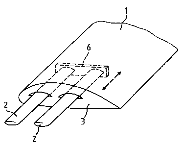
The wing with the span (b) according to the invention has a
main part (1), which has a substantially closed surface with
respect to the flow (v) and is provided at its free end with an
end section in the form of a wing grid. The wing grid has at
least two parallel-staggered winglets (2). Such a wing grid as
part of the wing span (b) takes over the intended profile cir-
culation at the attachment point to the main part and subdiv-
ides said circulation approximately uniformly over the winglets.
Thus, the same lift is produced in the end section with at
least two winglets. Thus, for the wing the circulation distri-
bution is more complete and the induced resistance is decreased.
An upper or lower limit for the action is obtained, as a
function of whether as a result of the fixed wing grid for the
entire wing a rectangular circulation distribution is produced
or only for the part of the overall span replaced by the wing
grid. Thus, for the wing with wing grid there is a correspon-
ding reduction of the induced resistance as compared with a
conventional wing without a wing grid for the same resulting
aspect ratio.


Claims

Note: Claims are shown in the official language in which they were submitted.


-8-
CLAIMS
7. A wing comprising the combination of a main wing part having
a substantially closed surface, a distal end, a chord, a first
predetermined span and a predetermined orientation and
predetermined attack angle relative to incident fluid flow for
producing lift; a tip portion at said distal end of said main
wing part, said tip portion comprising a grid of at least two
spaced-apart winglets having a second predetermined span, said
grid being attached to said distal end of said main wing part and
extending the same lift per span unit of undisturbed two-
dimensional flow around the profile of the main wing at the
attachment to the winglet nips of the grid, each of said winglets
having substantially the same orientation relative to incident
fluid flow as said main wing part, said second predetermined span
being no greater than said first predetermined span, said
winglets having an overlap ratio of winglet chord length to
spacing from an adjacent winglet equal to less than one and a
ratio of chord length to winglet spacing which is substantially
constant along said winglet: span where said spacing is measured
leading edge to leading edge, and said winglets being vertically
staggered relative to each other along a line unidirectionally
angularly separated from a plane containing the chord of the main
wing part.

-9-
2. A wing according to claim 1 wherein said grid comprises four
winglets.
3. A wing according to claim 1 wherein said line along which
said winglets are staggered has an angle above a plane containing
said chord of said main wing part substantially equal to or
greater than a design angle of incidence of said main wing part.
4. A wing according to claim 1 wherein said winglets are twist-
free.
5. A wing according to claim 1 and including means of extending
and retracting said tip portion from and into said main wing
part.
6. A wing according to claim 1 and including a retaining frame
interconnecting distal ends of said winglets.
7. A wing according to claim 1 and including selectable
individual parameters for individual ones of said winglets.
8. A wing according to claim 7 wherein said individual
parameters for individual ones of said winglets include the
length of each winglet chord, a flow angle for said

-10-
winglets including zero incident flow angle, and staggering
distance.
9. A wing according to claim 1 and including means for jointly
varying the angle of fluid flow incidence to said winglets.
10. A wing according to claim 1 wherein said main wing part and
said winglet grid have swept back leading edges, the sweep angles
relative to an incident free stream direction being selected to
allow subsonic operation at high subsonic Mach numbers, thereby
avoiding drag divergence due to compressibility.
11. A wing according to claim 1 wherein said main wing part
comprises a sail for a marine vessel and said tip portion is
positioned at a top of said sail.
12. A wing according to claim 1 wherein said winglets have
leading edges which are parallel with each other.
13. A wing according to claim 1 wherein said line along which
said winglets are staggered is a straight line.
14. A wing according to claim 1 wherein said grid is

-11-
attached to said main wing part with a connecting body
having a flat surface facing said grid.

Description

Note: Descriptions are shown in the official language in which they were submitted.


21~6c~~~
WING WITH A WING GRID AS THE END SECTION
The invention relates to a wing, whose main part has a surface
around which there is a flow. .
According to the invention such a wing 'has at the end of the
main part a wing grid as an end section. At the end of the
main part on a chord t is attached the wing grid, which prod-
uces the same specific lift per length unit of the wing spread
or span as the main part at the fixing point. The wing can e.g.
be the wing of an aircraft or a propeller, or the sail or
centreboard or drop keel of a boat, etc.
The construction of wings is always a compromise between the
strength, which prefers a small aspect :ratio, and the induced
resistance, which requires a large aspect ratio of the wing and
together with the profile resistance determines the lift-drag
(L/D) ratio.
For theoretical reasons it would be desirable to recover part
of the energy given off to the flow medium in the lateral turb-
ulence at the free wing tip and which determines the induced
resistance, or to completely avoid the delivery thereof.
Prior Art.
A recovery with a propeller is known. A partial reduction with
suitably shaped end plates is known. the prior art also dis-
closes various arrangements of individual winglets (e.g. DE-OS
3242584) or several such winglets in series with a negative
setting angle or incidence with respect to the wing chord
(DE-OS 3621800), whose function is to obtain from the wing tip
turbulence useful propulsion and/or life: force by individually
adapted partial deflection.
It is also known to use a split flap-like subdivision of pref-
erably the outer third of the length of a wing for improving

~~~saoa
- 2 -
the efficiency (EP 282 830) by subdividing the boundary layer
running length into laminar portions.
It is also known to subdivide the wing into parallel, grid-like
individual wings with varying length (P'R 7612470, published
under No. 2349494) for a better control. of the wing action.
It is also known to use so-called air waffles, namely a Wing
grid with overlapping winglets, as wings (DE 37 30 798), whose
overall setting angle during flight and whilst maintaining the
setting angle of the winglets is modified for changing the lift
up to an end position in which the winglets are in overlapping
contact.
The replacement of an aircraft wing by an overlapping wing grid
over the entire span is also known (DE 2657714), which also
brings about a rise in efficiency.
It is also known in a device by means of one or more spiral
loops distributed uniformly over the main wing chord to take
over the local profile circulation and deliver it at its outer
end (Aviation Partners, Dr. Louis B. Gratzer, Seattle).
Invention.
The problem to be solved according to the invention is to so
design or supplement the wing tip of a deep, short wing with a
small aspect ratio that as a result lift-drag ratios can be
obtained, which would otherwise only be achieveable with much
more slender wings having a large aspect ratio, or to reduce
the L/D ratios of an existing wing by reducing the induced
resistance.
This problem is solved by the above-described wing with a wing
grid and as defined as an invention in the claims.

2136~~~
- 3 -
According to the invention a partial span of the wing is
replaced by a wing grid formed from at least two parallel, stag-
gered winglets. This wing grid takes over the circulation
around the wing profile fully on that side in which the wing
passes into the fixed wing grid. The upper limit used as a
basis is the circulation around the wing profile without any
wing tip turbulence, which is replaced by the wing tip turbul-
ence of the wing grid. The winglets of: the wing according to
the invention are preferably twist-free and preferably the set-
ting angles thereof are jointly or individually adjustable.
The solution of the problem according to the invention extends
much further than the known solutions, in which by individually
adapted winglets the wing tip turbulence is utilized and avoids
the incomplete use of the effect according to known solutions
with several fixed winglets.
Compared with a closer solution with a regular wing grid and at
least three winglets, according to the preferred embodiment
only at least two winglets are used, but must be staggered in
parallel. The effect of the wing according to the invention
could at best be achieved with a known split flap if the
profiles and setting angles of the split flaps could be adap-
ted over their length to a given degrees of splitting. The nega-
tively acting, maximum grid spacing in known split flap ends
is avoided with the parallel staggering of the winglets accor-
ding to the invention.
The wing grid of the wing according to the invention with its
parallel-staggered, at least two winglets can in the case of
setting angle changes follow up the incident flow v as a whole,
without having to modify the grid parameters and, particularly
when there is no overlapping, can be effective without any
follow-up for a large setting angle range. However, e.g. an
air waffle, which represents the complete bearing surface of

~~3~a~4~
several individual wings, during its adjustment modifies the
multiplane effect and the overlapping winglets lead to a narrow
range of the setting angle usable for an adjustment. As oppo-
sed to the wing according to the invention, with such a waffle
it is not possible to achieve in the case of a wing with a
small aspect ratio a smaller L/D ratio. The known, overlapping
wing grid over the entire span, which i:n fact represents a
multiplane with a small stagger, does not give a multiplane
effect for the induced resistance, but instead a considerable
increase in the profile resistance. The wind split up in grid-
like manner and with a varying length o:E the individual wings
also suffer from this disadvantage, because the individual
wings also extend over the entire span. Compared with a wing
with the known spiral loops for leading off the local profile
circulation, the same effect is exerted by the wing according
to the invention with a planar and therefore less cross-wind-
sensitive and constructionally simpler arrangement.
If the at least two winglets of the wing according to the
invention are connected with the aid of a retaining frame,
there is an approximation to the action of a wing grid formed
from several winglets without a retaining frame and a wing grid
formed from at least three winglets is supplemented and exten-
ded by an effective range.
As only the staggering of the winglets of the wing according to
the invention must be in parallel, wherE~as the other grid para-
meters regarding the circulation distribution to be removed can
be adapted over the chord of the main part, a further optimiz-
ation of the adaptation to the conditions of the main part is
possible.
Embodiments of the wing according to the: invention are descr-
ibed in greater detail hereinafter relative to the drawings,
wherein show:

~_. 21.~G~aO
- 5 -
Fig. 1 The conventional force distribution in lift and
resistance on the incident flow wing profile for
defining the L/D ratio.
Fig. 2 The basic diagram of the wing according to the
invention with a wing grid attached to the conven-
tional main part as the bE~aring section with the
same specific lift per length unit of the span at
the attachment point to the main part.
Fig. 3 An exemplified embodiment of the wing grid with
retaining frame.
Fig. 4 A wing grid, which can be extended from the main
part .
Fig. 5 A use of the wing according to the invention on
the main sail of a yacht.
Fig. 6 A use of the wing according to the invention on an
aircraft.
Fig. 7 A sweepback of the wing grid to the flow direction,
as required by high subsonic speeds.
Fig. 8 The designations of the grid parameters of a
general wing grid in a vertical sectional
representation.
Fig. 1 shows the incident flow v of a wing profile with finite
span or wingspread, a lift A and a resistance W being obtained.
The ratio of these forces gives the L/D ratio according to the
f ormu la
L/D ratio = tg( pC) - W/A
in which W = W1 + Wr = induced resistance + frictional
resistance.

~~~saao
- 6 -
The wing according to the invention reduces the part WI of the
induced resistance caused by the flow round the wing tips.
Fig. 2 shows a wing with a main part l, which begins at the
symmetry plane in the centre. To the main part 1 is attached a
portion of the total bearing wing span b with a wing grid com-
prising winglets 2 of similar orientation and parallel stagg-
ering. The winglets 2 are placed over the chord t.
The desired action for the design point. is obtained if the
circulation in the profile sections S a.nd S' is of the same
size and similar rotation axis and if the winglets form a wing
grid, which zonally takes over the circulation along the chord
of the main part. The attachment point of the wing grid is, as
stated, constructed as a partition 3.
Fig. 3 shows an exemplified embodiment of the wing according to
the invention, in which the outer ends of the winglets 2 are
held in a retaining frame 4, which has the function of a clos-
ing face for the flow distribution.
Fig. 4 is an exemplified embodiment of the wing according to
the invention with an extendable wing grid, whose winglets are
fixed to a plate 6 and are moved as an entire group. Embodi-
ments are also conceivable with individually extendable wing-
lets.
Fig. 5 shows as a use of the wing according to the invention a
yacht 8 with a mast 7 and a mainsail 1, whose upper edge is
provided with a wing grid (2, 4).
Fig. 6 shows an exemplified embodiment of the wing according to
the invention with a wing grid constituted by winglets 2, part-
ition 3 and retaining frame 4, the winglets being extendable as
a group with the plate 6 from the main part 1 of a triangular
aircraf t wing .

,r.~ 2~3fi0fl~
_, _
Fig. 7 shows the use of a swept back wing grid, such as is e.g.
used for high subsonic speeds. As a function of the design of
the winglets 2, as a function of the setting angle and profile
thickness of the winglets, the resulting sweepback designed for
the same Mach number differs from the sweepback of the main
wing part 1.
Fig. 8 shows the designations of the grid parameters of a wing
grid for a wing according to the invention. The staggering
direction 0 of the wing grid to the incident flow direction v
can be chosen at random and what is decisive for the action is
the setting angle j3, based on the chords, as shown in the
drawing, and more specifically the zero incident flow angle of
the winglets, the length of the chords c and the staggering s
transversely to the incident flow direction v. The quantity g
is the grid spacing in the staggering direction 0.

Representative Drawing
A single figure which represents the drawing illustrating the invention.
Administrative Status

2024-08-01:As part of the Next Generation Patents (NGP) transition, the Canadian Patents Database (CPD) now contains a more detailed Event History, which replicates the Event Log of our new back-office solution.

Please note that "Inactive:" events refers to events no longer in use in our new back-office solution.

For a clearer understanding of the status of the application/patent presented on this page, the site Disclaimer , as well as the definitions for Patent , Event History , Maintenance Fee  and Payment History  should be consulted.

Event History

Description Date
Time Limit for Reversal Expired 2004-03-30
Letter Sent 2003-03-31
Grant by Issuance 2001-10-30
Inactive: Cover page published 2001-10-29
Inactive: Final fee received 2001-07-12
Pre-grant 2001-07-12
Notice of Allowance is Issued 2001-01-26
Letter Sent 2001-01-26
Notice of Allowance is Issued 2001-01-26
Inactive: Approved for allowance (AFA) 2001-01-05
Amendment Received - Voluntary Amendment 2000-12-08
Inactive: S.30(2) Rules - Examiner requisition 2000-06-28
Amendment Received - Voluntary Amendment 1999-02-02
Inactive: Application prosecuted on TS as of Log entry date 1997-10-24
Inactive: RFE acknowledged - Prior art enquiry 1997-10-24
Inactive: Status info is complete as of Log entry date 1997-10-24
All Requirements for Examination Determined Compliant 1997-10-06
Request for Examination Requirements Determined Compliant 1997-10-06
Application Published (Open to Public Inspection) 1994-10-13

Abandonment History

There is no abandonment history.

Maintenance Fee

The last payment was received on 2001-03-19

Note : If the full payment has not been received on or before the date indicated, a further fee may be required which may be one of the following

  • the reinstatement fee;
  • the late payment fee; or
  • additional fee to reverse deemed expiry.

Patent fees are adjusted on the 1st of January every year. The amounts above are the current amounts if received by December 31 of the current year.
Please refer to the CIPO Patent Fees web page to see all current fee amounts.

Fee History

Fee Type Anniversary Year Due Date Paid Date
Request for examination - small 1997-10-06
MF (application, 4th anniv.) - small 04 1998-03-30 1998-03-04
MF (application, 5th anniv.) - small 05 1999-03-30 1999-03-04
MF (application, 6th anniv.) - small 06 2000-03-30 2000-03-21
MF (application, 7th anniv.) - small 07 2001-03-30 2001-03-19
Final fee - small 2001-07-12
MF (patent, 8th anniv.) - small 2002-04-02 2002-03-22
Owners on Record

Note: Records showing the ownership history in alphabetical order.

Current Owners on Record
ULRICH LA ROCHE
Past Owners on Record
None
Past Owners that do not appear in the "Owners on Record" listing will appear in other documentation within the application.
Documents

To view selected files, please enter reCAPTCHA code :


To view images, click a link in the Document Description column. To download the documents, select one or more checkboxes in the first column and then click the "Download Selected in PDF format (Zip Archive)" or the "Download Selected as Single PDF" button.

List of published and non-published patent-specific documents on the CPD .

If you have any difficulty accessing content, you can call the Client Service Centre at 1-866-997-1936 or send them an e-mail at CIPO Client Service Centre.


Document
Description 
Date
(yyyy-mm-dd) 
Number of pages   Size of Image (KB) 
Claims 1995-10-21 2 130
Claims 2000-12-07 4 96
Abstract 1995-10-21 1 29
Description 1995-10-21 7 261
Drawings 1995-10-21 4 53
Claims 1999-02-01 4 91
Representative drawing 2001-10-02 1 5
Abstract 2001-08-26 1 29
Representative drawing 1999-05-19 1 18
Acknowledgement of Request for Examination 1997-10-23 1 173
Commissioner's Notice - Application Found Allowable 2001-01-25 1 164
Maintenance Fee Notice 2003-04-27 1 174
Correspondence 2001-07-11 1 38
Fees 1999-03-03 1 30
Fees 2000-03-20 1 30
Fees 2002-03-21 1 31
Fees 2001-03-18 1 30
PCT 1994-11-15 9 284
Fees 1998-03-03 1 38
Fees 1997-03-04 1 31
Fees 1996-03-12 1 31