Language selection

Search

Patent 2136005 Summary

Third-party information liability

Some of the information on this Web page has been provided by external sources. The Government of Canada is not responsible for the accuracy, reliability or currency of the information supplied by external sources. Users wishing to rely upon this information should consult directly with the source of the information. Content provided by external sources is not subject to official languages, privacy and accessibility requirements.

Claims and Abstract availability

Any discrepancies in the text and image of the Claims and Abstract are due to differing posting times. Text of the Claims and Abstract are posted:

  • At the time the application is open to public inspection;
  • At the time of issue of the patent (grant).
(12) Patent: (11) CA 2136005
(54) English Title: ELECTROMAGNETIC DOOR LOCK ARMATURE ASSEMBLY
(54) French Title: ARMATURE DE SERRURE DE PORTE ELECTROMAGNETIQUE
Status: Expired and beyond the Period of Reversal
Bibliographic Data
(51) International Patent Classification (IPC):
  • E05C 19/16 (2006.01)
(72) Inventors :
  • WALTZ, KEVIN P. (United States of America)
(73) Owners :
  • VON DUPRIN, INC.
(71) Applicants :
  • VON DUPRIN, INC. (United States of America)
(74) Agent: NORTON ROSE FULBRIGHT CANADA LLP/S.E.N.C.R.L., S.R.L.
(74) Associate agent:
(45) Issued: 2002-06-04
(86) PCT Filing Date: 1992-10-27
(87) Open to Public Inspection: 1994-02-17
Examination requested: 1999-09-08
Availability of licence: N/A
Dedicated to the Public: N/A
(25) Language of filing: English

Patent Cooperation Treaty (PCT): Yes
(86) PCT Filing Number: PCT/US1992/009361
(87) International Publication Number: US1992009361
(85) National Entry: 1994-11-16

(30) Application Priority Data:
Application No. Country/Territory Date
921,777 (United States of America) 1992-07-30

Abstracts

English Abstract


An electromagnetic door lock assembly employs an electromagnet (10) positioned
in a frame adjacent to a door, and an ad-
justable armature assembly positioned in the door for interaction with the
electromagnet. The armature assembly (24) includes an
armature plate (28) having a pair of shear low-cost, replaceable elements that
initially engage the electromagnet (10). A backing
plate (46) is situated adjacent to the armature plate, and a stem coupling the
backing plate to the armature plate includes a spring
biasing the backing plate (46) and armature plate (28) toward each other. A
mounting portion for mounting the armature assem-
bly (24) to a door to be locked is provided with adjusting screws for
adjustably positioning the backing plate at a fixed position
with respect to the mounting portion so that the armature plate (28) is
positioned at a first position for optimum interaction with
the electromagnet (10), the screws having elongated heads for maintaining the
relative alignment between the armature plate (28)
and the mounting portion as the armature plate moves between the first
position and a position contiguous to the electromagnet
(10).


Claims

Note: Claims are shown in the official language in which they were submitted.

What is claimed is:
1. An electromagnetic door lock assembly of the type having an electromagnet
(10) including a mounting means (14) for mounting said electromagnet (10) in a
frame
adjacent to a door and an armature means (24) provided for positioning in the
door for
interaction with the electromagnet (10), the armature means (24) including an
armature
plate (28), a backing plate (46) and a biasing means (56) for biasing the
armature plate
(28) away from the electromagnet (10) wherein the improvement comprises:
said mounting means including a shoulder means (22) for interacting with said
associated armature means (24) to enhance resistance to shearing movement
between
the electromagnet and said armature;
first and second shear elements (24 and 36) replaceably affixed to the
armature
plate (28) to confront said shoulder means (22), said shear elements (34, 36)
being
composed of a material which will result in differential wear occurring upon
the shear
elements (34, 36) rather than said shoulder means (22).
2. ~The door lock assembly of claim 1, wherein said shear elements are
composed
of a material having a hardness less than the hardness of said shoulder means.
3. ~The door lock assembly of either of claims 1 or 2, wherein the removable
shear elements are composed of a sintered, powdered stainless steel.
4. ~The door lock assembly of any of claims 1, 2 or 3, wherein said first and
second shear elements are attached at opposite ends of the armature plate by a
plurality
of threaded screws.
5. ~The door lock assembly of claim 4, wherein the first and second shear
elements
are formed to include channel means for enveloping said shoulder means
extending
toward the armature. plate from the electromagnet to inhibit relative lateral
movement
of the armature means and electromagnet when the electromagnet is energized.

7
6. The door lock assembly of claim 1, wherein the armature means further
comprises coupling means for coupling the backing plate to the armature plate,
said
biasing means biasing the backing plate and armature plate toward each other.
7. The door lock assembly of claim 6, wherein the coupling means comprises a
first element fixed to the armature plate for movement therewith, the backing
plate
being movable with respect to the first element and said biasing means acting
between
the first element and the backing plate to bias the backing plate and armature
plate
toward each other.
8. The door lock assembly of claim 1, wherein the armature means further
comprises a mounting portion for mounting the armature means to said door to
be
locked, adjusting means for adjustably positioning the backing plate at a
fixed position
with respect to the mounting portion so that a front surface of the armature
plate is
positioned at a first position for optimum interaction with the electromagnet,
and
alignment means for maintaining the relative alignment between the armature
plate and
the mounting portion as the armature plate moves between said first position
and a
position contacting the electromagnet.
9. The door lock assembly of claim 8, wherein the adjusting means comprises
threaded elements engaging the backing plate and rotatable with respect to the
mounting portion for adjusting the displacement of the backing plate with
respect to
the mounting portion.
10. The door lock assembly of claim 8, wherein the armature means further
comprises spacer means for spacing the armature plate from the backing place
by a
selected minimum distance to prevent contact between the armature plate and
backing
plate upon return of the armature plate to the first position.

Description

Note: Descriptions are shown in the official language in which they were submitted.


n~ r
~1~~~~~~:~
DOOR LOCK ARMATURE ASSEMBLY
BAC1~~ROUND OF THE INVENTION
The present invention relates generally to electromagnetic door locking
devices
and more particularly to shear locks having improved features which ensure
that the
lock operates rapidly and positively during both locking and unlocking
operations.
Various types of electromagnetic door locks are known. One type commonly
referred to as a shear lock comprises an electromagnet mounted to or in a
frame
defining a doorway. One such device is disclosed in U.S. Patent 4,981,312. An
armature is movably mounted to travel with a door as the door moves in the
doorway
between an "open" and "closed" position. When the door is in the closed
position, the
armature is positioned in spaced relation from the electromagnet, but is
mounted to or
in the door such that when power is applied to the electromagnet the armature
responds to the magnetic field and becomes engaged on an adjacent surface of
the
electromagnet.
Various styles and types of shoulder means such as ledges, tangs, and tabs
have
been employed to provide some physical interrelationship between the face of
the
electromagnet and the armature to enhance the lock's resistance to a shearing
movement which would result from any attempt to open the door while power was
applied to the electromagnet. An example of a device employing this feature is
U.S.
Patent 5,006,723. It has been observed that such shoulder means exhibit
increasing
wear and potentially decreasing performance with time, thus mandating
replacement of
the shoulder elements exhibiting such wear. Where the shoulder elements are
integral
with the major elements of the electromagnetic lock, such replacement can be
quite
costly. .
It would therefore be desirable to provide such shoulder means in the form of
easily replaced, separate, low cost elements. Preferably, such replaceable
elements are
constructed to have material hardness less than the material hardness of the
elements
with which they cooperate to achieve the desired physical shear-inhibiting
interrelationship. This selection of lesser material hardness results in
reduced wear on
" fhe cooperating element thereby extending the life of the lock as a whole.
AMENDED SHEET
IPEAIEP

2~~~~ ?~ ,;:
WO 94103691 PCT/US92/09361
1
2
The foregoing illustrates limitations known to exist in present devices and
methods. Thus, it is apparent that it would be advantageous to provide an
alternative
directed to overcoming one or more of the limitations set forth above.
Accordingly, a
suitable alternative is provided including features more fully disclosed
hereinafter.
~tJMMARY OF THE 1NVENTI~N
In one aspect of the present invention, this is accomplished by providing an
electromagnetic door lock assembly which can be used in combination with an
electromagnet mounted in a frame adjacent a door such that a shoulder
interacts with
an associated armature assembly to enhance resistance to shearing movement
between
the electromagnet and the armature assembly. The armature assembly is provided
for
positioning in the door for interaction with the electromagnet. The armature
assembly
includes an armature plate and a. backing plate. The armature plate is biased
away
- from the electromagnet. First and second shear elements are replaceably
affixed to the
armature plate to confront the shoulder.
The foregoing and other aspects will become apparent from the following
detailed description of the invention when considered in conjunction with the
accompanying drawing figures. .
BRIEF DES RIPTION OF THA nR_AW1NGS
Figure 1 is a side elevation of a typical electromagnet employed in a door
lock
assembly according to the present invention;
Figure 2 is a plan view of an armature assembly designed for interaction with
the electromagnet of Figure I; and
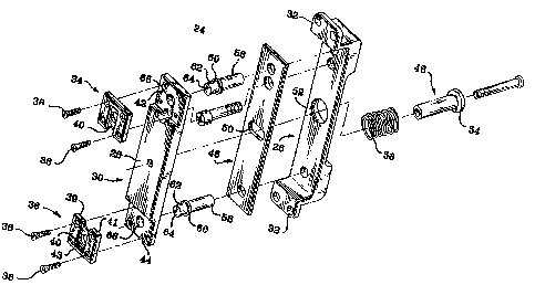
Figure 3 is an exploded perspective view of the armature assembly shown in
Figure 2.

1~ '
W~19410369I PCT/US92/09361
3
DETAILED DESCRIPTIO_N_
An electromagnet 10 for use with an armature in a door lock in accordance
with the present invention is shown .in Figure 1. The electromagnet 10
comprises a
coil potted in a housing 12. The housing 12 includes mounting portions 14 at
each
end of the coil which are adapted to be secured to a door frame by screws or
other
similar fastening means passing through openings 16. The electromagnet
includes a
lower face 18 adapted to be confronted by a cooperating armature such as is
shown in
Figure 2. The lower face 18 of the electromagnet 10 is contacted by the
armature
plate when power is applied to the coil through wire 20 from a power source,
not
shown. Shoulder means in the form of projections 22 are provided on the
mounting
portions 14 to interact with cooperating structure on the armature to enhance
the lock's
resistance to any applied shearing force.
An armature assembly 24 is shown in Figure 2 to comprise a mounting portion
-. _--_.-.---. -...--_26 which receives an armature plate 28 having an upper
surface 30 confronting and.
intended to contact surface 18 of the electromagnet 10. The mounting portion
26 is
adapted to be secured to a door by screws or other similar fastening means
passing
through openings 32. The armature plate 28 is adapted to receive replaceable
shear
elements 34 and 36 which are affixed an the ends of the armature piate 28 by
screws
38 or other similar fastening means to the .mounting portions 14 of the
electromagnet
housing 12. The shear elements 34 and 36 are formed to include a central
groove 40
adapted to receive the projection 22 from the confronting electromagnet
mounting
portion 14. The central groove 40 is defined by side ledge portions 39 and 41,
and by
end ledge portion 43. The end ledge portion 43 of both shear elements 34 and
36 are
preferably dimensioned to physically contact at least one of the ends of
projections 22
prior to and effectively preventing any contact between projections 22 and the
armature plate 28.
The armature assembly 24 is shown in more detail in Figure 3 to include steps
or recesses 42 and 44 at opposite ends of the armature plate 28 for receiving
the shear
elements 34 and 36 respectively. The shear elements 34 and 36 are connected to
the

G
WO 94/03691 PCT/US92/09361 :--
4
armature plate 28 by threaded screws 38. When necessary, due to wear or
damage, the
;;
threaded screws 38 can be temporarily removed, and the shear elements 34
replaced.
This operation is relatively simple, and can be accomplished without further
disassembly of the armature assembly 24 or removal of the door to which the
armature
assembly is mounted.
The armature plate 28 is coupled to a separate backing plate 46 by a stud or .
similar element 48 which is secured to the armature plate 28. The stud 48
projects
through an opening 50 in backing plate 46 and through another opening ~2 in
mounting portion 26. The stud 48 includes an outwardly projecting flange 64 at
a rear
most end of the stud. A coil spring 56 surrounds the stud with one end of the
spring
contacting the flange 54 and the other end of the spring contacting a back
surface of
the backing plate 46. The spring 56 acts as .a biasing means for biasing the
flange 54
i
away from backing plate 46 which has the effect of biasing the backing plate
46 and
armature plate 28 toward each other. In the presence of a magnetic field
generated by
the electromagnet 20; the armature plate 28 moves with respect to_ the backing
, plate 46
against the . biasing force applied by the spring 56. I v'
A pair of threaded suds 58 are provided which are adjustably engaged with the
mounting portion 26. Each of the studs 58 includes an integral radial flange
60. Any
outward adjustment of the studs ~8 with respect to the mounting portion 26
causes the
flanges 60 to move outward thereby ,displacing the armature plate 28 away from
the
mounting portion 26 and toward the electromagnet 10. Any outward adjustment of
the
rest position of the armature plate 28 by adjustment of the threaded studs ~8
also
causes the backing plate 46 to move outward since the backing plate 46 and
armature
plate 28 are biased toward each other by spring 56 as previously described. It
will be
noted that the biasing force against which the electromagnet 10 must act to
attract the
armature plate 28 is set by the spring constant of spring ~6. The biasing
force is
independent of the adjustment of threaded studs which merely sets the original
distance
of separation between the electromagnet 10 and armature plate 28.
The movement of the armature plate 28 in response to an applied magnetic
field is guided by means of openings 66 which surround the upper portion 62 of
the

u'~ 94/03691 PCT/US92/09361
threaded studs 58. The upper ends 64 of the studs 58 project through openings
66 in
the shear elements 34 and 36, and are substantially coplanar with the surface
40 of the
shear elements 34 in the absence of an applied magnetic field. Thus, the
guiding
function provided by the interaction. between the openings 66 and the upper
portions
62 operates aver a range of movement 'about equal to the thickness of the
armature
plate 28.
Preferably, the shear elements 34 and 36 are fabricated from a material which
is different from mounting portions 14 for the electromagnet 10. While the
shear
elements 34 and 36 could be constructed as integral stainless steel pieces,
the preferred
composition is sintered, powdered stainless steel. The shear elements 34 and
36 are
preferably formed to have a hardness slightly less than the hardness of the
projections
22 on the electromagnet mounting portion 14. The material forming the shear
elements can also include self lubricating characteristics and surface
smoothness
characteristics designed to maximize the service Iife of the inserts. This
construction
ensures that~any-contact betweenwthe shear elements and the shoulder means 22
will
result in differential wear upon the shear elements, which can be economically
and
easily replaced at the site. Because of their attachment by threaded screws,
the shear
elements are more readily replaceable than either the electromagnet mounting
portion
or an entire unitary armature plate of the type typically used in the prior
art. The use
of an armature assembly as described and shown reduces maintenance costs and
increases the useful service life of any electromagnetic lock system in which
they are
employed.
Although the invention has been described in detail with reference to the
illustrated preferred embodiments, variations and modifications exist within
the scope
and spirit of the invention as described and as defined in the following
claims.
J
., 1

Representative Drawing
A single figure which represents the drawing illustrating the invention.
Administrative Status

2024-08-01:As part of the Next Generation Patents (NGP) transition, the Canadian Patents Database (CPD) now contains a more detailed Event History, which replicates the Event Log of our new back-office solution.

Please note that "Inactive:" events refers to events no longer in use in our new back-office solution.

For a clearer understanding of the status of the application/patent presented on this page, the site Disclaimer , as well as the definitions for Patent , Event History , Maintenance Fee  and Payment History  should be consulted.

Event History

Description Date
Time Limit for Reversal Expired 2004-10-27
Letter Sent 2003-10-27
Grant by Issuance 2002-06-04
Inactive: Cover page published 2002-06-03
Inactive: Final fee received 2002-03-20
Pre-grant 2002-03-20
Notice of Allowance is Issued 2002-01-09
Letter Sent 2002-01-09
Inactive: Approved for allowance (AFA) 2001-12-19
Amendment Received - Voluntary Amendment 1999-12-02
Letter Sent 1999-10-05
Inactive: Application prosecuted on TS as of Log entry date 1999-10-04
Inactive: Status info is complete as of Log entry date 1999-10-04
Request for Examination Requirements Determined Compliant 1999-09-08
All Requirements for Examination Determined Compliant 1999-09-08
Application Published (Open to Public Inspection) 1994-02-17

Abandonment History

There is no abandonment history.

Maintenance Fee

The last payment was received on 2001-10-05

Note : If the full payment has not been received on or before the date indicated, a further fee may be required which may be one of the following

  • the reinstatement fee;
  • the late payment fee; or
  • additional fee to reverse deemed expiry.

Patent fees are adjusted on the 1st of January every year. The amounts above are the current amounts if received by December 31 of the current year.
Please refer to the CIPO Patent Fees web page to see all current fee amounts.

Fee History

Fee Type Anniversary Year Due Date Paid Date
MF (application, 5th anniv.) - standard 05 1997-10-27 1997-10-08
MF (application, 6th anniv.) - standard 06 1998-10-27 1998-10-14
Request for examination - standard 1999-09-08
MF (application, 7th anniv.) - standard 07 1999-10-27 1999-10-15
MF (application, 8th anniv.) - standard 08 2000-10-27 2000-10-13
MF (application, 9th anniv.) - standard 09 2001-10-29 2001-10-05
Final fee - standard 2002-03-20
MF (patent, 10th anniv.) - standard 2002-10-28 2002-10-03
Owners on Record

Note: Records showing the ownership history in alphabetical order.

Current Owners on Record
VON DUPRIN, INC.
Past Owners on Record
KEVIN P. WALTZ
Past Owners that do not appear in the "Owners on Record" listing will appear in other documentation within the application.
Documents

To view selected files, please enter reCAPTCHA code :


To view images, click a link in the Document Description column (Temporarily unavailable). To download the documents, select one or more checkboxes in the first column and then click the "Download Selected in PDF format (Zip Archive)" or the "Download Selected as Single PDF" button.

List of published and non-published patent-specific documents on the CPD .

If you have any difficulty accessing content, you can call the Client Service Centre at 1-866-997-1936 or send them an e-mail at CIPO Client Service Centre.

({010=All Documents, 020=As Filed, 030=As Open to Public Inspection, 040=At Issuance, 050=Examination, 060=Incoming Correspondence, 070=Miscellaneous, 080=Outgoing Correspondence, 090=Payment})


Document
Description 
Date
(yyyy-mm-dd) 
Number of pages   Size of Image (KB) 
Claims 1999-10-18 2 86
Abstract 1995-11-10 1 65
Claims 1995-11-10 2 102
Description 1995-11-10 5 281
Drawings 1995-11-10 2 66
Representative drawing 2001-12-19 1 21
Representative drawing 1999-08-09 1 12
Reminder - Request for Examination 1999-06-28 1 118
Acknowledgement of Request for Examination 1999-10-04 1 193
Commissioner's Notice - Application Found Allowable 2002-01-08 1 164
Maintenance Fee Notice 2003-12-21 1 174
Correspondence 2002-03-19 2 48
PCT 1994-11-15 15 587
Fees 1996-09-19 1 57
Fees 1995-09-28 1 50
Fees 1994-11-15 1 48